
Related Manuals for Sole Fitness F60 16810360


Summary of Contents for Sole Fitness F60 16810360
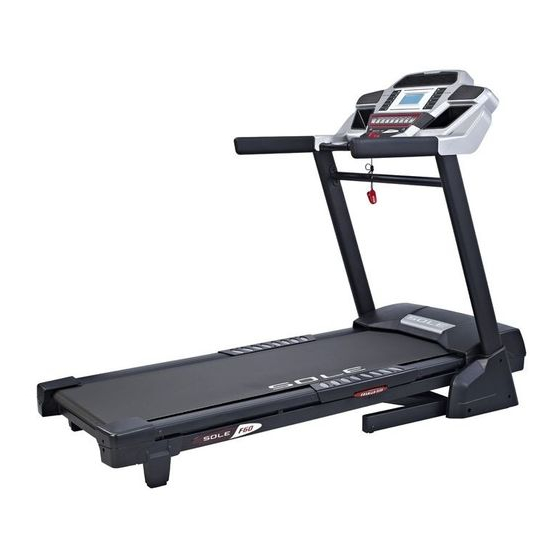
- Page 1 Model:16810360 OWNER’S MANUAL PLEASE CAREFULLY READ THIS ENTIRE MANUAL BEFORE OPERATING YOUR NEW TREADMILL!
-
Page 2: Table Of Contents
TABLE OF CONTENTS Product Registration.....………………..……………………………………1 Important Safety Instructions……………..………………………………………2 Important Electrical Information………..………………………... ………………3 Important Operation Instructions...……………………………………………….4 Important Safety Instructions................5 Assembly Pack Checklist……………………….………….………………………6 Assembly Instructions………………………………………………………………8 Folding Instructions…………………………………………………………………11 Transport Instructions………………………………………………………………11 Operation of Your Treadmill…………………………………………………..……12 Programmable Features……………………………………………………………16 General Maintenance…………………………………………………………..…...23 Service Checklist-Diagnosis Guide…………………………………………..……26 Exploded View Diagram…………………………………………... ……………….28 Parts List….………………………………..……………………..…………………..29 Manufacturer’s Limited Warranty………………………………………………...…33... -
Page 3: Product Registration
CONGRATULATIONS ON YOUR NEW TREADMILL AND WELCOME TO THE SOLE FAMILY! Thank you for your purchase of this quality treadmill from Dyaco Canada Inc. Your new treadmill has been manufactured by one of the leading fitness manufacturers in the worod and is backed by one of the most comprehensive warranties available. -
Page 4: Important Safety Instructions
IMPORTANT SAFETY INSTRUCTIONS WARNING - Read all instructions before using this appliance. DANGER - T o reduce the risk of electric shock disconnect your treadmill from the electrical outlet prior to cleaning and/or service work. WARNING - T o reduce the risk of burns, fire, electric shock, or injury to persons, install the treadmill on a flat level surface with access to a 110-volt, 15-amp grounded outlet with only the treadmill plugged into the circuit. -
Page 5: Important Electrical Information
IMPORTANT ELECTRICAL INFORMATION WARNING! NEVER use a ground fault circuit interrupt (GFCI) wall outlet with this treadmill. As with any appliance with a large motor, the GFCI will trip often. Route the power cord away from any moving part of the treadmill including the elevation mechanism and transport wheels. NEVER remove any cover without first disconnecting AC power. -
Page 6: Important Operation Instructions
IMPORTANT OPERATION INSTRUCTIONS NEVER operate this treadmill without reading and completely understanding the results of any operational change you request from the computer. Understand that changes in speed and incline do not occur immediately. Set your desired work level on the computer console and release the adjustment key. The computer will obey the command gradually. -
Page 7: Important Safety Instructions
IMPORTANT SAFETY INSTRUCTIONS READ BEFORE UNPACKING YOUR FOLDING TREADMILL Serious injury could occur if this folding treadmill is not unpacked properly. There is a Velcro strap installed around the treadmill base that prevents the treadmill from unfolding accidentally during shipping. If this strap is not removed properly the treadmill could spring open unexpectedly and cause injury if someone is standing near the treadmill when the strap is removed. -
Page 8: Assembly Pack Checklist
F60 ASSEMBLY PACK CHECKLIST HARDWARE STEP 2 #76. Ø5/16" × Ø18 × 1.5T #97. 5/16" × 1/2" Flat Washer (8 pcs) Hex Head Bolt (8pcs) HARDWARE STEP 3 #95. M5 × 15m/m Phillips Head Screw (6 pcs) HARDWARE STEP 5 #93. - Page 9 ASSEMBLY TOOLS #99. M6(68 × 88) #98. Combination M5(25 × 90m/m) Allen Wrench (1pc) Allen Wrench & Phillips Head Screw Driver (1pc) #100. 13m/m Wrench (1pc) Dyaco Canada Inc .2013...
-
Page 10: Assembly Instructions
F60 ASSEMBLY INSTRUCTIONS ASSEMBLY STEP 1 Remove the treadmill from the carton and position it aside on a smooth, level floor.The rear should be at least 3’from any wall.Do not remove the Velcro belt until you have rmoved the plastic wrap and styrofoam from beneath the unit. - Page 11 ASSEMBLY STEP 3 HARDWARE STEP 3 #95. M5 × 15m/m Phillips Head Screw (6 pcs) Install Frame Base Cover (L-33&R-34),on the Frame Base(2) and secure with six Phillips Head Screws (95)by using Combination M5 Allen Wrench & Phillips Head Screw Driver (98) ASSEMBLY STEP 4 To complete this step,it is recommended that you find something to rest the Console on at the appropriate height or have someone hole the console while...
- Page 12 ASSEMBLY STEP 5 HARDWARE STEP 5 #93. Ø10 Split Washer (4 pcs) #94. 3/8" × 1-1/2" Button Head Socket Bolts (4pcs) ASSEMBLY STEP 1 Insert the Console Assembly ( 19 ) into the Upright Tubes (R- 4& L -5 )and attach with four Button Head Socket Bolts ( 94 ) with four Split Washers ( 93 ).by using M6 Allen Wrench( 99 ).
-
Page 13: Folding Instructions
ASSEMBLY STEP 7 19-4 19-3 Put Left and right Drink Bottle Holders(19-3) and (19-4) in their places on The Console Assembly(19).Press in until they snap in place. FOLDING INSTRUCTIONS Do not attempt to move the unit unless it is in the folded and locked position. Be sure the power cord is secured to avoid possible damage. -
Page 14: Operation Of Your Treadmill
OPERATION OF YOUR TREADMILL Getting familiar with the control panel Console ■ GETTING STARTED CONSOLE : Power the treadmill on by plugging it into an appropriate wall outlet, then turn on the power switch located at the front of the treadmill below the motor hood. Ensure that the Safety Key is installed, as the treadmill will not power on without it. -
Page 15: Incline Feature
QUICK-START OPERATION 1. Attach the Safety Key to wake the display up (if not already on). 2. Press the Start key to begin belt movement then adjust to the desired speed using the Speed keys on the console. You may also use the Quick speed keys 1, 2, 4, 6, 8, or 10 to adjust the speed. 3. -
Page 16: Calorie Display
DOT MATRIX CENTER DISPLAY Twenty columns of dots (8 high) indicate each segment of a workout. The dots are only to show an approximate level (speed/incline) of effort. They do not necessarily indicate a specific value - only an approximate percent to compare levels of intensity. In operation, the speed/incline dot matrix window will build a profile “picture”... - Page 17 PULSE FEATURE The Pulse (Heart Rate) Window will display your current heart rate in beats per minute during the workout. You must use both stainless steel sensors on the front cross bar to display your pulse or wear the wireless chest strap.
-
Page 18: Programmable Features
PROGRAMMABLE FEATURES The F60 has ten built-in programs: one Manual program, five preset profiles, two user defined programs (U1 & U2) and two Heart Rate programs (HR1 & HR2). Hill The Hill program simulates going up and down a hill. The workload will steadily increase and then decrease during the program. -
Page 19: Selecting A Program
SELECTING A PROGRAM 1. Press the Speed keys to view the programs on the screen then press the Enter key to select the program you would like to perform. The display will prompt you through the programming steps or you can just press the Start key to begin the program using the preset program values for age, weight and other program specific information. -
Page 20: User Programs
USER PROGRAMS Select User 1 or User 2 via the Speed keys then press Enter. Note that the dot matrix display portion will have a single row of dots at the bottom (Unless there is a previously stored program). If there is a program stored under the button that is pressed, it will be retrieved. -
Page 21: Heart Rate Programs
Heart Rate programs Before we get started, a word about Heart Rate: The old motto, “no pain, no gain”, is a myth that has been overpowered by the benefits of exercising comfortably. A great deal of this success has been promoted by the use of heart rate monitors. With the proper use of a heart rate monitor, many people find that their usual choice of exercise intensity was either too high or too low and exercise is much more enjoyable by maintaining their heart rate in the desired benefit range. - Page 22 RATE OF PERCEIVED EXERTION Heart rate is important but listening to your body also has a lot of advantages. There are more variables involved in how hard you should workout than just heart rate. Your stress level, physical health, emotional health, temperature, humidity, the time of day, the last time you ate and what you ate, all contribute to the intensity at which you should workout.
- Page 23 USING HEART RATE TRANSMITTER (Optional) How to wear your wireless chest strap transmitter: Attach the transmitter to the elastic strap using the locking parts. Adjust the strap as tightly as possible as long as the strap is not too tight to remain comfortable. Position the transmitter with the logo centered in the middle of your body facing away from your chest (some people must position the transmitter slightly left of center).
- Page 24 HEART RATE CONTROL PROGRAMMING CAUTION! Heart Rate Control programs are intended for wireless transmitter chest strap. Do not use Pulse Grip bar for Heart Control. You must receive a strong/steady value in the heart rate window (See Using Heart Rate Transmitter section for instrucions on how to use). The HR1 program has a default level that is 60% of your projected heart rate maximum.
-
Page 25: General Maintenance
GENERAL MAINTENANCE BELT & DECK Your treadmill uses a very high-efficient low-friction deck. Performance is maximized when the deck is kept as clean as possible. Use a soft,damp cloth,or paper towel,wipe the edge of the belt and the area between the belt edge and the frame. Also reach as far as practical directly under the belt edge. - Page 26 TREAD-BELT TRACKING ADJUSTMENT The treadmill is designed so that the tread-belt remains reasonably centered while in use. It is normal for some belts to drift near one side while in use, depending on a user’s gait and if they favor one leg. But if during use the belt continues to move toward one side, adjustments arenecessary. TO SET TREAD-BELT TRACKING A 6 mm Allen wrench (99)is provided for this adjustment.
- Page 27 BELT/DECK LUBRICATION Keeping the deck lubricated at the recommended intervals ensures the longest life possible for your treadmill. If the lubricant dries out, the friction between the belt and deck rises and places undue stress on the drive motor, drive belt and electronic motor control board, which could result in catastrophic failure of these expensive components.
-
Page 28: Service Checklist-Diagnosis Guide
SERVICE CHECKLIST – DIAGNOSIS GUIDE Before contacting your dealer for aid, please review the following information. It may save you both time and expense. This list includes common problems that may not be covered under the treadmill’s warranty. ROBLEM SOLUTION/CAUSE Display does not light 1.Tether cord not in position. -
Page 29: Calibration Procedure
CALIBRATION PROCEDURE 1. Remove the Safety Key. 2. Press and hold down the Start and Speed buttons and replace the Safety Key. Continue to hold the Start and Speed key until the window displays “Factory settings”, then press the Enter key. 3. -
Page 30: Exploded View Diagram
EXPLODED VIEW DIAGRAM -28- Dyaco Canada Inc .2013... -
Page 31: Parts List
PARTS LIST KEY NO. PART NO. DESCRIPTION Q’TY 1036001 Main Frame 1036002 Frame Base 1036003 Incline Bracket 1036004 Right Upright 1036005 Left Upright 1036006 Console Support 1036007 Outer Slide 1036008 Inner Slide 1036009 Handrail Support 1036010 Foot Pad Plate 1036011 Drive Belt 1036012 Front Roller W/Pulley... - Page 32 KEY NO. PART NO. DESCRIPTION Q’TY 1036022 Top Motor Cover Plate 1036023 Rubber Foot 1036024 Belt Guide 1036025 Motor Cover Anchor 1036026 Rear Adjustment Base (L) 1036027 Rear Adjustment Base (R) 1036028 Rear Foot Cover (L) 1036029 Rear Foot Cover (R) 1036030 Motor Bracket 1036031...
- Page 33 KEY NO. PART NO. DESCRIPTION Q’TY 1036069 M6 × 25m/m_Flat Head Countersink Bolt 1036070 M8 × 12m/m_Hex Head Bolt 1036071 3/8"_Nyloc Nut 1036072 5/16"_Nyloc Nut 1036073 M8_Nyloc Nut 1036074 Ø25 × Ø10 × 2.0T_Flat Washer 1036075 Ø19 × Ø10 × 1.5T_Flat Washer 1036076 Ø5/16"...
- Page 34 KEY NO. PART NO. DESCRIPTION Q’TY 10360123 1000m/m_Ground Wire 10360124 Folding Assembly Bracket 10360125 Ø4.5 × Ø25 × 15T_Rubber Foot Pad 10360126 Ø6.5 × Ø25 × 10L_Rubber Foot Pad 10360127 3/8" × 1-1/2"_ Hex Head Bolt 10360128 M10 × 63m/m_ Hex Head Bolt 10360129 M10 ×...
-
Page 35: Manufacturer's Limited Warranty
MANUFACTURER’S LIMITED WARRANTY TREADMILL WARRANTY Effective August 1, 2012 Dyaco Canada Inc. warrants all its Sole treadmills’ parts, for a period of time listed below, from the date of retail sale, as determined by sale receipt, or in Dyaco Canada Inc. the absence of a receipt eighteen (18) months from the original factory shipping date.
Need help?
Do you have a question about the F60 16810360 and is the answer not in the manual?
Questions and answers