Table of Contents
Advertisement
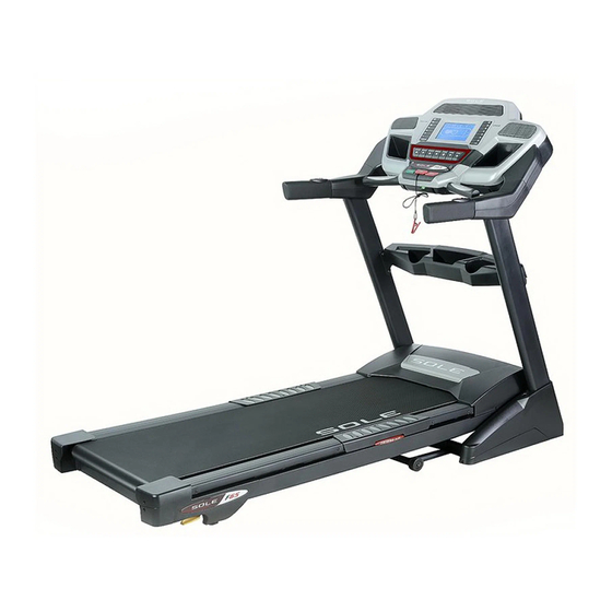
OWNER'S MANUAL
F63 / F65 Treadmill
Please carefully read this entire manual
before operating your new treadmill.
Before returning your Sole product to any retailer, or if you require any
assistance with assembly or technical support please call us first for
assistance at 866-697-6531. Thank you for your Sole purchase.
Advertisement
Table of Contents

Related Manuals for Sole Fitness F63


Summary of Contents for Sole Fitness F63
- Page 1 OWNER’S MANUAL F63 / F65 Treadmill Please carefully read this entire manual before operating your new treadmill. Before returning your Sole product to any retailer, or if you require any assistance with assembly or technical support please call us first for...
-
Page 2: Table Of Contents
TABLE OF CONTENTS Product Registration Important Safety Instructions Important Electrical Information Important Operation Instructions Assembly instructions Folding Instructions Transport Instructions Operation of Your New Treadmill Programmable Features General Maintenance Service Checklist - Diagnosis Guide Manufacturer’s Limited Warranty Before returning your Sole product to any retailer, or if you require any assistance with assembly or technical support please call us first for assistance at 866-697-6531. -
Page 3: Product Registration
If you have any questions about your new product or questions about the warranty contact SOLE Fitness at 1-866-780-SOLE (7653). If you have a technical problem with your new treadmill contact SOLE technical service at 866-MYSOLE1 (1-866-697-6531). -
Page 4: Important Safety Instructions
„ Wear proper shoes. High heels, dress shoes, sandals or bare feet are not suitable for use on your treadmill. Quality athletic shoes are recommended to avoid leg fatigue. Remove tether cord after use to prevent unauthorized treadmill operation. SAVE THESE INSTRUCTIONS - THINK SAFETY! F63 / F65 TREADMILL... -
Page 5: Important Electrical Information
Whenever the adapter is used, it must be held in place by a metal screw. F63 / F65 TREADMILL... -
Page 6: Important Operation Instructions
The treadmill will stop, depending on speed, with a one to two step coast anytime the safety key is pulled off the console. Use the red Stop switch in normal operation. F63 / F65 TREADMILL... - Page 7 Vacuum Under Motor Cover & Clean & Inspect Deck Lubricate Deck Inspect Belt Tracking Check Wiring for Lubrication (Every 90 hours (Monthly) Adjust if Date (Every Other (Every Other Month) or sooner if dry) necessary Month) F63 / F65 TREADMILL...
-
Page 8: Hardware Step
F63 / F65 ASSEMBLY PACK CHECKLIST HARDWARE STEP 2 #128. M5 Speed Nuts Clip (6 pcs) HARDWARE STEP 3 #130. 5/16” x 1/2” Button Head Socket Bolt (8 pcs) HARDWARE STEP 5 #113. Ø10 x 2T #139. 3/8” x 1-3/4”... - Page 9 #75. Safety Key Button Head Socket Bolt (4 pcs) HARDWARE STEP 8 #120. 5 x 16mm Tapping Screw (6 pcs) ASSEMBLY TOOLS #131. Combination M5 Allen Wrench & Phillips Head Screw Driver #132. M6 L Allen Wrench F63 / F65 TREADMILL...
-
Page 10: Assembly Instructions
F63 / F65 ASSEMBLY INSTRUCTIONS ASSEMBLY STEP 1 See Page 10 for Illustration Remove the treadmill from the carton and position it aside on a smooth, level floor. The rear should be at least 3’ from any wall. Do not remove the Velcro belt until you have removed the plastic wrap and Styrofoam from beneath the unit. - Page 11 Before attaching the hardware to Step 5, make sure the cables you just connected don’t get pinched in between the steel tubing. If they do, this may cause issues that prevent the treadmill from operating properly. F63 / F65 TREADMILL...
- Page 12 Attach the Left (141 & 142) and Right (143 & 144) Upper and Lower Handlebar Covers to the top of the Upright Tubes (4 & 5) with six Sheet Metal Screws (175). Tighten with the Combination M5 Allen Wrench & Phillips Head Screw Driver (131). F63 / F65 TREADMILL...
- Page 13 Attach the Console mast covers (62 & 63) to the Frame Base (2) with six Tapping Screws (120). Tighten screws using the Combination M5 Allen Wrench & Phillips Head Screw Driver (131). F63 / F65 TREADMILL...
-
Page 14: Folding Instructions
*At the rear roller area to relieve pressure on the ƒ locking system. TRANSPORTATION INSTRUCTIONS The treadmill is equipped with transport wheels that are engaged when the treadmill is folded. After folding simply roll the treadmill away. F63 / F65 TREADMILL... -
Page 15: Operation Of Your New Treadmill
RATE SENSORS F65 CONSOLE COOLING FANS SPEED QUICK KEYS INCLINE QUICK KEYS SPEAKER SPEAKER FAN POWER SWITCH DOT MATRIX DISPLAY DISPLAY BUTTON CONTROL KEYS AUDIO IN JACK HEADPHONE JACK (MP3, CD, OR SMARTPHONE) CONTACT HEART RATE SENSORS F63 / F65 TREADMILL... - Page 16 GETTING STARTED F63 / F65 CONSOLES Power the treadmill on by plugging it into an appropriate wall outlet, then turn on the power switch located at the front of the treadmill below the motor hood. Ensure that the Safety Key is installed, as the treadmill will not power on without it (see assembly step 7 for reference).
-
Page 17: Incline Feature
You may also choose a more rapid increase / decrease by selecting desired key, 1, 3, 6, 9, 12, 14 and 15, on left hand side of console (incline). „ The Incline Window display will indicate incline position as adjustments are made. F63 / F65 TREADMILL... - Page 18 DOT MATRIX CENTER DISPLAY Twenty columns of dots (8 high) indicate each segment of a workout for the F63 and eighteen columns of dots (8 high) indicate each segment of a workout for the F65. The dots are only to show an approximate level (speed/incline) of effort.
- Page 19 Stop, Enter and Display keys for 5 seconds; the display will show: Display mode - On. Use any of the Program, Incline or Speed 5 keys to change the setting to Off then press Enter. F63 / F65 TREADMILL...
-
Page 20: Programmable Features
PROGRAMMABLE FEATURES The F63 / F65 have ten built-in programs: one Manual program, five preset profiles (P1-P5), two user defined programs (U1 & U2) and two Heart Rate programs (HR1 & HR2). Hill The Hill program simulates going up and down a hill. The workload will steadily increase and then decrease during the program. - Page 21 6. Press Start to begin the program. The program will begin with a 3 minute warm-up. If you want to bypass this and go directly to the beginning of the program, press Start again. F63 / F65 TREADMILL...
- Page 22 Examples: If you increase your current speed 1 mph, the remaining segment speeds will increase by 1 mph. If you decrease your current speed .5 mph, the remaining segment speeds will decrease by .5 mph, etc. F63 / F65 TREADMILL...
- Page 23 80% or 60%, respectively, of your MHR on a schedule approved by your physician. Consult your physician before participating in any exercise program. F63 / F65 TREADMILL...
- Page 24 If you are feeling tired and sluggish, it is because your body needs a break. In this condition, your pace will feel harder. Again, this will show up in your RPE and you will train at the proper level for that day. F63 / F65 TREADMILL...
- Page 25 Another Individual wearing a transmitter within 3’ of your machine’s console. If you continue to experience problems contact your dealer. WARNING! - DO NOT USE THE HEART RATE PROGRAM IF YOUR HEART RATE IS NOT REGISTERING PROPERLY ON THE TREADMILL’S DISPLAY! F63 / F65 TREADMILL...
- Page 26 This process is automatic and could take upwards of five minutes, depending on how far your HR needs to go and what kind of physical shape you are in. People who are more fit will take longer to reach the target. F63 / F65 TREADMILL...
-
Page 27: Belt Adjustments
- located under the motor cover - that connects the motor to the front roller. If that belt is loose it feels similar to the walking belt being loose. Tightening the motor belt should be done by a trained service person. F63 / F65 TREADMILL... -
Page 28: Tread-Belt Tracking Adjustment
Adjustments will become less of a maintenance concern as the belt is used. Proper belt tracking is an owner responsibility common with all treadmills. ATTENTION: DAMAGE TO THE RUNNING BELT RESULTING FROM IMPROPER TRACKING / TENSION ADJUSTMENTS IS NOT COVERED UNDER THE SOLE WARRANTY. F63 / F65 TREADMILL... - Page 29 Do not lubricate with anything other than Sole Fitness approved lubricant. Your treadmill comes with one tube of “Lube” and extra tubes can be ordered directly from Sole Fitness or your authorized Sole Fitness dealer. You may also use a Lube-n-Walk kit that can be purchased through both aforementioned sellers.
-
Page 30: Service Checklist - Diagnosis Guide
(on a cold day) while Instructions on page 3. walking/running House circuit breaker trips, but not Need to replace the house breaker with a “High In-rush current” type breaker (see page 3 for details) the treadmill circuit breaker F63 / F65 TREADMILL... - Page 31 D. Security - Allows you to lock the keypad so no unauthorized use of the machine is allowed. When the child lock is enabled, the console will not allow the keypad to operate unless you press and hold the Start and Enter buttons for 3 seconds to unlock the console. Exit F63 / F65 TREADMILL...
-
Page 32: Manufacturer's Limited Warranty
Submit all service requests including serial number, contact information and a brief description of the problem online at www.soletreadmills. com/technical.php?p=service. If you have any questions about your new product or questions about the warranty contact SOLE Fitness at 1-866-780-SOLE (7653). If you have a technical problem with your new treadmill contact SOLE technical service at 866-MYSOLE1 (697-6531). - Page 33 Before returning your Sole product to any retailer, or if you require any assistance with assembly or technical support please call us first for assistance at 866-697-6531. Thank you for your Sole purchase.
- Page 34 F63 / F65 TREADMILL...
Need help?
Do you have a question about the F63 and is the answer not in the manual?
Questions and answers