
Related Manuals for Xantech EN85K Ensemble


Summary of Contents for Xantech EN85K Ensemble
- Page 1 INSTALLATION INSTRUCTIONS EN85K Ensemble Surface Mount / TV Mount / Flush Mount/ Shelf Mount Plasma LCD / LED / CFL Friendly Convertible IR Receiver Kit...
-
Page 2: Specifications
® DESCRIPTION The EN85K Ensemble is a convertible IR Receiver Kit that can be adapted to almost any surface mount, flush mount or shelf mount application. It includes all of the parts necessary for installing a single-room IR Repeater System for controlling a TV, Audio/Video Receiver, Blu-ray player, Cable Box, Satellite Re- ceiver...just about any IR controlled A/V home entertainment device. -
Page 3: What's Included
® WHAT’S INCLUDED The unique design of the EN85K allows the EN85 IR Receiver to be adapted to almost any surface mount, flush mount or shelf mount application using the in- cluded adapters. The EN85 can be mounted directly to flat panel TVs, placed on a shelf or mounted in a cabinet door for convenient armchair control of hidden audio/video components. - Page 4 ® READ THIS BEFORE YOU DO ANYTHING! FOUR IMPORTANT CONSIDERATIONS Where is the IR Receiver going to be located? The IR Receiver must be ‘line-of-sight’ to the remote control being used to be able to control the system audio/video components. This location should be in a convenient spot in front of the user when seated in a typical location for watching TV or listening to music.
-
Page 5: Installing The Ir Receiver
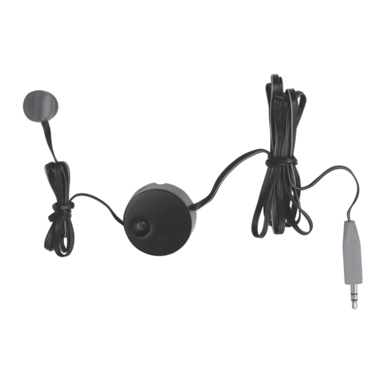
® INSTALLING THE IR RECEIVER Front of TV Attach with Adhesive Attach with Adhesive To Connecting Block RCVR Jack EN85 EN85 IR Receiver Electronics Module 8” Ribbon Cable Figure 1 - Surface Mount - Flat Panel TV SURFACE MOUNT The first, and easiest, option is to mount the IR Receiver on the front frame of a flat panel TV. - Page 6 ® Attach with Adhesive Attach with Adhesive Front of TV Front of TV EN85 EN85 Electronics Module Electronics Module Flat To Connecting To Connecting Block Block RCVR Jack RCVR Jack Attach with Adhesive EN85 Ridged End Flat End TV Mount Adapter EN85 Attach with Attach with Adhesive...
- Page 7 ® Wide Gap Lens Ribbon Cable IR Receiver Base Lock At Top Pass-Through Tabletop Adapter Base Lock Top Inside Base Locks Electronics Module Socket 8” Ribbon Cable Electronics Module Ribbon Cable ‘Bottom Notch’ IR Receiver Base Lock Pass-Through Base Lock Tabletop Adapter Base - Inside Lens To Connecting...
- Page 8 ® Cabinet Door Cabinet Door Pinch Adapter Locks together 11/16” (17.4mm) so they will slide through hole Diameter Hole in cabinet door. 11/16” (17.4mm) Diameter Hole Adapter Bezel 5/8” (15.9mm) Door Panel Figure 9 - Flush Mount Adapter - Figure 10 - Flush Mount Adapter - 11/16” Hole Install Adapter FLUSH MOUNT ADAPTER...
- Page 9 ® Cabinet Door Cabinet Door Flush Mount Adapter Bezel Insert IR Receiver into Flush Mount Adapter until it snaps into place Ribbon Cable Ribbon Cable Allow ~1” (25mm) clearance behind the back of a 5/8” (15.9mm) thick cabinet door for the Adapter Locks with the cabinet door closed. Figure 11 - Flush Mount Adapter - Figure 12 - Flush Mount Adapter - Adapter Installed...
-
Page 10: Typical Connections
® TYPICAL CONNECTIONS 781ERGPS Satellite Receiver To 120 V AC Hand Held (unswitched) 283D Emitter Remote 789-44 IR Photodiode & Connecting Block Red Talkback LED EN85 Micro Receiver mounts directly on a 283D Emitter flat panel TV frame or to one of the included +12 VDC A/V Receiver To extend wire length,... - Page 11 ® 6. Connect the Emitter(s) to the Connecting Block. (Connect the yellow IR Emitter plug to one of the yellow Connecting Block jacks.) Repeat for all Emitters. 7. Connect the 781ERGPS Power Supply to the 12VDC jack on the 789-44 Connecting Block. Connect the Power Supply to an UNSWITCHED AC outlet. To test, point an IR Remote at the EN85 IR Receiver. Press a specific function button on the remote (Cable/Satellite ON/OFF for example). The IR Receiver and all connected Emitters should flash red, and the selected component should respond to the command (Cable/Satellite ON/OFF). If any of that didn’t happen, check IR system connections and try again. If the system still hasn’t responded, check the Troubleshooting section at the end of this manual.
- Page 12 ® Use unshielded, 3 conductor stranded wire, per the table below, when extending the plug end of the IR Receiver Ribbon Cable. (4 conductor provides an extra wire for back-up if one of the conductors gets damaged.) IR WIRE LENGTH IR WIRE GAUGE UP TO 200’ (61m) 24 AWG UP TO 600’ (183m) 22 AWG UP TO 2000’ (610m) 20 AWG UP TO 5000’ (1524m) 18 AWG Figure 16 - 3.5mm Stereo Mini Plug & Wire Pin-Out When adding wire length, confirm that the IR Signal, +12VDC and GND wires are properly connected to both the IR Receiver and Connecting Block (Signal to Signal; +12 to +12; GND to GND). Improper connection will affect performance and possibly damage the IR Receiver. The EN85K Warranty does not cover this type of damage. Connections must be made as illustrated. To extend the Emitter wires to a more distant location, you may splice in 2-conductor wire, in the wire gauges shown above, as needed.
- Page 13 Installation combines the connections described in the previous Single Room and Extending the Wire sections. The Main Room IR Receiver gets connected using the red, 3.5mm mini ‘IR RCVR’ jack on the 789-44 Connecting Block and the multi-room receiver(s) get connected to the screw terminals on the Connecting Block. Figure 18 Xantech manufactures a variety of IR Receivers for different applications. Please visit xxx.xantech.com to find the IR Receiver that best fits your application.
- Page 14 ® IR Troubleshooting Guide NOTE: Due to the many variables in a given installation, the troubleshooting measures you may need to take can vary in different situations. Each installation is different due to the number of IR Receivers, length of wire runs, type of wire, amount of ambient IR noise present, etc….
- Page 15 ® Symptom #2: Talkback LED on IR Receiver (and/or Emitters) dimly lit or flickering. Cause Solution Signal and ground wires are Recheck wiring. reversed or shorted either at the Connecting Block or IR Receiver. Defective Emitter. Replace Emitter. Relatively high levels of ambient Reposition the IR Receiver away light noise.
- Page 16 ® Symptom #3: Talkback LED on IR Receiver (and/or Emitters) constantly on. Cause Solution Plasma Interference Plasma interference can be re- flected off of any item it comes into contact with within approx. 3 feet of the front of the display. Keeping this in mind, make sure that the IR Receiver is free from any object that might reflect Plasma interference...
- Page 17 ® Symptom #5: Intermittent IR control (i.e. buttons on remote need to be pressed multiple times) Cause Solution Plasma Interference. Plasma interference can be re- flected off of any item it comes into contact with within approx. 3 feet of the front of the display. Keeping this in mind, make sure that the IR Receiver is free from any object that might reflect Plasma interference...
- Page 18 ® Symptom 6: Emitters function but some (or all) components do not respond. Cause Solution Emitter placement is incorrect. Reposition the Emitter so that it is directly over the component’s IR eye. Shine a small flashlight into the front panel of the component to lo- cate the eye or consult the compo- nent’s owner’s manual for the exact location of the IR eye.
- Page 19 ® Symptom #7: Absolutely No Functionality (How to determine which component is at fault) Component to Test Instructions Verify Power Supply With a Multimeter, measure the DC Voltage of the Power Supply while it is connected to the Connecting Block. Put the negative lead of the meter on the terminal marked GND and the positive lead on the terminal marked 12VDC (or V). You should get a reading between 11.5VDC and 13.0VDC. If not, remove the supply from...
-
Page 20: Limited Warranty
® Limited Warranty Xantech warrants its products to be free of defects in materials or workmanship. ® This is a Limited Lifetime warranty from the date of purchase by the original consumer. Any products returned to Xantech and found to be defective by Xantech within the warranty period will be repaired or replaced, at Xantech’s option, at no charge. Xantech will not be responsible for the actual cost of installation or removal of the product, nor for any incidental or consequential damages.
Need help?
Do you have a question about the EN85K Ensemble and is the answer not in the manual?
Questions and answers