Lincoln Electric AIR VANTAGE 500 CUMMINS Operator's Manual
Hide thumbs
Also See for AIR VANTAGE 500 CUMMINS:
- Operator's manual (51 pages) ,
- Operator's manual (54 pages)
Table of Contents
Advertisement
IM826-
RETURN TO MAIN MENU
October, 2009
® ®
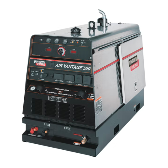
AIR VANTAGE 500 CUMMINS
11069, 11417
For use with machines having Code Numbers:
Safety Depends on You
Lincoln arc welding and cutting
equipment is designed and
built with safety in mind.
However, your overall safety
can be increased by proper
installation . . . and thoughtful
operation on your part. DO
NOT INSTALL, OPERATE OR
REPAIR THIS EQUIPMENT
WITHOUT READING THIS
MANUAL AND THE SAFETY
PRECAUTIONS CONTAINED
THROUGHOUT.
Most
importantly, think before you
act and be careful.
R
C
US
OPERATOR'S MANUAL
Copyright© Lincoln Global Inc.
• World's Leader in Welding and Cutting Products •
• Sales and Service through Subsidiaries and Distributors Worldwide •
Cleveland, Ohio 44117-1199 USA Tel: 216.481.8100 Fax: 216.486.1751 Web Site: www.lincolnelectric.com
Advertisement
Table of Contents
Troubleshooting

Subscribe to Our Youtube Channel
Related Manuals for Lincoln Electric AIR VANTAGE 500 CUMMINS


Summary of Contents for Lincoln Electric AIR VANTAGE 500 CUMMINS
- Page 1 IM826- RETURN TO MAIN MENU October, 2009 ® ® AIR VANTAGE 500 CUMMINS 11069, 11417 For use with machines having Code Numbers: Safety Depends on You Lincoln arc welding and cutting equipment is designed and built with safety in mind.
- Page 2 SAFETY WARNING CALIFORNIA PROPOSITION 65 WARNINGS For Diesel Engines: diesel engine exhaust and For Gasoline Engines: The engine exhaust from this some of its constituents are known to the State of product contains chemicals known to the State of California to cause cancer, birth defects, and other California to cause cancer, birth defects, or other reproductive harm.
-
Page 3: Electric Shock Can Kill
SAFETY ARC RAYS can burn. ELECTRIC SHOCK Use a shield with the proper filter and cover can kill. plates to protect your eyes from sparks and the rays of the arc when welding or observing open arc welding. Headshield 3.a. The electrode and work (or ground) circuits and filter lens should conform to ANSI are electrically “hot”... - Page 4 SAFETY CYLINDER may explode WELDING and CUTTING SPARKS can if damaged. cause fire or explosion. 7.a. Use only compressed cylinders 6.a. Remove fire hazards from the welding area. containing the correct shielding gas for the If this is not possible, cover them to prevent process used and properly operating the welding sparks from starting a fire.
- Page 5 SAFETY 6. Eloigner les matériaux inflammables ou les recouvrir afin de PRÉCAUTIONS DE SÛRETÉ prévenir tout risque d’incendie dû aux étincelles. Pour votre propre protection lire et observer toutes les instructions 7. Quand on ne soude pas, poser la pince à une endroit isolé de et les précautions de sûreté...
- Page 6 Lincoln Electric for advice or information about their use of our products. We respond to our customers based on the best information in our possession at that time. Lincoln Electric is not in a position to warrant or guarantee such advice, and assumes no liability, with respect to such information or advice.
-
Page 7: Table Of Contents
Connection of Lincoln Electric Wire Feeders ........ - Page 8 TABLE OF CONTENTS Accessories ..............Section C Optional Field Installed Accessories .
-
Page 9: Installation
INSTALLATION TECHNICAL SPECIFICATIONS - AIR VANTAGE® 500 CUMMINS (K2325-1) INPUT - DIESEL ENGINE Make /Model Description Speed (RPM) Displacement Starting Capacities System Cummins 4 cylinder High Idle 1900 199 cu. in 12VDC battery Fuel B3.3 56HP (42 kw) Low Idle 1425 (3.3L) &... -
Page 10: Safety Precautions
INSTALLATION Read this entire installation section before you start LOCATION / VENTILATION installation. The welder should be located to provide an unrestricted flow of SAFETY PRECAUTIONS clean, cool air to the cooling air inlets and to avoid restricting the cooling air outlets. Also, locate the welder so that the engine exhaust fumes are properly vented to an outside area. -
Page 11: Lifting
INSTALLATION LIFTING HIGH TEMPERATURE OPERATION The AIR VANTAGE® 500 lift bale should be used to lift the At temperatures above 40°C (104°F), output voltage derating machine. The AIR VANTAGE® 500 is shipped with the lift bale may be necessary. For maximum output current ratings, derate retracted. -
Page 12: Pre-Operation Engine And Compressor Service
INSTALLATION PRE-OPERATION ENGINE AND ENGINE COOLANT COMPRESSOR SERVICE WARNING WARNING HOT COOLANT can burn skin. READ the engine and compressor operating and maintenance instructions supplied with this machine. •Do not remove cap if radiator is hot. • Keep hands away from the engine muffler or HOT engine parts. -
Page 13: Muffler Outlet Pipe
INSTALLATION The AIR VANTAGE® 500 is shipped with the negative battery WELDING TERMINALS cable disconnected. Before you operate the machine, make sure The AIR VANTAGE® 500 is equipped with a toggle switch for the Engine Switch is in the OFF position and attach the selecting "hot"... -
Page 14: Remote Control
INSTALLATION REMOTE CONTROL STANDBY POWER CONNECTIONS The AIR VANTAGE® 500 is suitable for temporary, standby or OUTPUT emergency power using engine manufacturer’s recommended maintenance schedule. The AIR VANTAGE® 500 is equipped with a 6-pin and a 14-pin connector. The 6-pin connector is for connecting the K857 or The AIR VANTAGE®... - Page 15 INSTALLATION 2. Take necessary steps to assure load is limited to the capacity 3. Install a 50 amp 120/240 VAC plug (NEMA Type 14-50) to the double-pole circuit breaker using No. 6, 4 conductor cable of of the AIR VANTAGE® 500 by installing a 50 amp, 240 VAC double pole circuit breaker.
-
Page 16: Connection Of Lincoln Electric Wire Feeders
INSTALLATION CONNECTION OF LINCOLN ELECTRIC WIRE FEEDERS WARNING Shut off welder before making any electrical connections. ------------------------------------------------------------------------------------- CONNECTION OF LN-7, LN-8 OR LN-742 TO THE AIR VANTAGE® 500 • Shut the welder off. • Connect the LN-7, LN-8 OR LN-742 per instructions on the appropriate connection diagram in the DIAGRAMS section. - Page 17 INSTALLATION CONNECTION OF THE LN-25 TO THE AIR CONNECTION OF MAGNUM SC SPOOL GUN TO VANTAGE® 500 THE AIR VANTAGE® 500 (SEE SECTION F) The LN-25 with or without an internal contactor may be used with the AIR VANTAGE® 500. See the appropriate connection diagram in the DIAGRAMS section.
-
Page 18: Operation
OPERATION SAFETY INSTRUCTIONS GENERAL DESCRIPTION Read and understand this entire section before operating The AIR VANTAGE® 500 is a diesel engine-driven welding power source. The machine uses a brush type alternating current your AIR VANTAGE® 500. generator for DC multi-purpose welding, for 120/240 VAC single phase and 240V three phase auxiliary standby power. -
Page 19: Controls And Settings
OPERATION CONTROLS AND SETTINGS All welder and engine controls are located on the case front panel. Refer to Figure B.1 and the explanations that follow. Figure B.1 Case Front Panel Controls ENGINE CONTROLS (Items 1 through 9) 3. HOUR METER The hour meter displays the total time that the engine has been 1. - Page 20 OPERATION 6. OIL PRESSURE GAUGE c. When welding ceases and the AC power load is turned off, a fixed time delay of approximately 12 seconds The gauge displays the engine oil pressure when the engine is starts. running. d. If the welding or AC power load is not restarted before the end of the time delay, the idler reduces the engine 7.
-
Page 21: Auxiliary Power Controls
OPERATION WELDING CONTROLS (Items 10 through 19) 10. OUTPUT CONTROL: The OUTPUT dial is used to preset the output voltage or current as displayed on the digital meters for the CV-WIRE mode: In this mode, turning the ARC CONTROL knob four welding modes. -
Page 22: Air Compressor Controls
OPERATION 20. CIRCUIT BREAKERS ENGINE OPERATION These circuit breakers provide separate overload current STARTING THE ENGINE protection for each 120V circuit at the 240V single phase receptacle, each 120V single phase receptacle, the 240V three 1. Open the engine compartment door and check that the fuel phase receptacle, the 120VAC in the 14-Pin connector, the shutoff valve located to the left of the fuel filter housing is in the 42VAC in the 14-Pin connector and battery circuit overload... -
Page 23: Break-In Period
OPERATION BREAK-IN PERIOD CC-STICK MODE The CC-STICK position of the MODE switch is designed for The engine used to supply power for your welder is a heavy duty, horizontal, vertical-up and over head welding with all types of industrial engine. It is designed and built for rugged use. It is very electrodes, especially low hydrogen. -
Page 24: Air Vantage® Settings When Using K930-2 Tig Module
OPERATION AIR VANTAGE® 500 SETTINGS WHEN USING THE K930-2 TIG MODULE • Set the WELD MODE switch to the “Touch Start Tig 20-250 Setting”. • Set the IDLER switch to the “AUTO” position. • Set the WELDING TERMINALS switch to the “Remotely Controlled”... -
Page 25: Cv-Wire Mode
OPERATION CV-WIRE MODE The auxiliary power capacity is 12,000 watts of 60 Hz, single Connect a wire feeder to the AIR VANTAGE® 500 and set welder phase power or 20,000 watts of 60Hz, three phase power. The controls according to the instructions listed earlier in this section. auxiliary power capacity rating in watts is equivalent to volt- amperes at unity power factor. - Page 26 OPERATION TABLE B.4 AIR VANTAGE® 500 SIMULTANEOUS WELDING AND POWER LOADS WELD 1 PHASE 3 PHASE BOTH 1 AND 3 PHASE AMPS WATTS AMPS WATTS AMPS WATTS AMPS 12,000 20,000 ------ 12,000 17,800 ------ PLUS 12,000 14,000 ------ 12,000 12,000 12,000 ------ 10,000...
-
Page 27: Accessories
The use of an arc welder for pipe thawing is not approved by the CSA, nor is it recommended or supported by Lincoln Electric. ------------------------------------------------------------------------------------- K2354-1 Air Dryer Kit-Minimizes water content in supply air. -
Page 28: Maintenance
MAINTENANCE SAFETY PRECAUTIONS COMPRESSOR MAINTENANCE Refer to the “Routine Maintenance” section of the compressor owner’s manual for the recommended maintenance schedule of WARNING the following: a. Compressor oil and filter. • Have a qualified technician do the maintenance and b. Compressor air filter. troubleshooting work. - Page 29 MAINTENANCE Service Instructions & Installation Tips For Engine Air Filter Donaldson filters with RadialSeal Sealing ™ Check the Old Release the Technology are self-aligning, self-centering, Seal Carefully Filter for Leak Clues and self-sealing. A new filter has a dry Visually inspect the old filter for any signs Unlatch and remove the service lubricant to aid installation.
-
Page 30: Fuel Filters
MAINTENANCE FUEL FILTERS BATTERY HANDLING GASES FROM BATTERY can explode. WARNING • Keep sparks, flame and cigarettes away from battery. When working on the fuel system To prevent EXPLOSION when: • Keep naked lights away, do not smoke ! • INSTALLING A NEW BATTERY - disconnect •... -
Page 31: Charging The Battery
MAINTENANCE CHARGING THE BATTERY GFCI RECEPTACLE TESTING AND RESETTING PROCEDURE When you charge, jump, replace, or otherwise connect battery cables to the battery, be sure the polarity is correct. Improper polarity can damage the charging circuit. The AIR VANTAGE® The GFCI receptacle should be properly tested at least once 500 positive (+) battery terminal has a red terminal cover. -
Page 32: How To Use Troubleshooting Guide
HOW TO USE TROUBLESHOOTING GUIDE WARNING Service and Repair should only be performed by Lincoln Electric Factory Trained Personnel. Unauthorized repairs performed on this equipment may result in danger to the technician and machine operator and will invalidate your factory warranty. -
Page 33: Troubleshooting
TROUBLESHOOTING Observe all Safety Guidelines detailed throughout this manual RECOMMENDED PROBLEMS POSSIBLE COURSE OF ACTION (SYMPTOMS) CAUSE ENGINE PROBLEMS 1. Contact your Local Lincoln Authorized Major Physical or Electrical Damage is Evident. Field Service Facility. Engine will not crank 1. Battery low. 2. - Page 34 TROUBLESHOOTING PROBLEMS POSSIBLE RECOMMENDED (SYMPTOMS) CAUSE COURSE OF ACTION FUNCTION PROBLEMS 1. Faulty battery . Battery does not stay charged. 2. Faulty engine alternator. 3. Loose or broken lead in charging circuit. 4. Loose fan belt may need tightening. 1. Idler switch in HIGH idle position, make Engine will idle...
- Page 35 TROUBLESHOOTING PROBLEMS RECOMMENDED POSSIBLE (SYMPTOMS) COURSE OF ACTION CAUSE FUNCTION PROBLEMS Engine goes to low idle but does not stay at 1. Faulty Peripheral PCB, Pull Coil/Battery low idle. PCB or Weld Control PCB. No welding output or auxiliary output. 1.
- Page 36 DIAGRAMS ENHANCED DIAGRAM AIR VANTAGE® 500 CUMMINS...
- Page 37 DIAGRAMS CONNECTION DIAGRAM: AIR VANTAGE® 500 CUMMINS...
- Page 38 DIAGRAMS CONNECTION DIAGRAM: AIR VANTAGE® 500 CUMMINS...
- Page 39 DIAGRAMS CONNECTION DIAGRAM AIR VANTAGE® 500 CUMMINS...
- Page 40 DIAGRAMS CONNECTION DIAGRAM AIR VANTAGE® 500 CUMMINS...
- Page 41 DIAGRAMS CONNECTION DIAGRAM AIR VANTAGE® 500 CUMMINS...
- Page 42 DIAGRAMS CONNECTION DIAGRAM AIR VANTAGE® 500 CUMMINS...
- Page 43 DIAGRAMS CONNECTION DIAGRAM AIR VANTAGE® 500 CUMMINS...
- Page 44 DIAGRAMS CONNECTION DIAGRAM AIR VANTAGE® 500 CUMMINS...
- Page 45 DIAGRAMS F-10 F-10 CONNECTION DIAGRAM AIR VANTAGE® 500 CUMMINS...
- Page 46 DIAGRAMS F-11 F-11 CONNECTION DIAGRAM AIR VANTAGE® 500 CUMMINS...
- Page 47 DIAGRAMS F-12 F-12 CONNECTION DIAGRAM AIR VANTAGE® 500 CUMMINS...
- Page 48 DIAGRAMS F-13 F-13 DIMENSION PRINT AIR VANTAGE® 500 CUMMINS...
- Page 49 Do not touch electrically live parts or Keep flammable materials away. Wear eye, ear and body protection. WARNING electrode with skin or wet clothing. Insulate yourself from work and ground. Spanish No toque las partes o los electrodos Mantenga el material combustible Protéjase los ojos, los oídos y el AVISO DE bajo carga con la piel o ropa...
- Page 50 Keep your head out of fumes. Turn power off before servicing. Do not operate with panel open or WARNING Use ventilation or exhaust to guards off. remove fumes from breathing zone. Spanish Los humos fuera de la zona de Desconectar el cable de No operar con panel abierto o AVISO DE respiración.
- Page 51 World’s Leader in Welding and Cutting Products • Sales and Service through Subsidiaries and Distributors Worldwide • Cleveland, Ohio 44117-1199 USA Tel: 216.481.8100 Fax: 216.486.1751 Web Site: www.lincolnelectric.com...
Need help?
Do you have a question about the AIR VANTAGE 500 CUMMINS and is the answer not in the manual?
Questions and answers