Table of Contents
Advertisement
Quick Links
OPERATOR'S MANUAL
1/2 RACK VOLTAGE/CURRENT-STABILIZED DC SOURCE
KEPCO INC.
An ISO 9001 Company.
IMPORTANT NOTES:
1)
This manual is valid for the following Model and associated serial numbers:
MODEL
2)
A Change Page may be included at the end of the manual. All applicable changes and
revision number changes are documented with reference to the equipment serial num-
bers. Before using this Instruction Manual, check your equipment serial number to identify
your model. If in doubt, contact your nearest Kepco Representative, or the Kepco Docu-
mentation Office in New York, (718) 461-7000, requesting the correct revision for your par-
ticular model and serial number.
3)
The contents of this manual are protected by copyright. Reproduction of any part can be
made only with the specific written permission of Kepco, Inc.
Data subject to change without notice.
©2016, KEPCO, INC
P/N 243-0970-r6
KEPCO, INC. 131-38 SANFORD AVENUE FLUSHING, NY. 11355 U.S.A. TEL (718) 461-7000 FAX (718) 767-1102
SERIES BHK-MG
40 WATT POWER SUPPLY
MODEL
BHK-MG 40 WATT
POWER SUPPLY
ORDER NO.
SERIAL NO.
email: hq@kepcopower.com World Wide Web: http://www.kepcopower.com
REV. NO.
REV. NO.
KEPCO
THE POWER SUPPLIER™
®
Advertisement
Chapters
Table of Contents

Related Manuals for KEPCO BHK-MG Series


Summary of Contents for KEPCO BHK-MG Series
-
Page 1: Watt Power Supply
Data subject to change without notice. KEPCO ® ©2016, KEPCO, INC P/N 243-0970-r6 THE POWER SUPPLIER™ KEPCO, INC. 131-38 SANFORD AVENUE FLUSHING, NY. 11355 U.S.A. TEL (718) 461-7000 FAX (718) 767-1102 email: hq@kepcopower.com World Wide Web: http://www.kepcopower.com... -
Page 3: Declaration Of Conformity
Voltage Dips, Fast Transient_EFT, EN61000-4-5, IEC61000-4-3, IEC61000-4-6, ESD, Surge Immunity, Radiated Immunity IEC61000-4-8 (designed to meet), Conducted Immunity, Magnetic Field Immunity (designed to meet) Manufacturer's Name: KEPCO, INC. Manufacturer's Address: 131-38 SANFORD AVENUE FLUSHING NY 11355 Importer's Name: Importer's Address: Type of Equipment:... - Page 4 There are no user or operator serviceable parts within the product enclosure. Refer all servicing to qualified and trained Kepco service technicians. 228-XXXX COND/CONFORM 030916...
- Page 5 SAFETY INSTRUCTIONS 1. Installation, Operation and Service Precautions This product is designed for use in accordance with EN 61010-1 and UL 3101 for Installation Category 2, Pollution Degree 2. Hazardous voltages are present within this product during normal operation. The prod- uct should never be operated with the cover removed unless equivalent protection of the operator from accidental contact with hazardous internal voltages is provided: There are no operator serviceable parts or adjustments within the product enclosure.
-
Page 7: Table Of Contents
TABLE OF CONTENTS SECTION PAGE SECTION 1 - INTRODUCTION Scope of Manual ............................. 1-1 General Description..........................1-1 Specifications ............................1-2 Features ..............................1-9 1.4.1 Local Control............................1-9 1.4.2 Remote Control..........................1-9 1.4.2.1 Digital Programming ........................1-9 1.4.2.2 Analog Programming ........................1-9 1.4.2.3 Analog Readback......................... - Page 8 TABLE OF CONTENTS SECTION PAGE 3.2.2 Turning the Power Supply On......................3-4 3.2.3 Error Conditions ..........................3-5 3.2.4 Setting Local Mode ........................... 3-5 3.2.5 Adjusting LCD Contrast ........................3-6 3.2.6 Enabling/Disabling Audible Beeps ....................3-6 3.2.7 Enabling/Disabling DC Output Power ....................3-6 3.2.7.1 Disabling DC Output ........................
- Page 9 TABLE OF CONTENTS SECTION PAGE 3.7.3.6 Instrument Subsystem ......................... 3-24 3.7.3.7 STATus Subsystem ........................3-24 3.7.3.8 System Subsystem ........................3-24 3.7.3.9 TRIGger subsystem ........................3-24 3.7.3.10 [SOURce:]VOLTage and [SOURce:]CURRent Subsystems ............3-24 3.7.3.11 CALibrate Subsystem ........................3-24 3.7.4 Program Message Structure......................3-26 3.7.4.1 Keyword ............................
- Page 10 TABLE OF CONTENTS SECTION PAGE 4.5.4 Calibration Procedure ........................4-7 Changing the Calibration Password ....................... 4-9 Restoring Previous Calibration Values ....................4-9 Restoring Factory Calibration Values ..................... 4-9 Calibration Storage ..........................4-10 APPENDIX A - IEEE 488.2 COMMAND/QUERY DEFINITIONS Introduction ............................. A-1 *CLS —...
- Page 11 TABLE OF CONTENTS SECTION PAGE B.31 [SOURce:]LIST:VOLTage Command ..................... B-7 B.32 [SOURce:]LIST:VOLTage? Query ......................B-7 B.33 [SOURce:]LIST:VOLTage:POINts? Query ..................... B-7 B.34 MEASure[:SCALar]:CURRent[:DC]? Query ................... B-9 B.35 MEASure:VOLTage[:SCALar][:DC]? Query ................... B-9 B.36 OUTPut[:STATe] Command ........................B-9 B.37 OUTPut[:STATe]? Query ........................B-10 B.38 [SOURce:]CURRent[:LEVel][:IMMediate][:AMPlitude] Command............
- Page 12 TABLE OF CONTENTS SECTION PAGE B.81 SYSTem:ERRor:CODE:ALL? Query ...................... B-18 B.82 SYSTem:KLOCk Command........................B-18 B.83 SYSTem:KLOCk? Query ........................B-19 B.84 SYSTem:PASSword:CENable Command ....................B-19 B.85 SYSTem:PASSword:CDISable Command ..................... B-19 B.86 SYSTem:PASSword:NEW Command ....................B-19 B.87 SYSTem:PASSword:STATe? Query....................... B-19 B.88 SYSTem:SECurity:IMMediate Command ....................B-19 B.89 SYSTem:VERSion? Query ........................
- Page 13 RA 24 Rack Adapter with two 1/2 Rack BHK-MG 40W Units ..............1-8 Connector A2J5 Location ........................... 1-10 BHK-MG Series, Front Panel Controls, Indicators and Connectors............2-1 BHK-MG Series, Rear Panel Controls and Connections ................2-3 LCD Power On Defaults ..........................2-7 Local Sensing, Slow Mode Selected, Grounding Network Connected, Floating Output (Factory Default Configuration)..................
-
Page 14: List Of Figures
LIST OF FIGURES FIGURE TITLE PAGE Programming Voltage..........................B-14 Using Status Commands and Queries ....................... B-15 Using System Commands and Queries ..................... B-19 viii BHK 1/2 RACK 030916... - Page 15 LIST OF TABLES TABLE TITLE PAGE Model Parameters ............................1-2 BHK-MG 40W Specifications ........................1-2 Connector A2J5 Signal Descriptions ......................1-12 Equipment Supplied ............................1-13 Accessories ..............................1-14 Safety Symbols ............................1-14 Controls, Indicators, and Connectors ......................2-2 IEEE 488 Port Connector Pin Assignments ....................2-4 Status and Remote On/Off Port Connector Pin Assignments ..............2-4 RS 232C PORT Input/Output Pin Assignments ..................2-5 External Trigger Port Pin Assignments .......................2-5 Rear Output Terminal Strip A6TB1, Terminal Assignments ................2-5...
-
Page 17: Safety Messages
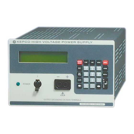
There are no operator serviceable parts inside the case. Service must be referred to authorized personnel. Using the power supply in a manner not specified by Kepco. Inc. may impair the protection provided by the power supply. Observe all safety precautions noted throughout this manual. The following table lists sym- bols used on the power supply or in this manual where applicable. - Page 18 FIGURE 1-1. BHK-MG 40W SERIES PROGRAMMABLE POWER SUPPLY BHK-MG030916...
-
Page 19: Section 1 - Introduction
Although designed as a stand-alone bench top unit, the half-rack cross section permits mount- ing two units side by side in a standard 19-inch wide rack using Kepco’s RA 24 Rack Adapter (see Figure 1-3). Connections can be made at both rear output terminals (recommended for rack mounted configurations) and front output terminals (recommended for bench applications). -
Page 20: Specifications
See Note 166.7 See Note BHK 2000-20MG 0 - 2000 0 - 20 See Note 666.7 See Note NOTE: Contact Kepco for assistance. TABLE 1-2. BHK-MG 40W SPECIFICATIONS SPECIFICATION RATING/DESCRIPTION CONDITION INPUT CHARACTERISTICS a-c Voltage nominal (switch select- 115/230V a-c... - Page 21 TABLE 1-2. BHK-MG 40W SPECIFICATIONS (Continued) SPECIFICATION RATING/DESCRIPTION CONDITION OUTPUT CHARACTERISTICS (CONTINUED) Load effect Voltage 0.005% E no load - full load Current 0.015% I short - full load Temperature effect Voltage 0.01% E Ambient temperature (per degree C) 0 to 50° C Current 0.02% I Time effect Voltage 0.01% E...
- Page 22 TABLE 1-2. BHK-MG 40W SPECIFICATIONS (Continued) SPECIFICATION RATING/DESCRIPTION CONDITION OUTPUT CHARACTERISTICS (CONTINUED) Withstand voltage (All models) 1350V a-c/1 min Between shorted inputs and chassis BHK 300-130MG 1950V d-c/1 min Between shorted outputs and chassis. BHK 500-80MG 2250V d-c/1 min BHK 1000-40MG 2800V d-c/1 min BHK 2000-20MG Chassis connection to ground...
- Page 23 TABLE 1-2. BHK-MG 40W SPECIFICATIONS (Continued) SPECIFICATION RATING/DESCRIPTION CONDITION OUTPUT CHARACTERISTICS (CONTINUED) Series Connection Automatic or Master-Slave For slave unit, use analog programming Operation, limited by the d-c only. isolation limit voltage Parallel Connection Automatic or Master-Slave For slave unit, use analog programming Operation only.
-
Page 24: Bhk 40W Series Power Supply, Mechanical Outline Drawing
FIGURE 1-2. BHK 40W SERIES POWER SUPPLY, MECHANICAL OUTLINE DRAWING (SHEET 1 OF 2) BHK-1/2-MG (OPR) 030916... - Page 25 FIGURE 1-2. BHK 40W SERIES POWER SUPPLY, MECHANICAL OUTLINE DRAWING (SHEET 2 OF 2) BHK-1/2-MG (OPR) 030916...
-
Page 26: Ra 24 Rack Adapter With Two 1/2 Rack Bhk-Mg 40W Units
FIGURE 1-3. RA 24 RACK ADAPTER WITH TWO 1/2 RACK BHK-MG 40W UNITS BHK-1/2-MG (OPR) 030916... -
Page 27: Features
FEATURES 1.4.1 LOCAL CONTROL Front panel keypad entries and an LCD type display are utilized for setting and/or adjusting out- put voltage and current under local control. The keypad's keys are organized to either directly execute commands, or to introduce a program that can either be run once or cycled. Calibration of the unit is facilitated by a password -protected, menu-driven procedure from the front panel. -
Page 28: Overvoltage/Overcurrent Protection
FIGURE 1-4. CONNECTOR A2J5 LOCATION 1.4.4 OVERVOLTAGE/OVERCURRENT PROTECTION Overvoltage and Overcurrent protection values can be individually programmed. The range for overvoltage and overcurrent values are 0 to 1.1 x E max, 0 to 1.1 x I max. If the output volt- age/current is maintained at or above the overvoltage/overcurrent protection value for more than 9ms, the protection circuit cuts the pass element off, discharges the output capacitor, trips the POWER circuit breaker to OFF and sends a flag on a dedicated line (status port connector). -
Page 29: Current Measurement Scale
1.4.8 FAST MODE/SLOW MODE SELECTION BHK-MG Series Power Supplies can be configured by external strapping for either slow mode operation with the internal output capacitor connected to the output, or fast mode operation with the internal output capacitor disconnected from the output. The slow mode (default state) is rec- ommended for voltage stabilization because of its low output noise and low recovery amplitude to a dynamically changing load. -
Page 30: Analog Readback And Flag Signals Available For Customer Use
g. Overload of the main or auxiliary power transformer. If input current of the main trans- former exceeds 1.1A a-c @ 115V a-c or 0.6A a-c @ 230V a-c, the input POWER circuit breaker is tripped to OFF, the pass element is cut off, the output capacitor is discharged, and a flag is sent to the Status Port connector. -
Page 31: Current Sink Capability
1.4.12 CURRENT SINK CAPABILITY BHK-MG 40W Series power supplies are able to sink up to 5% of the nominal current when in voltage mode and greater than 75% of the unit's maximum rated current when in current mode. The fixed current mode sink value is model dependent and has a tolerance of 10%. When the BHK-MG 40W is in sink mode, the unit displays the word “Sink”... -
Page 32: Accessories
There are no operator serviceable parts inside the case. Service must be referred to authorized personnel. Using the power supply in a manner not specified by Kepco. Inc. may impair the pro- tection provided by the power supply. Observe all safety precautions noted throughout this man- ual. -
Page 33: Section 2 - Installation
TERMINATIONS AND CONTROLS a). Front Panel: Refer to Figure 2-1 and Table 2-1. b). Rear Panel: Refer to Figure 2-2 and Table 2-1. FIGURE 2-1. BHK-MG SERIES, FRONT PANEL CONTROLS, INDICATORS AND CONNECTORS BHK-1/2-MG SERIES 030916... -
Page 34: Controls, Indicators, And Connectors
TABLE 2-1. CONTROLS, INDICATORS, AND CONNECTORS CONTROL, INDICATOR, FUNCTION CONNECTOR FRONT PANEL (See Figure 2-1.) A-C line indicator Lights to indicate unit turned on and a-c power applied. 2 x 16 character Liquid Display with LED backlight. Shows voltage, current mode, settings, menu, program, etc. -
Page 35: Bhk-Mg Series, Rear Panel Controls And Connections
FIGURE 2-2. BHK-MG SERIES, REAR PANEL CONTROLS AND CONNECTIONS BHK-1/2-MG SERIES 030916... -
Page 36: Ieee 488 Port Connector Pin Assignments
TABLE 2-2. IEEE 488 PORT CONNECTOR PIN ASSIGNMENTS CONNECTOR SIGNAL NAME FUNCTION I/O Line I/O Line I/O Line I/O Line End or Identify Data Valid NRFD Not Ready for Data NDAC Not Data Accepted Interface Clear Service Request Attention IEEE 488 SHIELD Shield PORT... -
Page 37: Rs 232C Port Input/Output Pin Assignments
TABLE 2-4. RS 232C PORT INPUT/OUTPUT PIN ASSIGNMENTS Adapter Cable (P/N KIT 219-0436) CONNECTOR SIGNAL NAME FUNCTION FUNCTION Return Signal Ground Not Used Not Used Receive Data Transmit Data Transmit Data Receive Data Data Terminal Ready (protocol not used) RS 232 PORT Return Signal Ground... -
Page 38: Source Power Requirements
TABLE 2-8. CURRENT PROGRAMMING TERMINAL STRIP A6TB3, TERMINAL ASSIGNMENTS TERMINAL SIGNAL NAME FUNCTION –10V –10V d-c reference voltage C(NINV) Noninverting input of uncommitted amplifier SGND Signal common C(+IN) Programming input for positive input signal +10V +10V d-c reference voltage C(INV) Inverting input of uncommitted amplifier C(FBK) Internal feedback resistor;... -
Page 39: Preliminary Operational Check
PRELIMINARY OPERATIONAL CHECK WARNING BEFORE APPLYING AC SOURCE POWER TO THE POWER SUPPLY, VERIFY THAT THE LINE VOLTAGE TO BE SUPPLIED MATCHES THE POSITION OF THE AC INPUT SELEC- TOR SWITCH AT THE REAR PANEL (FACTORY DEFAULT IS 115V). A simple operational check after unpacking and before equipment installation is advisable to ascertain whether the power supply has suffered damage resulting from shipping. -
Page 40: Installation
NOTE: If tolerances specified in the following steps are exceeded, refer to Section 4 and reca- librate the unit. Compare the programmed output voltage value with the voltage reading of the DVM; the difference between the two should not exceed 0.025% of the nominal voltage of the unit. Compare the voltage reading of the LCD with that of the DVM;... -
Page 41: Rack Mounting
2.6.2 RACK MOUNTING Using a Kepco RA 24 Rack Adapter, two 1/2 rack BHK-MG 40W units can be mounted in a 19- inch wide rack, after the bench-type feet are removed (see Figure 1-3). Optional slides for the rack adapter (see Table 1-5) can be used to improve access to the unit. -
Page 42: Power Supply/Load Interface
It is hoped that the preceding paragraphs will be of some assistance in most cases. For help in special applications or difficult problems, consult directly with Kepco's Application Engineering Department. 2.7.4... -
Page 43: Cable Recommendations
For sense cables (positive and negative) No. 22 AWG stranded wire is rec- ommended for each. For noisy environments, tied pair or twisted pair cables are recommended. It is recommended that cable length not exceed 50 feet; for longer cable lengths, contact Kepco. 2.7.5... -
Page 44: Local Sensing/Remote Sensing Select
FIGURE 2-4. LOCAL SENSING, SLOW MODE SELECTED, GROUNDING NETWORK CONNECTED, FLOATING OUTPUT (FACTORY DEFAULT CONFIGURATION) 2.7.5.1 LOCAL SENSING/REMOTE SENSING SELECT Local sensing (factory default configuration) is established by connecting terminals TB1-6 (+S) to TB1-7 (+OUT) and TB1-2 (–OUT) to TB1-3 (–S) (see Figure 2-4). The power supply is shipped with these connections installed for local sensing. -
Page 45: Positive Output, Negative Terminal Grounded
Table 2-9 lists the location of the internal jumpers and their function. This information is provided for reference purposes only, to indicate the configuration options available. Do not attempt to alter the jumper configuration. For assistance in changing any jumper-selected parameter con- tact Kepco Applications Engineering. 2-13 BHK-1/2-MG SERIES 030916... -
Page 46: Status Port
TABLE 2-9. INTERNAL JUMPER CONFIGURATION DEFAULT LOCATION JUMPER FUNCTION STATUS Not Installed For Service Personnel only. When installed (short circuit) a first time calibration will be initiated. Use this jumper only when necessary, then remove the jumper after calibration is initiated. Installed Enables input circuit breaker to trip when arcing at the output is detected. -
Page 47: Section 3 - Operation
SECTION 3 - OPERATION GENERAL This section explains how to operate the BHK-MG 40W Power Supply. The power supply can be operated either in Local mode using the front panel keypad and LCD (PAR. 3.2), or in Remote mode using SCPI commands via either the GPIB bus (PARs. 3.3, 3.7) or RS 232 bus (PAR. 3.5) or using analog programming via the rear panel terminals (PAR 3.8). -
Page 48: Keypad Functions
TABLE 3-1. LCD MESSAGES LOCATION MESSAGE DESCRIPTION Top left Loc/Rem Digital control status: either Remote or Local Shows that the unit is in sink mode and is absorbing energy either from the load or the internal output capacitor. The sink current is Top middle SINK model-dependent and appears on the second line of the display pre-... - Page 49 TABLE 3-2. KEY FUNCTIONS (CONTINUED) POWER SUPPLY REFERENCE DESCRIPTION STATUS ACTIVE PARAGRAPH Press to enter Menu commands: press repeatedly to scroll through Menu (1) 3.2.5, (2) 3.3.3 functions: (1) set LCD contrast, (2) GPIB address, (3) Baud Rate. (4) Loop (3) 3.5.1, (4) 3.5.4 Back Test (5) DCL control, (6) Power-Up Digital DC Output on/off, (7) (5) 3.3.2,...
-
Page 50: Turning The Power Supply On
When the power supply is turned on, the LCD briefly displays self test messages, then displays the power supply type on the top line (e.g., Kepco BHK 500) and GPIB addr. = nn on the bottom line, where BHK 500 is model BHK 500-80MG and nn is the GPIB address (factory default GPIB address = 6). -
Page 51: Error Conditions
0.000V (:_:_:) 0.000A 0.000V (:_:_:) 0.000A (a) Default Display State for OUT OFF (b) Default Display State for OUT ON @ Pwr-Up Selection (PAR. 3.2.7.4) at Pwr-Up Selection (PAR. 3.2.7.4) NOTE: (:_:_:) indicates blinking colon (:), Command Entry status (=_=_=) indicates blinking equal sign (=), Data Entry status FIGURE 3-1. -
Page 52: Adjusting Lcd Contrast
The BHK-MG incorporates a “keypad lockout” command which allows the LOCAL key to be dis- abled during remote operation, preventing inadvertent setting of the power supply to Local mode. When the keypad is locked, the LCD displays RwL in place of LOC. If the keypad is locked, it must be unlocked either by a remote command (see Appendix B, PAR. -
Page 53: Remote Shutdown Using External Trigger Port
3.2.7.3 REMOTE SHUTDOWN USING EXTERNAL TRIGGER PORT A temporary short between pin 2 and pin 1 of the External Trigger port (or if pin 2 is at TTL logic 1, applying a temporary logic 0 to pin 2 referenced to pin 1) produces a shutdown signal which immediately shuts down the power supply output: output is disabled and voltage and current are set to zero (1 LSB maximum for voltage, 20 LSBs maximum for current). -
Page 54: Setting Output Voltage Or Current
3.2.9 SETTING OUTPUT VOLTAGE OR CURRENT V SET and I SET set output voltage and current limit, respectively, when the unit is in constant voltage (CV) mode and set voltage limit and output current, respectively, when the unit is in con- stant current (CC) mode. -
Page 55: Changing Maximum Voltage Or Current Value
3.2.11 CHANGING MAXIMUM VOLTAGE OR CURRENT VALUE The default maximum values of voltage and current are determined by the model, e.g., 500V and 80mA for the BHK 500-80MG. These values can be lowered by the user to prevent inadver- tent damage to a specific circuit under test by establishing software limits through the use of the MENU key. -
Page 56: Recalling Stored Output Settings
3.2.13 RECALLING STORED OUTPUT SETTINGS With the power supply in command entry status (:_:_:), press RECALL. The LCD reads RECALL mem (=_=_=) nn where nn is the memory location holding the settings to be retrieved. Press CLEAR to exit without changing setting. Press ENTER to validate existing loca- tion, or enter memory location (from 1 to 40) and press ENTER. -
Page 57: Memory Location Worksheet
TABLE 3-4. MEMORY LOCATION WORKSHEET OCset OV set I SET V SET TIMEval NEXT STEP MEMORY (Overcurrent (Overvoltage (Current) (Voltage) (0. to 655.35) (Next location LOCATION Protection) Protection) (mA) (Sec) to execute) (mA) 3-11 BHK-1/2-MG 030916... -
Page 58: Modifying Programmed Time Interval
3.2.15.1.1 MODIFYING PROGRAMMED TIME INTERVAL The TIME key offers a quick and easy way to change the time for any memory location. With the power supply in command entry status (:_:_:), press TIME key. The LCD displays TIME@nn (=_=_=) where nn is the current memory location of the TIME function. Press CLEAR to exit without changing setting. -
Page 59: Cycling A Program
3.2.15.4 CYCLING A PROGRAM To cycle a program, modify the program (see PAR. 3.2.15.1) and go to the last memory location to be executed and set the NEXT STEP address to the Starting address, causing the program to loop and repeat indefinitely. For example, if the last location is 14, and the starting location is 05, press EDIT PROG, enter 14, then press ENTER. -
Page 60: Remote Mode Programming Using Scpi Commands Via Ieee 488 (Gpib). Bus
REMOTE MODE PROGRAMMING USING SCPI COMMANDS VIA IEEE 488 (GPIB). BUS BHK-MG Power Supplies may be programmed over a control bus using SCPI (Standard Com- mands for Programmable Instruments). SCPI provides a common language conforming to IEEE 488.2 for instruments used in an automatic test system. The control bus used must be either the IEEE 488 standard communication bus (General Purpose Interface Bus, GPIB). -
Page 61: Dcl Control
TABLE 3-7. IEEE 488 (GPIB) BUS COMMAND MODE MESSAGES MESSAGE MNEMONIC COMMENTS DESCRIPTION Device Clear Received Group Execute Trigger Received Go To Local Received Interface Clear Received Local Lockout Received My Listen Address Received My Talk Address Received Other Talk Address Received (Not Used) Ready for Data Received or Sent... -
Page 62: Changing The Gpib Address
Reducing the number of times that the unit changes mode from CV to CC or from CC to CV is desirable because Kepco's digital auto- crossover supplies employ two separate feedback loops. Each time there is a potential mode change, there is always an uncontrolled period of time while the two feedback loops compete for control of the output. -
Page 63: Making Sure The Previous Command Is Complete
1. Minimize programmed mode (voltage or current) changes. Unless absolutely required by the test parameters, allow the power supply to automatically switch modes as determined by the load. This will improve response time and reduce undesirable transients. 2. For MAT/MBT units only, once the mode (voltage or current) is chosen and programmed, program the active parameter to zero and the complementary limit parameter to the maxi- mum anticipated for the application. -
Page 64: Bhk-Mg Visa Instrument Driver
Failure to provide an adequate delay can result in: • Commands that are not processed, • The following command may be received in error, causing an error in the transmission, • Unit lock-up requiring power cycling of the unit. If working via the GPIB bus, sending Interface Clear and Device Clear followed by *RST will unlock the unit. -
Page 65: Rs232-C Operation
Download the latest VISA driver from the Kepco website at http://www.kepcopower.com/drivers.htm Although the software drivers supplied by Kepco are VISA compliant, they also require the installation of the proper 16-bit VISA driver from your GPIB card supplier. Many vendors supply this software with the hardware;... -
Page 66: Echo Mode
originator (computer) and the BHK-MG 40W Power Supply, thus avoiding a more complex “handshake” protocol. When the BHK-MG is in the RS 232 echo mode it returns all data sent to the host controller. The BHK-MG provides two additional options that allow handshake communication: the Prompt method and the XON XOFF method. -
Page 67: Prompt Method
If each of the above steps is completed successfully, the problem lies in the computer hardware and/or software. Refer to the Product Support area of the Kepco website for additional informa- tion regarding RS 232 communications problems: www.kepcopower.com/support. -
Page 68: Programming Techniques To Optimize Performance
3.6.2 EXPLANATION OF PROGRAMMING TECHNIQUES Kepco's auto-crossover digital supplies can operate in either voltage mode with current limit, or current mode with voltage limit. The operating mode is determined by the voltage and current commands received, as well as the load. -
Page 69: Scpi Messages
3.7.1 SCPI MESSAGES There are two kinds of SCPI messages: program messages from controller to power supply, and response messages from the power supply to the controller. Program messages consist of one or more properly formatted commands/queries and instruct the power supply to perform an action;... -
Page 70: Instrument Subsystem
3.7.3.11 CALIBRATE SUBSYSTEM The BHK-MG series of power supplies support software calibration. A full calibration consist of a voltage calibration and a current calibration. Both voltage and current calibrations consist of a zero and a full scale calibration. There are two ways to perform the calibration: locally using the front panel keys, or remotely sending commands through the GPIB bus. -
Page 71: Tree Diagram Of Scpi Commands Used With Bhk-Mg 40W Power Supply
ROOT : (colon) STATus subsystem ABORt subsystem [SOURce:] subsystem STATus ABORt [SOURce:] :OPERation CURRent :CONDition? INITiate subsystem [:LEVel] :ENABle val [:IMMediate] INITiate :ENABle? [:AMPLitude] val [:IMMediate] [:EVENt]? [:AMPLitude]? MIN, MAX :CONTinuous bool :PRESet :TRIGgered :CONTinuous? :QUEStionable [:AMPLitude] val :CONDition? [:AMPLitude]? MIN, MAX CALibrate subsystem :ENABle val :LIMit... -
Page 72: Program Message Structure
SCPI program messages (commands from controller to power supply) consist of one or more message units ending in a message terminator (required by Kepco power modules). The message terminator is not part of the syntax; it is defined by the way your programming language indi- cates the end of a line (“newline”... -
Page 73: Keyword Separator
short form only the first three or four letters of the long form are used (e.g., STAT, VOLT, OUTP, and TRIG). The rules governing short form keywords are presented in Table 3-9. TABLE 3-9. RULES GOVERNING SHORTFORM KEYWORDS IF NUMBER OF LETTERS IN AND FOURTH LETTER THEN SHORT FORM EXAMPLES... -
Page 74: Message Terminator
• new line (<NL>), ASCII 10 (decimal) or 0A (hex) NOTE: Kepco power supplies require a message terminator at the end of each program mes- sage. The examples shown in this manual assume a message terminator will be added at the end of each message. Where a message terminator is shown it is represented as <NL>... -
Page 75: Program Message Syntax Summary
3.7.6 PROGRAM MESSAGE SYNTAX SUMMARY • Common commands begin with an asterisk (*). • Queries end with a question mark (?). • Program messages consist of a root keyword and, in some cases, one or more mes- sage units separated by a colon (:) followed by a message terminator. Several mes- sage units of a program message may be separated by a semicolon (;) without repeating the root keyword. -
Page 76: Remote Programming Using Analog Programming Terminals
/**************************************************************************/ Sample Program For KEPCO power supply, using National Instruments GPIB interface card and IBM PC or compatible computer /**************************************************************************/ #include <stdio.h> #include "decl.h" char rd_str[80]; // Input buffer char dat_str[80]; // Output buffer bd,adr; main() { adr = ibfind("DEV6");... -
Page 77: Analog Voltage Programming, Simplified Diagram
FIGURE 3-7. ANALOG VOLTAGE PROGRAMMING, SIMPLIFIED DIAGRAM FIGURE 3-8. ANALOG CURRENT PROGRAMMING, SIMPLIFIED DIAGRAM 3-31 BHK-1/2-MG 030916... - Page 78 For each circuit, the digital programming section provides a voltage (DP (V) for voltage, DP (C) for current), between zero and -10V d-c, applied to the input of a summing amplifier. This ampli- fier drives, in turn, the voltage error amplifier and the pass element to produce the output. Each circuit also includes an uncommitted amplifier which can be configured to be summed with the output of the digital programming section at the input of the summing amplifier.
-
Page 79: Analog Programming Warnings And Cautions
3.8.1 ANALOG PROGRAMMING WARNINGS AND CAUTIONS WARNING THE POWER SUPPLY PRODUCES DANGEROUS VOLTAGES WHICH CAN BE LETHAL. ALWAYS OBSERVE THE FOLLOWING PRECAUTIONS. a. Always connect the chassis of the power supply to a good AC ground (earth) con- nected to OUTPUT TERMINALS terminal strip TB1, terminal 4. NOTE: All connections must be tight, whether at the terminal strips of the power supply or at external equipment. -
Page 80: Programming With External Resistance
WARNING The following warnings and cautions apply to the analog programming terminals because the analog control circuitry operates at the +OUTPUT potential and the common of the analog con- trol circuitry is connected to the +OUT terminal (TB1) through the sensing resistor (Rs) of the power supply. -
Page 81: Analog Programming Of Output Voltage (Voltage Mode) Or Voltage Limit (Current Mode) Using Resistance
FIGURE 3-9. ANALOG PROGRAMMING OF OUTPUT VOLTAGE (VOLTAGE MODE) OR VOLTAGE LIMIT (CURRENT MODE) USING RESISTANCE For either voltage programming or current programming, the external resistor R connected across terminals 6 and 8 of VOLTAGE PROG terminal strip TB2 or CURRENT PROG. terminal strip TB3 functions as a feedback resistor for the internal uncommitted amplifier dedicated to voltage or current programming. -
Page 82: Voltage Mode
FIGURE 3-10. ANALOG PROGRAMMING OF OUTPUT CURRENT (CURRENT MODE) OR CURRENT LIMIT (VOLTAGE MODE) USING RESISTANCE 3.8.2.1 VOLTAGE MODE With the power supply in voltage mode (see Figure 3-9) and the digitally programmed output voltage at zero, varying the external resistor from 0 to 10K causes the output voltage of the power supply to vary linearly from 0 to E max with a slope of (0.0001 x E max) volts per ohm. -
Page 83: Current Mode
NOTE: Output voltage is referenced to +OUT and output current is negative leaving +OUT ter- minal. This convention applies to voltage and current programming calculations of PAR. 3.8 3.8.2.2 CURRENT MODE With the power supply in current mode (see Figure 3-10) and the digitally programmed output voltage at zero, varying the external resistor from 0 to 10K causes the output current of the power supply to vary linearly from 0 to I max with a slope of (0.0001 x I... -
Page 84: (Current Mode) Using Isolated (Floating) Low Impedance Voltage Source (Vs)
FIGURE 3-11. ANALOG PROGRAMMING OF OUTPUT VOLTAGE (VOLTAGE MODE) OR VOLTAGE LIMIT (CURRENT MODE) USING ISOLATED (FLOATING) LOW IMPEDANCE VOLTAGE SOURCE (VS) 3-38 BHK-1/2-MG 030916... -
Page 85: Limit (Current Mode) Using Grounded Low Impedance Voltage Source (Vs)
FIGURE 3-12. ANALOG PROGRAMMING OF OUTPUT VOLTAGE (VOLTAGE MODE) OR VOLTAGE LIMIT (CURRENT MODE) USING GROUNDED LOW IMPEDANCE VOLTAGE SOURCE (VS) 3-39 BHK-1/2-MG 030916... -
Page 86: (Voltage Mode) Using Isolated (Floating) Low Impedance Voltage Source (Vs)
FIGURE 3-13. ANALOG PROGRAMMING OF OUTPUT CURRENT (CURRENT MODE) OR CURRENT LIMIT (VOLTAGE MODE) USING ISOLATED (FLOATING) LOW IMPEDANCE VOLTAGE SOURCE (VS) 3-40 BHK-1/2-MG 030916... -
Page 87: Voltage Mode
FIGURE 3-14. ANALOG PROGRAMMING OF OUTPUT CURRENT (CURRENT MODE) OR CURRENT LIMIT (VOLTAGE MODE) USING GROUNDED LOW IMPEDANCE VOLTAGE SOURCE (VS) 3.8.3.1 VOLTAGE MODE With the power supply in voltage mode (see Figure 3-11 or 3-12) and the digitally programmed output voltage at zero, varying the low impedance voltage source from 0 to +10V causes the output voltage of the power supply to vary linearly from 0 to E max with a slope of (0.1 x... -
Page 88: Current Mode
ANALOG PROGRAMMING, DIGITAL PROGRAMMING = 0: Eo = (–1) (V ) x (10K/10K) x (–1) (10K/10K) x (–1) (R/10K) (–1) (0.1 x R) x V –0.1R x V (V d-c) where Internal feedback resistance (K-ohms), determined by Model (see Table 3-10). = External low impedance voltage source. -
Page 89: Limit (Current Mode) Using High Impedance, Low Level (1V) Voltage Source (Vs)
age when the unit is in voltage mode, or voltage limit when the unit is in current mode. Figure 3- 16 is a similar diagrams for programming either output current when the unit is in current mode, or current limit when the unit is in voltage mode CAUTION Observe the following to avoid damage to the power supply. -
Page 90: Limit (Voltage Mode) Using High Impedance, Low Level (1V) Voltage Source (Vs)
FIGURE 3-16. ANALOG PROGRAMMING OF OUTPUT CURRENT (CURRENT MODE) OR CURRENT LIMIT (VOLTAGE MODE) USING HIGH IMPEDANCE, LOW LEVEL (1V) VOLTAGE SOURCE (VS) 3-44 BHK-1/2-MG 030916... -
Page 91: Voltage Mode
3.8.4.1 VOLTAGE MODE With the power supply in voltage mode (see Figure 3-15) and the digitally programmed output voltage at zero, varying the high impedance voltage source from 0 to –1V causes the output voltage of the power supply to vary linearly from 0 to E max with a slope of (E max) volts per volt. -
Page 92: Programming With External Current Source (1 Ma)
3.8.5 PROGRAMMING WITH EXTERNAL CURRENT SOURCE (1 mA) Figures 3-17 and 3-18 are simplified diagrams of the BHK-MG showing the jumper configuration and external connections required for analog programming using a current source (1mA). Fig- ure 3-17 shows the configuration for programming of either output voltage when the unit is in voltage mode, or voltage limit when the unit is in current mode. -
Page 93: Limit (Voltage Mode) Using Current Source (1Ma) (Cs)
FIGURE 3-18. ANALOG PROGRAMMING OF OUTPUT CURRENT (CURRENT MODE) OR CURRENT LIMIT (VOLTAGE MODE) USING CURRENT SOURCE (1mA) (CS) The external current source is applied to the inverting input of the uncommitted amplifier which is configured as a current-voltage converter. CAUTION Observe the following to avoid damage to the power supply. -
Page 94: Voltage Mode
3.8.5.1 VOLTAGE MODE With the power supply in voltage mode (see Figure 3-17) and the digitally programmed output voltage at zero, varying the external current source from 0 to 1mA causes the output voltage of the power supply to vary linearly from 0 to E max with a slope of (E max) volts per mA. -
Page 95: Operating Modes
OPERATING MODES This section describes the following operating modes for the BHK-MG 40W Power Supply • Slow/Fast Mode • Series Operation • Automatic Series Operation • Master-Slave Series Operation • Parallel Operation • Automatic Parallel Operation • Master-Slave Parallel Operation 3.9.1 SLOW/FAST MODE OF OPERATION In slow mode of operation the internal output capacitor C... - Page 96 FIGURE 3-19. SLOW MODE/FAST MODE OPERATION b. If precise control of the voltage across the external capacitor is desired, use remote sensing: connect the sensing leads and power leads across the external output capaci- tor and connect the load to the external capacitor. c.
-
Page 97: Series Operation
3.9.2 SERIES OPERATION Kepco BHK-MG power supplies can be series-connected to increase output voltage if the pre- cautions outlined below are followed. Two basic series-connection methods are generally used: automatic (PAR. 3.9.2.1) and master-slave (PAR. 3.9.2.2). WARNING HANDLING HIGH VOLTAGE, LOW IMPEDANCE EQUIPMENT IS DANGEROUS, AND POTENTIALLY LETHAL. -
Page 98: Automatic Series Operation
3.9.2.1 AUTOMATIC SERIES OPERATION This operating configuration (see Figure 3-20) is characterized by the fact that each power sup- ply is independent and must be controlled (programmed) individually, either remotely—via either the GPIB bus or by analog means—or locally via the keypad. Practical considerations suggest that the units operate in voltage mode - current limit, controlled from the local keypad. - Page 99 c. Program overcurrent value of unit A (IocsetA) to 1.1 x current limit for power assembly (step 3a). d. Program overvoltage value of unit A (VovsetA) to 1.1 x VsetA (step 3b). 4. Program unit B as follows:. a. Program IsetB to approximately 1.01 to 1.02 x IsetA (step 3a). This maximum current limit is never used except in the unlikely event that the current limit of Unit A is not work- ing.
-
Page 100: Series Automatic Configuration
FIGURE 3-20. SERIES AUTOMATIC CONFIGURATION 3-54 BHK-1/2-MG 030916... -
Page 101: Master-Slave Series Operation (Automatic Tracking)
3.9.2.2 MASTER-SLAVE SERIES OPERATION (AUTOMATIC TRACKING) This configuration is characterized by the fact that only the master power supply is programmed (controlled), while the slave power supply follows the command of the master in a ratio which may be predetermined by the user. This method is, therefore, often termed automatic tracking. A master-slave series combination with a single slave is shown in Figure 3-21 configured to operate in voltage mode, and in Figure 3-22 to operate in current mode. - Page 102 The load current is given by the equation, Io = Eo/R LOAD RECOMMENDED PROCEDURE. The following steps are recommended to ensure the combi- nation of power supplies (power assembly) configured for master-slave series (automatic track- ing) operation is connected and set up properly for voltage mode operation. 1.
-
Page 103: Series Master-Slave (Voltage Mode) Configuration
6. To disable power to the load: a. If load switch used, open the switch. b. If load switch not used, press POWER ON/OFF key: once on the master unit, then once on the slave unit. c. Alternative: Turn both units off by setting POWER switch to off (down) position, first on master unit, then on slave unit. -
Page 104: Current Mode Operation
3.9.2.2.2 CURRENT MODE OPERATION When the series combination is operating in current mode (see Figure 3-22), the master is in current mode and receives current programming commands while output voltage is determined by the current through the load; the slave is in voltage mode and tracks the master output volt- age. - Page 105 The output current of the series combination operating in current mode is determined by the out- put current of the master: Io = Io , where Io is the output current of the master, in mA. The load voltage is Eo = Io where Eo is the output voltage of the series combination.
-
Page 106: Parallel Operation
3.9.3 PARALLEL OPERATION Kepco BHK-MG power supplies can be parallel-connected for increased output current, if the precautions outlined below are followed. Two basic parallel-connection methods are generally used: automatic (PAR. 3.9.2.1) and master-slave (PAR. 3.9.2.2).:... -
Page 107: Automatic Parallel Operation
However, when very precise control of output volt- age applied to the load is desired, remote sensing should be used. Contact Kepco Applications Engineering when special configurations are indicated. -
Page 108: Parallel Automatic Configuration
FIGURE 3-23. PARALLEL AUTOMATIC CONFIGURATION • Eo is the output voltage of the power assembly. 3-62 BHK-1/2-MG 030916... -
Page 109: Master-Slave Parallel Operation
• E maxA is the rated maximum output voltage for unit A (e.g. 500 for the BHK 500- 80MG). c. Program overcurrent value of unit A (IocsetA) to 1.1 x IsetA (see step 3a). d. Program overvoltage value of unit A (VovsetA) to 1.1 x Eo. 4. -
Page 110: Voltage Mode Operation
3.9.3.2.1 VOLTAGE MODE OPERATION When the parallel combination is configured to operate in voltage mode (see Figure 3-24), the master operates in voltage mode, receiving voltage programming commands, and the slave tracks the output current of the master. FIGURE 3-24. PARALLEL MASTER-SLAVE (VOLTAGE MODE) CONFIGURATION 3-64 BHK-1/2-MG 030916... - Page 111 The output voltage of the parallel combination in voltage mode is given by the equation, Eo = Eo where Eo is the output voltage of the master unit, in Volts. The load current is given by the equation, Io = Eo / R LOAD The individual currents of the master and slave supplies are, = Io...
-
Page 112: Current Mode Operation
b. If load switch not used, press POWER ON/OFF key once on slave unit, then once on master unit. 6. To disable power to the load: a. If load switch used, open the switch. b. If load switch not used, press POWER ON/OFF key once on master unit, then once on slave unit. -
Page 113: Parallel Master-Slave (Current Mode) Configuration
FIGURE 3-25. PARALLEL MASTER-SLAVE (CURRENT MODE) CONFIGURATION 3-67 BHK-1/2-MG 030916... - Page 114 3. Program slave unit as follows: a. Program output current of slave unit (Iset ) to 0. b. Program Vset to the rated maximum voltage of the slave unit, E (e.g., for BHK1000-40MG set Vset = 1000). c. Program overcurrent value of slave unit (Iocset ) to 1.1 x rated maximum current of slave unit, I (e.g., for BHK 1000-40MG, program Iocset...
-
Page 115: Section 4 - Calibration
20 ppm per degree C). During the calibration procedure the LCD displays the minimum requirements for the shunt resistor. However, to avoid problems due to drift caused by heat dissipation, Kepco recommends the following: – BHK 300-130MG: 7.69 Ohms, 0.01%, 25W... -
Page 116: Calibration Using Front Panel Keys
then proceed to saving the calibration results. For either voltage or current calibration, BOTH zero AND full scale calibrations must be performed. For both current and voltage calibration all loads must be disconnected from the power supply output; the sense terminals must be connected to the corresponding output terminals. For volt- age calibration the digital voltmeter will be connected to the output of the power supply. -
Page 117: Current Calibration
NOTE: The message Can’t Adj. Full Scale is displayed if either a load less than nomi- nal or a shunt resistor is connected to the output terminals during voltage calibration. If this occurs, it is necessary to press ENTER followed by RESET to restore proper oper- ation. -
Page 118: Calibration Using Ivi Driver
SETUP 1. The following calibration procedure uses a calibration panel which is part of the IVI driver for the BHK-MG 40W which can be downloaded from the Kepco website at: www.kepcopower.com/drivers.htm Unzip the files and double-click on setup.exe to install the driver in \Program Files\KepcodcPower\bhk\ 2. -
Page 119: Main Control Panel
FIGURE 4-1. INPUT VISA RESOURCE DESCRIPTOR 4. The program will attempt to connect to the BHK-MG. If connection is successful, the Main Control Panel display now shows the Instrument Model and Driver Revision as shown in Fig- ure 4-2. If an Initialization Error message appears, either the IVI Shared components or VISA-COM was not installed correctly. -
Page 120: Calibration Controls
4. Range High and Range Low radio buttons allow range selection (full rack units only). 4.5.3 CALIBRATION CONTROLS NOTE: Before performing calibration, set BHK for local sensing (connect +S to + OUT terminal and connect –S to –OUT terminal at the rear panel). After turning the unit on It is necessary to wait 15 minutes before calibrating the unit to allow for thermal stabilization. -
Page 121: Calibration Procedure
4.5.4 CALIBRATION PROCEDURE 1. Click on the Calibrate button on the main control panel (see Figure 4-2). This opens a cali- bration panel (see Figure 4-3 and Table 4-2) that allows calibration in either voltage or cur- rent mode. 2. After initializing, the password window appears. The password has been set at the factory (see Table 4-3). -
Page 122: Current Magnifier Window
8. The text window reads Connect shunt across output. Connect precision shunt resis- tor (see PAR. 4.2) across +OUT and –OUT terminals. After connecting the shunt click OK button. 9. The text window reads With shunt connected across output, connect DVM across shunt. -
Page 123: Changing The Calibration Password
CHANGING THE CALIBRATION PASSWORD The 4-digit password is required to enter calibration mode. The factory default passwords are listed in Table 4-3. TABLE 4-3. FACTORY DEFAULT CALIBRATION PASSWORDS MODEL PASSWORD BHK 300-130MG 0300 BHK 500-80MG 0500 BHK 1000-40MG 1000 BHK 2000-20MG 2000 1. -
Page 124: Calibration Storage
4. Enter 4-digit password and press ENTER. Factory calibration values are restored. CALIBRATION STORAGE The BHK-MG 40W Power Supply. maintains the calibration tables in Flash Memory until a PACK is executed. There are six calibration areas maintained in Flash Memory: Working, Prior, Oldest, Factory, Master, and First. -
Page 125: Appendix A - Ieee 488.2 Command/Query Definitions
APPENDIX A - IEEE 488.2 COMMAND/QUERY DEFINITIONS INTRODUCTION This appendix defines the IEEE 488.2 commands and queries used with the BHK-MG 40W Power Supply These commands and queries are preceded by an asterisk (*) and are defined and explained in Figures A-1 through A-14, arranged in alphabetical order. Table A-1 provides a quick reference of all IEEE 488.2 commands and queries supported in the BHK-MG 40W Power Supply. -
Page 126: Esr? - Event Status Register Query
The character string contains the following fields: <Manufacturer>, <Model>-<Voltage>-<Current> <Cali- bration Date>,<Serial number>,<Firmware revision> where: <Manufacturer> = KEPCO, <Model> = BHK, <Voltage> is Eo , <Current> is Io ) <Calibration Date>... -
Page 127: Rst - Reset Command
Returns 32 (bit 5 set), indicating Command Error has occurred since the last time the register was read. *IDN? Power supply returns: KEPCO, BHK-1000-.04 04-20-2004,E123456, V7.0. *OPC Allows status bit 0 to be set when pending operations complete VOLT 250;CURR 3E-2... -
Page 128: Sre - Service Request Enable Command
*SRE A.12 *SRE — SERVICE REQUEST ENABLE COMMAND Syntax: *SRE<integer> where <integer> = value from 0 - 255 per Table A-3, except bit 6 cannot be pro- grammed. The Service Request Enable regis- Description: Sets the condition of the Service Request Enable register. ter determines which events of the Status Byte Register are summed into the MSS (Master Status Summary) and RQS (Request for Service) bits. -
Page 129: Appendix B - Scpi Command/Query Definitions
APPENDIX B - SCPI COMMAND/QUERY DEFINITIONS INTRODUCTION This appendix defines the SCPI subsystem commands and queries used with the BHK-MG 40W Power Supply. Subsystem commands are defined in PAR. B.3 through B.90, arranged Alphabetically in groups as they appear in the tree diagram, Figure 3-4. Table B-1 provides a quick reference of all SCPI subsystem commands and queries used in the power supply. -
Page 130: Numerical Values
To use these commands, refer to Kepco’s website (www.kepcopower.com/drivers) and download the LabWindows/ CVI Version 5 driver for BHK-MG. This file provides remote calibration capability and uses the follow-... -
Page 131: B-1 Programming The Output
NOTES: 1. Power supply assumed to be operating in constant voltage mode. 2. Examples below are intended only to illustrate command functions. Refer to PAR. 3.6 for program- ming techniques to optimize performance. OUTP ON Output enabled. OUTP? Power supply returns “1” (output enabled). VOLT 221;CURR 1.5E-2 Power supply output programmed to go to 221V, current limit 15mA INIT:CONT ON... -
Page 132: Display:mode Command
DISP:MODE DISPlay:MODE COMMAND Syntax: Short Form: DISP:MODE NORM or DISP:MODE TEXT Long Form: DISPlay:MODE NORMal or DISPlay:MODE TEXT Description: Switches the LCD display between Normal and Text mode. Switches the display between its nor- mal metering mode and a mode in which it displays text sent by the user on the second line. The default status at power up or after *RST is NORMal. -
Page 133: Initiate:continuous? Query
INIT:CONT? B.13 INITiate:CONTinuous? QUERY Syntax: Short Form: INIT:CONT? Long Form: INITiate:CONTinuous? Return Value: 1 or 0 Description: Determines whether continuous triggers are enabled or disabled. Power supply returns value of INIT:CONT flag: “1” = continuous triggers are enabled (INIT:CONT ON); “0” = continuous triggers dis- abled (INIT:CONT OFF). -
Page 134: Source:]List:count:skip? Query
LIST:COUN:SKIP? B.20 [SOURce:]LIST:COUNt:SKIP? QUERY Syntax: Short Form: LIST:COUN:SKIP? Long Form: LIST:COUNt:SKIP? Return Value: <int_value> Description: Identifies how many steps will skipped the first time the list is executed. Returns value set by LIST:COUN:SKIP command. (See example, Figure B-3.) LIST:CURR B.21 [SOURce:]LIST:CURRent COMMAND Syntax: Short Form: LIST:CURR <exp_value>, <exp_value>, . -
Page 135: Source:]List:dwell? Query
LIST:DWEL? B.27 [SOURce:]LIST:DWELl? QUERY Syntax: Short Form: LIST:DWEL? Long Form: LIST:DWELl? Return Value: <value>,<value>. . . <value> Description: Identifies the dwell times entered for the list. Starting at location established by LIST:QUERy, returns comma-separated list of up to 16 values indicating the dwell time parameters entered. i.e., the contents of LIST:DWEL locations of the List Data Table. -
Page 136: B-3 Using List Commands And Queries
NOTE: Examples below are intended only to illustrate command functions. Refer to PAR. 3.6 for pro- gramming techniques to optimize performance. LIST:CLEAR Initializes the list processor to add entries, clears main channel (LIST:CURR or LIST:VOLT) and LIST:DWEL data tables. LIST:DWELL .010 Sets the time duration for location 0 to be 0.010 second (Since dwell times for the rest of the locations in the list are not entered before running the list, the dwell time will be 0.010 second for all locations. -
Page 137: B.34 Measure[:Scalar]:Current[:Dc]? Query
LIST:QUERY 0 Sets query pointer to zero. LIST:DWEL:POIN? Returns 1 indicating the next dwell time will be entered in location 1. LIST:DWELL .01,.01,.01,.01,.01,.01,.01,.01,.01 Enters dwell time of 0.01 seconds in locations 1 through 9. LIST:DWELL 1 Enters dwell time of 1 second in location 10. VOLT:MODE LIST the list is not executed, the unit returns error -226,Settings Error indicating the lists are not balanced. -
Page 138: B.37 Output[:State]? Query
OUTP? B.37 OUTPut[:STATe]? QUERY Syntax: Short Form: OUTP[:STAT]? Long Form: OUTPut[:STATe]? Return Value: <int_value> (0 or 1) Description: Indicates whether power supply output is enabled or disabled. Returns 0 if output disabled, returns 1 if output enabled. Related Commands: OUTP. (See example, Figure B-1.) CURR B.38 [SOURce:]CURRent[:LEVel][:IMMediate][:AMPlitude] COMMAND Syntax:... -
Page 139: B.42 [Source:]Current:mode Command
CURR:MODE B.42 [SOURce:]CURRent:MODE COMMAND Syntax: Short Form: [SOUR:]CURR:MODE (FIX | LIST) Long Form: [SOURce:]CURRent:MODE (FIXed | LIST) Description: Allows the user to execute or stop a list. The default mode is FIX: the power supply executes com- mands normally, and LIST commands can be issued to establish the parameters and sequence of a list. -
Page 140: Programming Current
NOTES: 1. The power supply is assumed to be operating in constant voltage (CV) mode. 2 Examples below are intended only to illustrate command functions. Refer to PAR. 3.6 for pro- gramming techniques to optimize performance. OUTP ON Output Enabled VOLT 421;CURR 1.1E-2 Power supply programmed to voltage limit 421V, 0.011A. -
Page 141: B.52 [Source:]Voltage:mode Command
VOLT:MODE B.52 [SOURce:]VOLTage:MODE COMMAND Syntax: Short Form: [SOUR:]VOLT:MODE (FIX | LIST) Long Form: [SOURce:]VOLTage:MODE (FIXed | LIST) Description: Allows the user to execute or stop a list. The default mode is FIX: the power supply executes com- mands normally, and LIST commands can be issued to establish the parameters and sequence of a list. -
Page 142: B.58 [Source:]Function:mode? Query
FUNC:MODE? B.58 [SOURce:]FUNCtion:MODE? QUERY Syntax: Short Form: FUNC:MODE? Long Form: [SOURce:]FUNCtion:MODE? Return Value: VOLT or CURR Description: Identifies the operating mode of the power supply. VOLT = Constant Voltage mode (CV). CURR = Constant Current mode (CC). (See example, Figure B-1.) NOTES: 1. -
Page 143: B.61 Status:operation:enable? Query
NOTE:The power supply is assumed to be operating in CV (constant voltage) mode. OUTP ON Output Enabled. VOLT 3;CURR 1E-2 Program output to 3V, 0.01A STAT:OPER:ENAB 1056 Mask enabled for CC, WTG and bits. STAT:OPER:ENAB? Returns 1056 (32 + 1024) (CC, WTG bits set). STAT:QUES:ENAB 3 Mask enabled for OV and OC bits (1 + 2). -
Page 144: B.64 Status:questionable[:Event]? Query
STAT:QUES? B.64 STATus:QUEStionable[:EVENt]? QUERY Syntax: Short Form: STAT:QUES[:EVEN]? Long Form: STATus:QUEStionable[:EVENT]? Return Value: <int_value> actual register value Description: Indicates questionable events that occurred since previous STAT:QUES? query. Returns the value of the Questionable Event register (see Table B-3). The Questionable Event register is a read-only register which holds (latches) all events. -
Page 145: B.69 System:communication:gpib:address Command
SYST:COMM:GPIB:ADDR B.69 SYSTem:COMMunication:GPIB:ADDRess COMMAND Syntax: Short Form: SYST:COMM:GPIB:ADDR<INT VAL> 1 to 30 Long Form: SYSTem:COMMunication:GPIB:ADDRess<INT VAL> 1 to 30 Description: Sets selected power supply GPIB address. (See PAR. 3.3.5.2 and Figure 3-2 for special program- ming considerations.) SYST:COMM:GPIB:ADDR? B.70 SYSTem:COMMunication:GPIB:ADDRess? QUERY Syntax:... -
Page 146: B.77 System:communication:serial:prompt Command
SYST:COMM:SER:PROM B.77 SYSTem:COMMunication:SERial:PROMpt COMMAND Syntax: Short Form: SYST:COMM:SER:PROM {ON | OFF} or {0 | 1} Long Form: SYSTem:COMMunication:SERial:PROMpt {ON | OFF} or {0 | 1} Description: Enables (1 or ON) or disables (0 or OFF) prompt (see PAR. 3.5.3.2). Sending 1 or ON causes the unit to return >... -
Page 147: B.83 System:klock? Query
SYST:KLOC? B.83 SYSTem:KLOCk? QUERY Syntax: Short Form: SYST:KLOC? Long Form: SYSTem:KLOCk? Return Value: <int_value> 0 or 1 Description: Identifies whether keypad is locked or unlocked. 0 = keypad unlocked, local operation possible by pressing LOCAL key. 1 = keypad locked, LOCAL key disabled, only remote operation possible. Related Commands: SYST:KLOCK. -
Page 148: B-4 Error Messages
SYST:VERS? B.89 SYSTem:VERSion? QUERY Syntax: Short Form: SYST:VERS? Long Form: SYSTem:VERSion? Return Value: <int_value>.<int_value> (YYYY.V) Description: Identifies SCPI Version implemented. Returns SCPI Version number: YYYY = year, V = Revision number for specified year. (See example, Figure B-7. TRIG:SOUR B.90 TRIGger:SOURce COMMAND Syntax: Short Form: TRIG:SOUR {EXT | BUS}... - Page 149 TABLE B-4. ERROR MESSAGES (CONTINUED) ESR ERROR BIT SET ERROR MESSAGE EXPLANATION (SEE PAR. A.5) -223,”Data format Execution error bit 4 Multiple decimals in digit, Multiple E, etc. error” -224,“Illegal parameter Execution error bit 4 For example, OUTP 2 instead of OUTP 1 value”...
Need help?
Do you have a question about the BHK-MG Series and is the answer not in the manual?
Questions and answers