Makita BTD129 Technical Information
Hide thumbs
Also See for BTD129:
- Instruction manual (12 pages) ,
- Instruction manual (45 pages) ,
- Instruction manual (45 pages)
Advertisement
Quick Links
Download this manual
See also:
Instruction Manual
T
ECHNICAL INFORMATION
Models No.
Description
C
ONCEPT AND MAIN APPLICATIONS
Model BTD129 (LXDT08*
light to medium duty fastening applications.
This model is equipped with a basic
designed to provide, above all, more work amount on a single full battery charge.
This product is powered by 18V-1.3(1.5*
and available in the variations listed in the next page.
S
pecification
Voltage: V
Capacity: Ah
Battery
Energy capacity: Wh
Cell
Charging time (approx.): min.
Max output (W)
Driving shank
Machine screw
Standard bolt
Capacities
High tensile bolt
Coarse thread screw
Impacts per min.: min.
No load speed: min.
Max. fastening torque
Electric brake
Variable speed control by trigger
Reverse switch
LED job light
Weight according to
EPTA-Procedure 01/2003: kg (lbs)
*
for some countries only
4
*
The fastening torque at 3 seconds after seating, when fastening M14 high tensile bolt
5
S
tandard equipment
See the model variation list in the next page.
Note: The standard equipment for the tool shown above may vary by country.
O
ptional accessories
Phillips bits
Socket bits
Drill chucks
Bit piece
Hole saws for Impact driver
Stopper for Impact driver
Hook set (Belt clip)
Drill bits with 6.35mm Hex shank
Battery protectors
BTD129 (LXDT08)*
Cordless Impact Driver
*
Model number for North and Central American countries
1
) Cordless Impact Driver has been developed specially for
1
motor (BrushLess DC motor) specially
BLDC
)Ah/ 3.0Ah Li-ion batteries BL1815/ BL1830,
4
¹=ipm
ˉ
¹=rpm
ˉ
:
*5
N.m (kgf.cm/ in.lbs)
Li-ion Battery BL1830
Li-ion Battery BL1815
Fast charger DC18RA
(for USA, Canada, Guam, Panama, Colombia, Mexico)
Fast charger DC18RC
(for all countries except the countries above)
Charger DC18SD
Charger DC24SC
Automotive charger DC18SE
1
18V
1.3 (1.5*
)/ 3.0
4
24 (2.7*
)/ 54
4
Li-ion
15/ 22 with DC18RC (DC18RA*
220
6.35mm (1/4") Hex
M4 - M8 (5/32 - 5/16")
M5 - M14 (3/16 - 9/16")
M5 - M12 (3/16 - 1/2")
22 - 125mm (7/8 - 4-7/8")
0 - 3,200
0 - 2,500
160 (1,630/ 1,420)
Yes
Yes
Yes
Yes
1.3 (2.9)/ 1.5 (3.4)
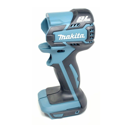
PRODUCT
W
[Drawn above is the image
with BL1830.]
Dimensions: mm (")
Length (L) 147 (5-7/8)
Width (W)
226 (8-7/8)*
Height (H)
244 (9-5/8)*
*
: with Battery BL1815
2
*
: with Battery BL1830
3
)
4
P 1/ 12
L
H
79 (3-1/8)
2
3
Advertisement

Related Manuals for Makita BTD129


Summary of Contents for Makita BTD129
- Page 1 Cordless Impact Driver Model number for North and Central American countries ONCEPT AND MAIN APPLICATIONS Model BTD129 (LXDT08* ) Cordless Impact Driver has been developed specially for light to medium duty fastening applications. This model is equipped with a basic...
- Page 2 P 2/ 12 ariation list BTD129 Plastic Battery Battery Belt Model No. Charger carrying cover clip Type Quantity case BTD129Z BTD129ZK BTD129RFE DC18RC BL1830 BTD129RHE DC18RC BL1815 BTD129SHE DC18SD BL1815 LXDT08* Plastic Battery Battery Belt Model No. Charger carrying cover...
-
Page 3: Necessary Repairing Tools
Retaining ring S and R pliers Removing/ mounting Ring spring 11 of Bit holder section [2] LUBRICATION Apply Makita grease FA No.2 to the following portions indicated by the black triangle to protect parts and product from unusual abrasion. Item No. - Page 4 P 4/ 12 epair [3] DISASSEMBLY/ASSEMBLY [3] -1. Rotor DISASSEMBLING Disassemble Rotor. (Fig. 2) Fig. 2 1. By unscrewing four 4x25 Tapping screws, 2. By unscrewing 8 pcs. of 3x16 Tapping screws, remove Hammer case complete. remove Housing (R). 3x16 Tapping screw Hammer case (8 pcs.) complete...
- Page 5 P 5/ 12 epair [3] DISASSEMBLY/ASSEMBLY [3] -1. Rotor (cont.) ASSEMBLING (1) Assemble Rotor in the reverse order of disassembly. (Refer to Fig. 2) Note: Be careful not to pinch your fingers between Stator and Rotor’s fan when assembling them. (Fig. 4) Fig.
- Page 6 P 6/ 12 epair [3] DISASSEMBLY/ASSEMBLY [3] -2. Anvil and Bit holder section DISASSEMBLING (1) Disassemble Hammer case complete from Housing set. (Refer to Fig. 2) (2) Disassemble Bit holder section. (Figs. 7, 8 and 9) Fig. 7 Fig. 8 Use 1R232 for holding Sleeve firmly Raise this side of Ring spring 11 with index finger to remove it.
- Page 7 P 7/ 12 epair [3] DISASSEMBLY/ASSEMBLY [3] -3. Hammer Section DISASSEMBLING (1) Remove Hammer case complete and Housing (R). (Refer to Fig. 2) (2) Separate Hammer section from Internal gear case complete. (Fig. 10) Fig. 10 Internal gear case complete Hammer section (3) Disassemble Steel balls 5.6.
- Page 8 P 8/ 12 epair [3] DISASSEMBLY/ASSEMBLY [3] -3. Hammer Section (cont.) DISASSEMBLING (4) Now Hammer section is disassembled as drawn in Fig. 12. Fig. 12 2. After removing Flat washer 24, 1. Hammer section can now be disassembled as shown below. Steel balls 3.5 can be removed from Hammer.
-
Page 9: Circuit Diagram
P 9/ 12 ircuit diagram Fig. D-1 Color index of lead wires' sheath Black Yellow White Orange Blue LED Light Printed Switch Stator wiring board Connector Terminal Connector Controller Terminal... -
Page 10: Wiring Diagram
P 10/ 12 iring diagram Fig. D-2 Wiring to Switch Flag connectors of Lead wires must be connected to Switch so that their wires come to Housing (L) side. Switch Flag connectors Lead wires Housing (L) Fig. D-3 Wiring of LED Lead wire Rib C Rib B LED bushing... - Page 11 P 11/ 12 iring diagram Fig. D-4 Wiring in Housing (L) Put the slack portion of Lead wires Printed wiring of Stator and those of Printed wiring board board in this place. Stator Be careful not to put Lead wires on Ribs A, B and D.
- Page 12 P 12/ 12 iring diagram Fig. D-5 Wiring and Mounting of Printed Wiring Board to Stator By fastening four screws, assemble Printed wiring Lead wires of Printed wiring board must be faced board to Insulator without wobbling. to the opposite side of Lead wires of Stator. Note: The screws must be tightened to 0.3N·m of torque.
Need help?
Do you have a question about the BTD129 and is the answer not in the manual?
Questions and answers