Table of Contents
Advertisement
Quick Links
SPECIFICATIONS
Voltage .................................................................................... 24VDC
Current Consumption ............................................................... 8mA*
Power Supply ................................................................. Power Pack
...... B series power packs supply powe for up to 14 CX-105 sensors
.......A series power packs supply power for up to 8 CX-105 sensors
Time Adjustment ........................................ 15 seconds—30 minutes
Sensitivity Adjustment .................................... Minimum—Maximum
*
Current consumption can be slightly higher when only one sensor per power pack is
used.
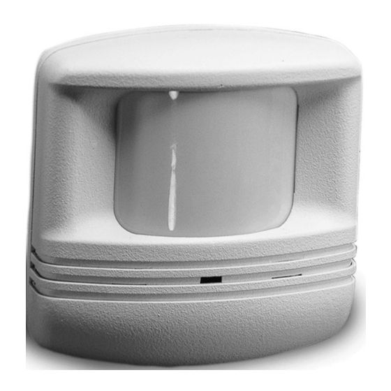
CX-105
PIR Occupancy Sensor
Santa Clara, CA 95050
Advertisement
Table of Contents

Related Manuals for wattstopper CX-105


Summary of Contents for wattstopper CX-105
- Page 1 Current Consumption ............... 8mA* Power Supply ..............Power Pack ..B series power packs supply powe for up to 14 CX-105 sensors ..A series power packs supply power for up to 8 CX-105 sensors Time Adjustment ........15 seconds—30 minutes Sensitivity Adjustment ........
-
Page 2: Unit Description
UNIT DESCRIPTION The CX-105 is a 24VDC passive infrared (PIR) occupancy sensor which controls lighting and HVAC systems based on occupancy. PIR sensing systems are passive systems which react to changes in infrared energy (moving body heat) within the coverage area. PIR sensors must directly “see”... -
Page 3: Installation
INSTALLATION Fig. A The CX-105 sensors can be mounted to walls or ceilings with the supplied swivel bracket, and the supplied junction box cover plate if necessary Half-Circle Notch (see figure C). Mounting at fixture height is most Reference effective. The -3 & -4 sensors can... - Page 4 7. Tighten the Tightening Screw. Industrial Mount Bracket MB-1 In an industrial setting, the MB-1 can be used to mount the CX-105-3 or CX-105-4 to a variety of structures or fixtures, including fluorescent fixtures. MB-1 The MB-1 features an L-shaped bracket and sensor housing.
-
Page 5: Wiring Directions
CAUTION Turn power off at the circuit breaker before installing power packs or sensors. Each WattStopper BZ series power pack can supply power for up to 14 CX-105 sensors. When using more sensors than this, multiple power packs are required. - Page 6 Red (Line) Lighting White POWER PACK Lighting Load Switch Black Red (Load) Wires Control Output 24VDC Control Return +24VDC CX-105 Multiple Sensors and Lighting White (Neutral) Red (Line) White POWER PACK Lighting Load Red (Load) Black Switch Control Output 24VDC (BLU)
-
Page 7: Sensor Adjustment
The Time Delay is set with DIP Switches 1 thru 4. 6 minutes 8 minutes Factory Default: 18 minutes. 10 minutes 12 minutes 14 minutes 16 minutes 18 minutes 20 minutes 22 minutes 24 minutes 26 minutes 28 minutes 30 minutes Override = factory preset www.wattstopper.com... -
Page 8: Troubleshooting
TROUBLESHOOTING CAUTION Turn power off at the circuit breaker before working with or near high voltage. Lights do not turn on with occupancy, and the following condition exists: LED does NOT flash: When power is initially applied to the sensor, there is a warm-up period of up to 60 seconds before the LED is active. - Page 9 3. Adjust the sensor angle (see “Sensor Adjustment”). 4. Relocate the sensor. Override: To override all sensor functions, set DIP switch #5 to on. The red LED will come on and stay on for the duration of the override. www.wattstopper.com...
-
Page 10: Ordering Information
(5) years. There are no obligations or liabilities on the part of WattStopper for consequential damages arising out of, or in connection with, the use or performance of this product or other indirect damages with respect to loss of property, revenue or profit, or cost of removal, installation or reinstallation.
Need help?
Do you have a question about the CX-105 and is the answer not in the manual?
Questions and answers