Advertisement
Table of Contents
This unit is pre-set for Plug n' Go operation,
adjustment is optional.
For full operational details, adjustment and more
features of the product, see the DLM System Installation
Guide provided with the DLM room controllers and also
available at www.wattstopper.com
Installation shall be in accordance with all applicable
regulations, local and NEC codes.
To be connected to a Class 2 power source only.
Class 2 Device Wiring Only – Do Not Reclassify and Install
as Class 1, 3 or Power and Lighting Wiring.
Wire connections shall be rated suitable for the wire
size (lead and building wiring) employed.
Do not apply cleaning solvent directly onto unit. Apply cleaning
solvent onto a cloth, then wipe the unit to clean it.
COVERAGE PATTERN
Do not obstruct the lens.
30'
(9.1m)
20'
(6.1m)
40 ft
35 ft
25 ft
TOP
180°
VIEW
25 ft
35 ft
40 ft
4 ft
SIDE
VIEW
5 ft
25 ft
40 ft
Note: Plus 10° above horizon.
CONNECTIVITY
The illustrations below show examples of free-topology wiring. The LMDW communicates
to all other Digital Lighting Management devices connected to the low voltage DLM Local
Network, regardless of their position on the DLM Local Network.
Corner Mount
Ceiling Mount
Sensor
Sensor
DLM Local Network
LMDW-101
Switch
Switch
Daylight Sensor
BUTTONS AND INDICATORS
Up
Down
On/O
Button
IR Window
PIR
Coverage
Major motion
Minor motion
Ultrasonic
Coverage
Major motion
Minor motion
Line
Voltage
Low Voltage
LMRJ Cables
Line/Hot
Neutral
Black wire
White wire
LMRC
102
Room
Controller
Red wire
to Load A (1)
J-Boxes
LMDW-101
LMDW-102
Voltage ................................................................................ 24VDC
Current Consumption .......................................................... 20mA
Power Supply .............. Watt Stopper/Legrand Room Controllers
Connection to the DLM Local Network ...................2 RJ-45 ports
DLM Local Network Characteristics:
Provides low voltage power over Cat 5e cable (LMRJ).
Supports up to 24 communicating devices, including 4
LMRC-10x or LMPL-101 max per each DLM Local Network.
Free topology up to 1,000ft of low voltage cable.
Environment ................................................. For Indoor Use Only
Operating Temperature ....................32° to 131°F (0° to 55°C)
Storage Temperature ...................... 23° to 176°F (-5° to 80°C)
Relative Humidity ...........................5 to 95% (non condensing)
Patent Pending
Lens release
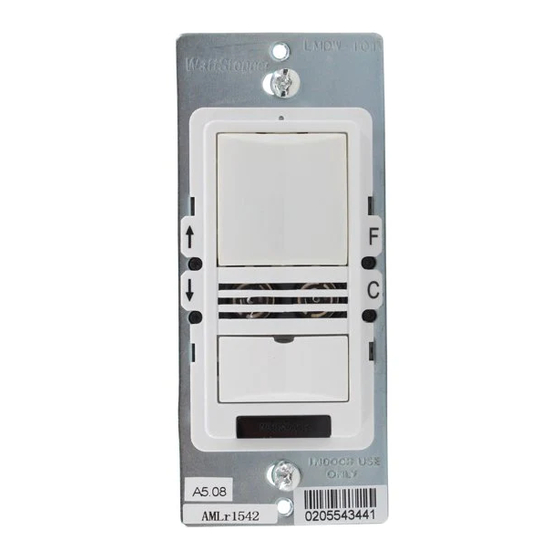
LMDW-101
PIR Lens
Select
Con gure
Button LED
PIR Detection LED
Ultrasonic Detection LED/
Sensor Binding LED
Loads
1
2
Yellow wire
to Load B (2)
LMDW-101/102
Digital Lighting Management
Dual Technology Occupancy Sensor
MOUNTING
WARNING: Do Not Install To Cover a
Junction Box Having Class 1, 3 or Power
and Lighting Circuits.
DLM Local Network
(low voltage, Class 2)
Corner Mount
Occupancy
Sensor
Room
Controller
J Box
To
Load/Line
(Class 1 wiring)
LMDW
Sensor
Switch
LMRJ Cables
Advertisement
Table of Contents

Related Manuals for wattstopper LMDW-101


Summary of Contents for wattstopper LMDW-101
- Page 1 Current Consumption ............20mA Guide provided with the DLM room controllers and also Power Supply ....Watt Stopper/Legrand Room Controllers available at www.wattstopper.com Connection to the DLM Local Network ....2 RJ-45 ports DLM Local Network Characteristics: Installation shall be in accordance with all applicable Provides low voltage power over Cat 5e cable (LMRJ).
- Page 2 Configure the sensor to control the desired lights using the Push n’ Learn adjustment procedure. LEDs turn ON and OFF but load Make sure device is not in PnL. doesn’t switch Check load connections to room controller. 2/2012 Please 2800 De La Cruz Blvd. Phone: 800.879.8585 Recycle Santa Clara, CA 95050 www.wattstopper.com 15006...
Need help?
Do you have a question about the LMDW-101 and is the answer not in the manual?
Questions and answers