Advertisement
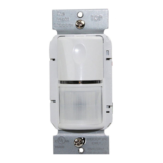
WS-250 & WS-250-347
Passive Infrared Wall Switch
SPECIFICATIONS
WS-250 Voltages ...................................................120 or 277VAC, 60Hz
Load Requirements
@ 120VAC, 60Hz ............. 0-800W ballast & tungsten, 1/6 hp
@ 277VAC, 60Hz ........................................... 0-1200W ballast
WS-250-347 Voltage ........................................................ 347VAC, 60Hz
Load Requirements ............................................. 0-1200W ballast
Time Delay Adjustment ...................................30 seconds - 30 minutes
Sensitivity Adjustment ...........................................Minimum-Maximum
Light Level Adjustment ..................................................... 10 - 200 + FC
Occupancy Sensor
Advertisement
Table of Contents

Related Manuals for wattstopper WS-250


Summary of Contents for wattstopper WS-250
- Page 1 WS-250 & WS-250-347 Passive Infrared Wall Switch Occupancy Sensor SPECIFICATIONS WS-250 Voltages ...........120 or 277VAC, 60Hz Load Requirements @ 120VAC, 60Hz ..... 0-800W ballast & tungsten, 1/6 hp @ 277VAC, 60Hz ........... 0-1200W ballast WS-250-347 Voltage ............347VAC, 60Hz Load Requirements ..........0-1200W ballast Time Delay Adjustment ........30 seconds - 30 minutes...
-
Page 2: Unit Description And Operation
ON and OFF based on occupancy and ambient light level. They are designed to replace a standard light switch. The WS-250 operates with 120 or 277VAC line voltage and the WS-250-347 operates with 347VAC line voltage. All other features are the same in both models. -
Page 3: Coverage Patterns
This allows you to eliminate coverage in unwanted areas. Since masking removes bands of coverage, remember to take this into account when troubleshooting coverage problems. Opaque tape Visit our website for FAQs: www.wattstopper.com... -
Page 4: Installation
INSTALLATION CAUTION Turn the power OFF at the circuit breaker before installing the sensor. Wall Junction Box Wall Switch 1. Connect the existing wires in the wall box to the sensor flying leads. (See Wiring Directions at right). • Do not allow bare wire to show below connector. •... -
Page 5: Wiring Directions
WIRING DIRECTIONS For normal installation of the WS-250 and WS-250-347, connect: 1. LOAD to Red flying lead. 2. LINE to Black flying lead. 3. GROUND to Green . Neutral Load Black to Line Green Single-level wiring Neutral Black to Line... -
Page 6: Sensor Adjustment
The time delay 10 minutes 20 minutes can be set from 30 seconds 5 minutes 25 minutes (see Walk-test feature, light level feature is disabled) to 30 minutes in 5-minute 30 seconds 30 minutes (Walk-test) increments. Visit our website for FAQs: www.wattstopper.com... -
Page 7: Troubleshooting
TROUBLESHOOTING Load will not turn ON: • LED does not fl ash: - Check the sensitivity for proper confi guration. - Check all wire connections. Verify the ground wire is tightly secured. • LED does fl ash: - Press the ON/OFF button. If load does not turn ON, check all wire connections and verify the load wire is tightly secured. -
Page 8: Cover Plates
WattStopper warranties its products to be free of defects in materials and workmanship for a period of five (5) years. There are no obligations or liabilities on the part of WattStopper for consequential damages arising out of, or in connection with, the use or performance of this product or other indirect damages with respect to loss of property, revenue or profit, or cost of removal, installation or reinstallation.
Need help?
Do you have a question about the WS-250 and is the answer not in the manual?
Questions and answers