Cub Cadet 930 SWE Operator's Manual
Hide thumbs
Also See for 930 SWE:
- Operator's manual (35 pages) ,
- Specifications (2 pages) ,
- Operator's manual (32 pages)
Table of Contents
Advertisement
Safe Operation Practices • Set-Up • Operation • Maintenance • Service • Troubleshooting • Warranty
O
'
M
peratOr
s
anual
Two Stage Snow Thrower — Models 930 SWE & 933 SWE
WARNING
READ AND FOLLOW ALL SAFETY RULES AND INSTRUCTIONS IN THIS MANUAL
BEFORE ATTEMPTING TO OPERATE THIS MACHINE.
FAILURE TO COMPLY WITH THESE INSTRUCTIONS MAY RESULT IN PERSONAL INJURY.
CUB CADET LLC, P.O. BOX 361131 CLEVELAND, OHIO 44136-0019
Printed In USA
FORM NO. 769-04977
(06/30/2009)
Advertisement
Table of Contents

Subscribe to Our Youtube Channel
Related Manuals for Cub Cadet 930 SWE


Summary of Contents for Cub Cadet 930 SWE
- Page 1 Safe Operation Practices • Set-Up • Operation • Maintenance • Service • Troubleshooting • Warranty ’ peratOr anual Two Stage Snow Thrower — Models 930 SWE & 933 SWE WARNING READ AND FOLLOW ALL SAFETY RULES AND INSTRUCTIONS IN THIS MANUAL BEFORE ATTEMPTING TO OPERATE THIS MACHINE.
-
Page 2: Table Of Contents
Choose from the options below: ◊ Visit us on the web at www.cubcadet.com ◊ Locate your nearest Cub Cadet Dealer at (877) 282-8684 ◊ Write us at Cub Cadet LLC • P.O. Box 361131 • Cleveland, OH • 44136-0019... -
Page 3: Important Safe Operation Practices
Important Safe Operation Practices WARNING! This symbol points out important safety instructions which, if not followed, could endanger the personal safety and/or property of yourself and others. Read and follow all instructions in this manual before attempting to operate this machine. Failure to comply with these instructions may result in personal injury. - Page 4 Safe Handling of Gasoline Never run an engine indoors or in a poorly ventilated area. Engine exhaust contains carbon monoxide, an odorless To avoid personal injury or property damage use extreme care and deadly gas. in handling gasoline. Gasoline is extremely flammable and the Do not operate machine while under the influence of vapors are explosive.
-
Page 5: Clearing Clogged Discharge Chute
Clearing a Clogged Discharge Chute According to the Consumer Products Safety Commission (CPSC) and the U.S. Environmental Protection Agency (EPA), Hand contact with the rotating impeller inside the discharge this product has an Average Useful Life of seven (7) years, chute is the most common cause of injury associated with snow or 60 hours of operation. -
Page 6: Safety Symbols
Safety Symbols This page depicts and describes safety symbols that may appear on this product. Read, understand, and follow all instructions on the machine before attempting to assemble and operate. Symbol Description READ THE OPERATOR’S MANUAL(S) Read, understand, and follow all instructions in the manual(s) before attempting to assemble and operate WARNING—... -
Page 7: Assembly & Set-Up
Assembly & Set-Up Contents of Carton • One Snow Thrower • Two Replacement Auger Shear Pins • One Chute Assembly • One Snow Thrower Operator’s • One Product Registration Card Manual Assembly Looking beneath the handle panel, check that all of the cables (steering, auger, shift, and drive) are properly routed IMPORTANT: Two replacement auger shear pins are included... - Page 8 Chute Assembly Secure flange keeper removed earlier with lock nuts and screws. Tighten down nuts securing the other two flange Loosen, but do not remove, the chute crank bracket in keepers. See Figure 3-4. order to attached the chute assembly. See Fig. 3-4. Chute Crank Bracket Figure 3-4...
- Page 9 Set-Up Tire Pressure (Pneumatic Tires) The tires can be over-inflated for shipping purposes. Check the Shear Pins tire pressure before operating the snow thrower. Refer to the tire side wall for manufactures’s recommended psi and deflate or A pair of replacement auger shear pins and bow tie cotter pins have been included with your snow thrower.
- Page 10 Adding Fuel Remove the oil filler cap/dipstick. If the level is low, slowly add oil until oil level registers between high (H) and low WARNING! Use extreme care when handling (L), Fig. 3-9. Refer to the Engine Maintenance section for gasoline.
- Page 11 In a well-ventilated area, start the snow thrower engine as instructed in the Operation section of this manual. Make sure the throttle is set in the FAST position. While standing in the operator’s position (behind the snow thrower), engage the auger. Allow the auger to remain engaged for approximately ten (10) seconds before releasing the auger control.
- Page 12 WARNING! Do not over-tighten the cable. Over- Adjusting Drive and Auger Controls tightening may prevent the auger from disengaging From beneath the handle, pull downward on the and compromise the safety of the snow thrower. appropriate cable and unhook the spring found on the end of the cable from its respective actuator bracket.
-
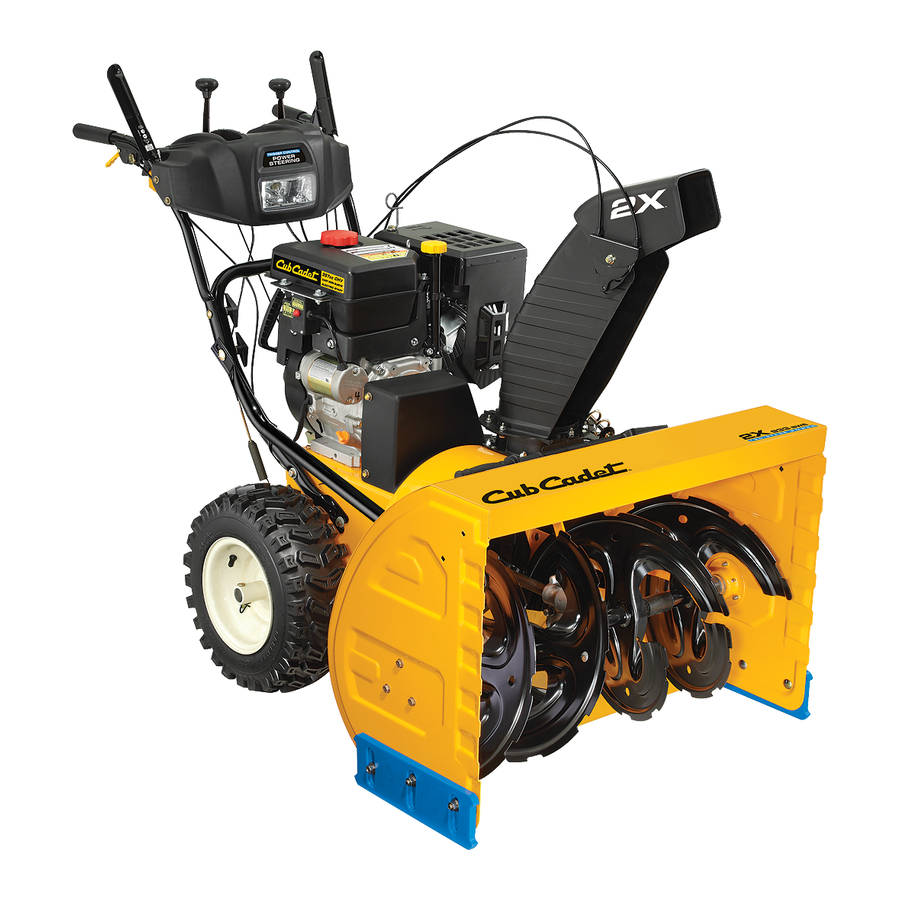
Page 13: Controls And Features
Controls and Features Wheel Drive Control Headlight Speed Selector Lever Two Way Chute Pitch Control™ Fuel Tank Auger Control Fuel Cap Wheel Steering Control Oil Fill Chute Directional Control Chute Assembly Oil Filler Cap/Dipstick Fuel Fill Primer Clean-Out Tool Electric Start Button Electric... - Page 14 Throttle Control Auger Control The throttle control is located on the rear of the engine. It regulates the speed of the engine and will shut off the engine when moved into the STOP position. Primer Pressing the primer forces fuel directly into the engine’s carburetor to aid in starting a “Cold”...
- Page 15 Two-Way Chute-Pitch Control™ Wheel Steering Controls The two-way chute-pitch control is located on the left side of the The left and right wheel steering controls are located on the dash panel and is used to control the distance of snow discharge underside of the handles.
-
Page 16: Operation
Operation Starting The Engine Plug the extension cord into the electric outlet located on the engine. Plug the other end of extension cord into WARNING! Always keep hands and feet clear of a three-prong 120-volt, grounded, AC outlet in a well- moving parts. - Page 17 Recoil Starter To Engage Drive CAUTION! With the throttle control in the Fast (rabbit) position, move Do not pull the starter handle while the shift lever into one of the six forward (F) positions or two engine running. reverse (R) positions. Select a speed appropriate for the snow conditions and a pace you’re comfortable with.
-
Page 18: Operating Tips
Operating Tips Replacing Shear Pins NOTE: Allow the engine to warm up for a few minutes. The Each of the four auger spiral assemblies are secured to the spiral engine will not develop full power until it reaches operating shaft with a shear pin and cotter pin. If the auger should strike a temperature. -
Page 19: Maintenance & Adjustment
Maintenance & Adjustments Maintenance Slide the shave plate out of the off-set slot at the bottom of the housing, and from between the skid shoes and side WARNING! Before servicing, repairing, lubricating, panels of the housing. or inspecting, disengage all controls and stop With the mounting holes facing toward the back of the engine. - Page 20 Auger Shaft At least once a season, one at a time, remove the shear pins from the auger shaft. Spray lubricant inside the hub of each auger spiral assembly and around the spacers on the auger shaft. See Figure 6-3. Grease fittings can also be found at each end of the auger shaft.
- Page 21 Drive Control If there is no friction wheel clearance when the drive control is disengaged, or the friction wheel does not solidly ” Refer to “Auger and Drive Control Cables of the Assembly & Set-Up - contact the drive friction plate when the drive control is Section 3 for instructions to adjust the drive control.
-
Page 22: Engine Maintenance
Engine Maintenance WARNING! Periodic inspection and adjustment of the engine is essential if To prevent accidental start-up, shut off high level performance is to be maintained. Regular maintenance the engine and remove the key before performing will also ensure a long service life. The required service intervals any type of engine maintenance. -
Page 23: Spark Plug
Spark Plug Check that the spark plug washer is in good condition and thread the spark plug in by hand to prevent cross- WARNING! DO NOT check for spark with spark threading. plug removed. DO NOT crank engine with spark After the spark plug is seated, tighten with a spark plug plug removed. -
Page 24: Service
Service Belt Replacement Belt Removal Preparation Remove Remove the chute crank assembly bracket by removing the nuts and washers shown in Fig. 8-1. Loosen Nuts & Washers Figure 8-3 Auger Belt Replacement To remove and replace your snow thrower’s auger belt, proceed as follows: Remove the bow tie clip and flat washer from the ferrule in order to disconnect the auger idler rod from... - Page 25 Pull the brake bracket assembly towards the cable guide Lift the brake bracket assembly out of the pulley groove roller and unhook the auger cable “Z” fitting. Refer to and slide the pulley assembly off the posts of the auger Fig.
- Page 26 Make sure to remove the piece of wood blocking the Drain the gasoline from the snow thrower. NOTE: impeller. Tip the snow thrower up and forward, so that it rests on the housing. Check the auger drive belt adjustment. With the auger clutch lever in the disengaged position, the top surface of Remove screws from the frame cover underneath the the new belt should be even with the outside diameter of...
- Page 27 Lift the friction wheel assembly out between the axle Slide the hex shaft through the right side of the frame shaft and the drive shaft assemblies. toward the left side and through the friction wheel assembly. Remove four screws securing the friction wheel to the hub assembly (refer to Fig.
- Page 28 Off-Season Storage Long-Term Storage Engines stored over 30 days need to be drained of fuel If the snow thrower will not be used for 30 days or longer, to prevent deterioration and gum from forming in fuel the equipment needs to be stored properly. Follow storage system or on essential carburetor parts.
-
Page 29: Troubleshooting
Troubleshooting Problem Cause Remedy Engine fails to start Choke not in CHOKE position. Move choke to CHOKE position. Spark plug wire disconnected. Connect wire to spark plug. Fuel tank empty or stale fuel. Fill tank with clean, fresh gasoline. Engine not primed. Prime engine as instructed in “Operating Your Snow Thrower”. -
Page 30: Replacement Parts
Replacement Parts Component Part Number and Description 929-0071 Extension Cord, 110V 954-04194A Auger Drive Belt 954-04202 Wheel Drive Belt 918-04178 Friction Wheel Assembly 718-04034 Friction Wheel w/Bonded Rubber 725-1629 Lamp 738-04155 Shear Pin 714-04040 Bow-tie Cotter Pin 731-07032 Slide Shoe, Deluxe 731-2643 Chute Clean-out Tool 790-00195A... - Page 31 Notes...
- Page 32 11— n ectiOn Otes...
- Page 33 10 — n ectiOn Otes...
- Page 34 MTD CONSUMER GROUP INC (MTD), the California Air Resources Board (CARB) and the United States Environment Protection Agency (U. S. EPA) Emission Control System Warranty Statement (Owner’s Defect Warranty Rights and Obligations) EMISSION CONTROL SYSTEM COVERAGE IS APPLICABLE TO CERTIFIED ENGINES PURCHASED IN CALIFORNIA IN 2005 AND THERE- AFTER, WHICH ARE USED IN CALIFORNIA, AND TO CERTIFIED MODEL YEAR 2005 AND LATER ENGINES WHICH ARE PURCHASED AND USED ELSEWHERE IN THE UNITED STATES.
- Page 35 (4) Repair or replacement of any warranted part under the warranty provisions of this article must be performed at no charge to the owner at a warranty station. (5) Notwithstanding the provisions of Subsection (4) above, warranty services or repairs must be provided at all MTD distribution centers that are franchised to service the subject engines.
- Page 36 MANUFACTURER’S LIMITED WARRANTY FOR SNOW THROWERS The limited warranty set forth below is given by Cub Cadet LLC with b. Cub Cadet does not extend any warranty for products sold or respect to new merchandise purchased and used in the United States,...
Need help?
Do you have a question about the 930 SWE and is the answer not in the manual?
Questions and answers