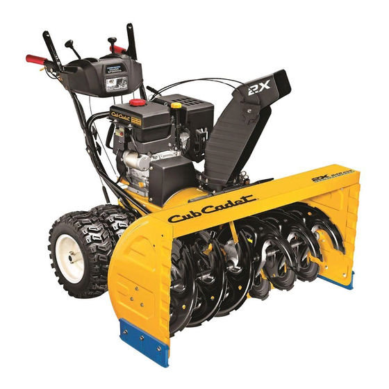
Cub Cadet 945 SWE Operator's Manual
Two stage snow thrower
Hide thumbs
Also See for 945 SWE:
- Operator's manual (32 pages) ,
- Specifications (2 pages) ,
- Operator's manual (28 pages)
Table of Contents
Advertisement
Safe Operation Practices • Set-Up • Operation • Maintenance • Service • Troubleshooting • Warranty
O
'
M
peratOr
s
anual
Two Stage Snow Thrower — Model 945 SWE
WARNING
READ AND FOLLOW ALL SAFETY RULES AND INSTRUCTIONS IN THIS MANUAL
BEFORE ATTEMPTING TO OPERATE THIS MACHINE.
FAILURE TO COMPLY WITH THESE INSTRUCTIONS MAY RESULT IN PERSONAL INJURY.
CUB CADET LLC, P.O. BOX 361131 CLEVELAND, OHIO 44136-0019
Printed In USA
FORM NO. 769-09711
(March 26, 2014)
Advertisement
Table of Contents

Related Manuals for Cub Cadet 945 SWE


Summary of Contents for Cub Cadet 945 SWE
- Page 1 Safe Operation Practices • Set-Up • Operation • Maintenance • Service • Troubleshooting • Warranty ’ peratOr anual Two Stage Snow Thrower — Model 945 SWE WARNING READ AND FOLLOW ALL SAFETY RULES AND INSTRUCTIONS IN THIS MANUAL BEFORE ATTEMPTING TO OPERATE THIS MACHINE.
-
Page 2: Table Of Contents
Visit us on the web at www.cubcadet.com See How-to Maintenance and Parts Installation Videos at www.cubcadet.com/tutorials ◊ Locate your nearest Cub Cadet Dealer at (877) 282-8684 ◊ Write us at Cub Cadet LLC • P.O. Box 361131 • Cleveland, OH • 44136-0019... -
Page 3: Important Safe Operation Practices
Important Safe Operation Practices WARNING! This symbol points out important safety instructions which, if not followed, could endanger the personal safety and/or property of yourself and others. Read and follow all instructions in this manual before attempting to operate this machine. Failure to comply with these instructions may result in personal injury. - Page 4 Safe Handling of Gasoline Never run an engine indoors or in a poorly ventilated area. Engine exhaust contains carbon monoxide, an odorless To avoid personal injury or property damage use extreme care and deadly gas. in handling gasoline. Gasoline is extremely flammable and the Do not operate machine while under the influence of vapors are explosive.
-
Page 5: Maintenance & Storage
Clearing a Clogged Discharge Chute According to the Consumer Products Safety Commission (CPSC) and the U.S. Environmental Protection Agency (EPA), Hand contact with the rotating impeller inside the discharge this product has an Average Useful Life of seven (7) years, chute is the most common cause of injury associated with snow or 60 hours of operation. - Page 6 Safety Symbols This page depicts and describes safety symbols that may appear on this product. Read, understand, and follow all instructions on the machine before attempting to assemble and operate. Symbol Description READ THE OPERATOR’S MANUAL(S) Read, understand, and follow all instructions in the manual(s) before attempting to assemble and operate WARNING—...
-
Page 7: Assembly & Set-Up
Assembly & Set-Up Contents of Carton • One Snow Thrower • One Engine Operator’s Manual • One Chute Assembly • One Snow Thrower Operator’s • Two Replacement Auger Shear Pins • One Product Registration Card Manual Assembly IMPORTANT: Two replacement auger shear pins are included with this manual (or stowed in the plastic handle panel). - Page 8 Chute Directional Control Secure flange keeper removed earlier with lock nuts and screws. Tighten down nuts securing the other two flange Remove the hairpin clip from the spiral control as shown in keepers. See Figure 3-5. A of Figure 3-4. Check that the chute cables are properly routed through Insert the chute directional control rod into the fitting on the cable guide attached to the lower handle assembly.
-
Page 9: Skid Shoes
Chute Clean-Out Tool CAUTION: Operating a snow thrower equipped with steel skid shoes may result in damage to The chute clean-out tool is fastened to the top of the auger natural stone paver surfaces (e.g. sandstone, housing with a mounting clip and a cable tie at the factory. Cut bluestone, limestone). - Page 10 Shift Lever Chute Tilt Control Auger Drive Control Control Auger Drive Control Control Cable Cable Rearward most hole of the actuator brackets Figure 3-10 Figure 3-11 With the auger control in the disengaged “up” position, walk to the front of the machine. Confirm that the auger has completely stopped rotating and shows NO signs of motion.
-
Page 11: Controls And Features
Controls and Features Two-way Chute Control™ Drive Control Speed Selector Shift Lever Auger Control Headlight Heated Hand Grip Chute Assembly Wheel Steering Control Chute Clean-out Tool Directional Control Auger Auger Housing Skid Shoe Skid Shoes NOTE: For detailed information on all engine controls, refer to the separate Engine Operator’s Manual supplied with this unit. -
Page 12: Auger Control
Auger Control Two-Way Chute Control™ The auger control is located on the left handle. Squeeze the The two-way chute control is located on the left side of the dash control grip against the handle to engage the augers and start panel and is used to control the distance of snow discharge from snow throwing action. - Page 13 Chute Directional Control The chute directional control is located on the left side of the snow thrower. • To change the direction in which snow is thrown, crank clockwise to discharge to the left and counterclockwise to discharge to the right. Wheel Steering Controls The left and right wheel steering controls are located on the underside of the handles.
-
Page 14: Operation
Operation Starting and Stopping the Engine Replacing Shear Pins Each of the auger spiral assemblies are secured to the spiral shaft Refer to the Engine Operator’s Manual packed with your snow with a shear pin and bow-tie cotter pin. If the auger should strike thrower for instructions on starting and stopping the engine. -
Page 15: Maintenance & Adjustment
Maintenance & Adjustments WARNING! Wheels Before performing any type of maintenance/service, disengage all controls and stop At least once a season, remove both wheels. Clean and coat the the engine. Wait until all moving parts have come to a axles with a multipurpose automotive grease before reinstalling complete stop. - Page 16 Shave Plate and Skid Shoes Pivot the bracket downward to take up slack in the cable. Retighten the hex nut. The shave plate and skid shoes on the bottom of the snow thrower are subject to wear. They should be checked periodically and replaced when necessary.
- Page 17 Wheel drive control If there is no friction wheel clearance, or the friction wheel does not solidly contact the drive plate, re-adjust the Refer to the Adjustment section of the Assembly & Set-Up lock nut on the lower end of the drive cable following the section earlier in this manual for instructions on how to adjust instructions in the Assembly section.
-
Page 18: Service
Service Belt Replacement Loosen the bolt shown in Figure 7-3 securing the belt keeper bracket and remove the other bolt. Push the belt Belt Removal Preparation keeper bracket up off the engine pulley. Refer to Figure 7-3. Disconnect the chute crank assembly at the discharge chute end by removing the hairpin clip and the flat washer. - Page 19 Slip the auger control belt (the front belt) off the engine Block the impeller with a piece of wood the prevent from pulley. spinning and use a 1/2” wrench to remove the hex screw and flat washer from the center of the auger input shaft Pull the brake bracket assembly towards the cable guide and auger pulley adapter.
- Page 20 If also replacing the drive belt, proceed to the “Drive Belt” Install the new belt on the pulleys in the reverse order and re- instruction. If not, reposition the transmission frame back tension with the idler pulley. onto the auger housing. Install the drive belt on the engine Reassemble by performing the previous steps in the pulley, re-connect the auger cable “Z”...
- Page 21 Holding the friction wheel assembly, slide the hex shaft out Reposition the friction wheel assembly in the snow thrower of the right side of the frame. The spacer on the left side frame. Insert the pin from the shift arm assembly into the of the hex shaft will fall and the sprocket should remain friction wheel assembly and hold assembly in position.
-
Page 22: Troubleshooting
Troubleshooting Problem Cause Remedy Excessive vibration 1. Loose parts or damaged auger. 1. Stop engine immediately and disconnect spark plug wire. Tighten all bolts and nuts. If vibration continues, have unit serviced by an authorized service center. Loss of power 1. -
Page 23: Replacement Parts
Replacement Parts Component Part Number and Description 929-0071A Extension Cord, 110V 954-04194A Auger Drive Belt 954-04202 Wheel Drive Belt 918-04178 Friction Wheel Assembly 718-04034 Friction Wheel w/Bonded Rubber 725-05326 Lamp 738-04155 Shear Pin 714-04040 Bow-tie Cotter Pin 731-07032 Slide Shoe, Deluxe 931-2643 Chute Clean-out Tool 790-00280... -
Page 24: Attachments & Accessories
Attachments & Accessories The following attachments and accessories are available for your Cub Cadet 945 series snow thrower. See your Cub Cadet dealer or the retailer from which you purchased your snow thrower for information regarding price and availability. Model Number... - Page 25 Notes...
-
Page 28: Warranty
No implied warranty, including any implied warranty of “Cub Cadet” will, at its option, repair or replace, free of charge, any merchantability of fitness for a particular purpose, applies part found to be defective in materials or workmanship. This limited...
Need help?
Do you have a question about the 945 SWE and is the answer not in the manual?
Questions and answers