Cub Cadet 930 SWE Operator's Manual
Two stage snow thrower
Hide thumbs
Also See for 930 SWE:
- Operator's manual (36 pages) ,
- Specifications (2 pages) ,
- Operator's manual (28 pages)
Table of Contents
Advertisement
Safety • Assembly • Operation • Tips & Techniques • Maintenance • Troubleshooting • Parts Lists • Warranty
OPERATOR'S MANUAL
Two Stage Snow Thrower — Models 930 SWE & 933 SWE
READ SAFETY RULES AND INSTRUCTIONS CAREFULLY BEFORE OPERATION
Warning: This unit is equipped with an internal combustion engine and should not be used on or near any uniiproved forest-covered, brush-
covered or grass-covered land unless the engine's exhaust system is equipped with a spark arrester meeting applicable local or state laws (if any).
If a spark arrester is used, it should be maintained in effective working order by the operator. In the State of California the above is required by law
(Section 4442 of the California Public Resources Code). Other states may have similar laws. Federal laws apply on federal lands. A spark arrester
for the muffler is available through your nearest engine authorized service dealer or contact the service department, P.O. Box 361131 Cleveland,
Ohio 44136-0019.
PRINTED IN U.S.A
31AE9PSV710
31AE9LSU710
31AE9LSU756
CUB CADET LLC, P.O. BOX 361131 CLEVELAND, OHIO 44136-0019
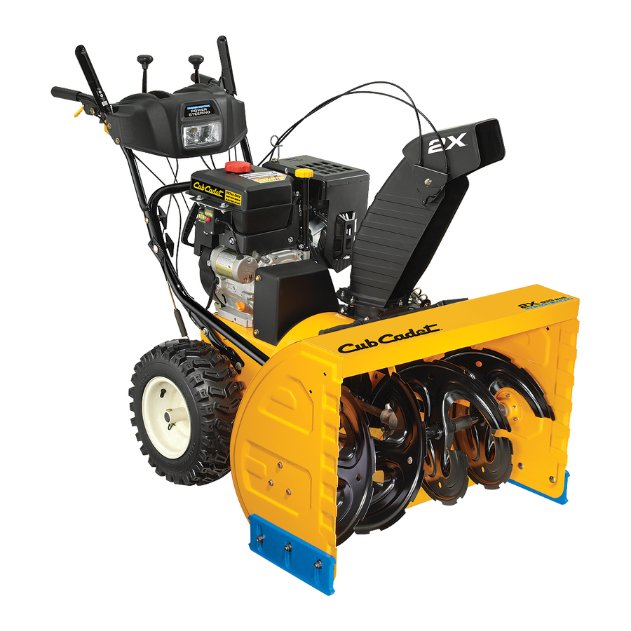
Model 31AE9PSV710 shown
IMPORTANT
FORM NO. 769-02572
6/28/06
Advertisement
Table of Contents

Related Manuals for Cub Cadet 930 SWE


Summary of Contents for Cub Cadet 930 SWE
- Page 1 31AE9LSU710 31AE9LSU756 Two Stage Snow Thrower — Models 930 SWE & 933 SWE READ SAFETY RULES AND INSTRUCTIONS CAREFULLY BEFORE OPERATION Warning: This unit is equipped with an internal combustion engine and should not be used on or near any uniiproved forest-covered, brush- covered or grass-covered land unless the engine’s exhaust system is equipped with a spark arrester meeting applicable local or state laws (if any).
-
Page 2: Table Of Contents
1. Visit cubcadet.com for many useful suggestions. Click on Customer Service or the Service Locator to find the nearest Cub Cadet service dealer in your area. 2. To reach the Customer Dealer Referral Line, please call 1-877-282-8684. -
Page 3: Safety Labels
A chute clean-out tool is fastened to the top of the auger housing with a mounting clip. The tool is designed to clear a chute assembly of ice and snow. This item is fastened with a cable tie at the factory. Cut the cable tie before operating the snow thrower. -
Page 4: Safe Operation Practices
DANGER: This machine was built to be operated according to the rules for safe operation in this manual. As with any type of power equipment, carelessness or error on the part of the operator can Safe result in serious injury. This machine is capable of amputating hands and feet and throwing objects. Failure to observe the following safety instructions could result in serious injury or death. -
Page 5: Maintenance And Storage
Operation 1. Do not put hands or feet near rotating parts, in the auger/impeller housing or chute assembly. Contact with the rotating parts can amputate hands and feet. 2. The auger/impeller control lever is a safety device. Never bypass its operation. Doing so makes the machine unsafe and may cause personal injury. -
Page 6: Setting Up Your Snow Thrower
Setting Up Your Snow Thrower NOTE: All references in this manual to the left or right side of the snow thrower is from the operating position only. Exceptions, if any, will be specified. IMPORTANT This unit is shipped with the engine full of oil. - Page 7 3. a. Remove the flat washer and hairpin clip from the end of the chute directional control. See Figure 3-3. b. Insert the end of the chute directional control into the chute bracket and secure with the flat washer and hairpin clip just removed. If necessary, the chute bracket can be adjusted.
-
Page 8: Auger Drive
Setting Up Your Snow Thrower Specifications are Auger subject to change without notification or obligation. Control Images may not reflect Cable your exact model and are for reference purposes only. Make these final assembly adjustments before operating your snow thrower for the first time. Failure to follow these instructions may cause damage to the snow thrower. - Page 9 Adjusting Drive and Auger Controls 1. From beneath the handle, pull downward on the appropriate cable and unhook the spring found on the end of the cable from its respective actuator bracket. Refer to Figures 3-8 and 3-9. 2. Slide the spring up the cable to expose the cable coupler threads and lock nut.
-
Page 10: Operating Your Snow Thrower
Operating Your Snow Thrower WARNING Read, understand, and follow all instruc- tions and warnings on the machine and in this manual before 33-inch model shown operating. Now that you have setup your snow thrower, it’s important to become acquainted with its controls and features. NOTE: For detailed starting instructions and more information on all engine controls, refer to the Tecumseh Engines manual packed separately and... -
Page 11: Auger Control
Auger Control The auger control is located on the left handle. Squeeze the control grip against the handle to engage the augers and start snow throwing action. Release to stop. Drive Control / Auger Lock The drive control is located on the right handle. Squeeze the control grip against the handle to engage the wheel drive. -
Page 12: Starting The Engine
Gas & Oil Fill-Up Service the engine with gasoline and oil as instructed in the Tecumseh Engines manual packed separately with your snow thrower. Read instructions carefully. Operating Your Snow Thrower or while the engine is hot or running. Extinguish cigarettes, cigars, pipes and other sources of ignition. -
Page 13: Stopping The Engine
Stopping The Engine Run engine for a few minutes before stopping to help dry off any moisture on the engine. 1. Move throttle control to STOP position. 2. Remove the ignition key (Do not turn key) to prevent unauthorized use of equipment. 3. -
Page 14: Specifications Are Subject To Change Without Notification Or Obligation. Images May Not Reflect Your Exact Model And Are For Reference Purposes Only
Making Adjustments WARNING Read, understand, and follow all instructions and warnings on the machine and in this manual before operat- ing. Never attempt to make any adjustments while the engine is running, except where specified in operator’s manual. Specifications are subject to change without notification or obligation. -
Page 15: Skid Shoes
Skid Shoes The space between this shave plate and the ground can be adjusted. For close snow removal, place skid shoes in the low position. Use middle or high position when area to be cleared is uneven. 1. Adjust skid shoes by loosening the six hex nuts, washers, and carriage bolts and moving skid shoes to desired position. -
Page 16: Maintaining Your Snow Thrower
Maintaining Your Snow Thrower WARNING Always stop engine, disconnect spark Refer to the separate Tecumseh Engines manual packed with your unit for all engine maintenance. plug, and ground against engine before performing any type of maintenance on Engine your machine. Refer to the Tecumseh Engines manual packed with your unit for all engine lubrication instructions. -
Page 17: Shave Plate
Shave Plate and Skid Shoes The shave plate and skid shoes on the bottom of the snow thrower are subject to wear. Check these periodi- cally and replace as necessary. Skid Shoes NOTE: The skid shoes on this machine have two wear edges. - Page 18 Maintaining Your Snow Loosen Thrower WARNING Always stop engine, disconnect spark plug, and ground against engine before performing any type of maintenance on your machine. 6. Slip the auger control belt (the front belt) off the engine pulley. Remove 7. Pull the brake bracket assembly towards the cable guide roller and unhook the auger cable “Z”...
-
Page 19: Drive Belt
If also replacing the drive belt, proceed to the “Drive Belt” instruction. If not, reassemble by performing the previous steps in the opposite order and manner of removal. Proper Adjustment: With the auger clutch lever in the disengaged position, the top surface of the new belt should be even with the outside diameter of the pulley. -
Page 20: Changing Friction Wheel
Maintaining Your Snow Thrower WARNING Always stop engine, disconnect spark plug, and ground against engine before performing any type of maintenance on your machine. Figure 6-13 Remove hex screw and washer Hex Shaft Figure 6-14 Changing Friction Wheel The rubber on the friction wheel is subject to wear and should be checked after the first 25 hours of operation, and periodically thereafter. - Page 21 • Reassemble the new friction wheel to the hub assembly, tightening the four screws in rotation and with equal force. It is important to assemble the friction wheel symmetrically for proper functioning. • Insert the pin from the shift arm assembly into the friction wheel assembly and hold assembly in position.
-
Page 22: Off-Season Storage
If the snow thrower will not be used for 30 days or longer, or if it is the end of the snow season when the last pos- sibility of snow is gone, the equipment needs to be stored properly. Follow storage instructions below to ensure top performance from the snow thrower for many more years. - Page 23 Problem Engine fails to start 1. Choke not in ON position. 2. Spark plug wire disconnected. 3. Fuel tank empty or stale fuel. 4. Engine not primed. 5. Faulty spark plug. 6. Blocked fuel line. 7. Safety key not in ignition on engine. Engine runs erratic 1.
- Page 24 Models 930 SWE & 933 SWE...
-
Page 25: Parts List
Ref. No. Part No. Description 05244B Housing, Bearing 784-0315A Housing, Double D Bearing 618-0436 Gear Box Assembly, Auger 618-0281A Bracket Assy, Auger Brake 684-0090B Impellar, 16” 684-04232 Housing, Auger - 30” 684-04233 Housing, Auger - 33” 684-04151 Spiral Assy, LH 684-04152 Spiral Assy, RH 710-0371... - Page 26 Models 930 SWE & 933 SWE...
- Page 27 Ref. No. Part No. Description 684-04106B Handle Engage Assy - RH 731-0851A Chute, Flange Keeper 731-04894B Lock Plate 711-04287 Pivot Rod 735-0199A Rubber Bumper 710-04354 Screw, 1/4-20 x.375 731-04896A Clutch Lock Cam 712-04081A Shoulder Nut, 1/4-20 725-04214 Wire Harness 725-1649 Light Socket 720-0274 Handle Grip...
- Page 28 Models 930 SWE & 933 SWE...
- Page 29 Ref. No. Part No. Description 05244B Housing, Bearing 618-0279 Dogg, Steering Drive, LH 618-0280 Dogg, Steering Drive, RH 618-0282E Shaft Assembly, Steering 618-04178 Assembly, Friction Wheel 718-04034 Wheel, Friction, Bonded 710-0896 Screw, Hex Wash 684-0118A Bracket, Auger Actuator 684-0119A Bracket, Drive Actuator 684-04235 Sprocket, 32T 790-00218A...
- Page 30 Models 930 SWE & 933 SWE Parts List Continued from previous page Ref. No. Part No. Description 710-1245B Screw, Hx Cap 5/16-24 710-0654A Screw, 3/8-16 x 1.00 736-0173** Washer, Flat, .28 x .74 x .063 714-0118 Key, Square, 1/4 x 1.5...
-
Page 31: Warranty
MANUFACTURER’S LIMITED COMMERCIAL WARRANTY FOR: The limited warranty set forth below is given by Cub Cadet LLC with re- spect to new merchandise used for commercial purposes and purchased and used in the United States and/or its territories and possessions, and... - Page 32 MANUFACTURER’S LIMITED WARRANTY FOR The limited warranty set forth below is given by Cub Cadet LLC with respect to new merchandise purchased and used in the United States, its possessions and territories, and by MTD Products Limited with respect to new merchandise purchased and used in Canada and/or its territories and possessions.
Need help?
Do you have a question about the 930 SWE and is the answer not in the manual?
Questions and answers