Cub Cadet 930 SWE Operator's Manual
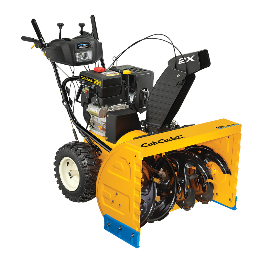
Two stage snow thrower
Hide thumbs
Also See for 930 SWE:
- Operator's manual (36 pages) ,
- Specifications (2 pages) ,
- Operator's manual (28 pages)
Table of Contents
Advertisement
Safe Operation Practices • Set-Up • Operation • Maintenance • Service • Troubleshooting • Warranty
O
'
M
peratOr
s
anual
Two Stage Snow Thrower — Models 930 SWE & 933 SWE
WARNING
READ AND FOLLOW ALL SAFETY RULES AND INSTRUCTIONS IN THIS MANUAL
BEFORE ATTEMPTING TO OPERATE THIS MACHINE.
FAILURE TO COMPLY WITH THESE INSTRUCTIONS MAY RESULT IN PERSONAL INJURY.
CUB CADET LLC, P.O. BOX 361131 CLEVELAND, OHIO 44136-0019
Printed In USA
FORM NO. 769-02572A
(July, 2007)
Advertisement
Table of Contents

Related Manuals for Cub Cadet 930 SWE


Summary of Contents for Cub Cadet 930 SWE
- Page 1 Safe Operation Practices • Set-Up • Operation • Maintenance • Service • Troubleshooting • Warranty ’ peratOr anual Two Stage Snow Thrower — Models 930 SWE & 933 SWE WARNING READ AND FOLLOW ALL SAFETY RULES AND INSTRUCTIONS IN THIS MANUAL BEFORE ATTEMPTING TO OPERATE THIS MACHINE.
-
Page 2: Table Of Contents
To The Owner Thank You Thank you for purchasing a Snow Thrower manufactured by Cub Cadet LLC. It was carefully engineered to provide excellent performance when properly operated and maintained. Please read this entire manual prior to operating the equipment. It instructs you how to safely and easily set up, operate and maintain your machine. -
Page 3: Important Safe Operation Practices
Important Safe Operation Practices WARNING! This symbol points out important safety instructions which, if not followed, could endanger the personal safety and/or property of yourself and others. Read and follow all instructions in this manual before attempting to operate this machine. Failure to comply with these instructions may result in personal injury. - Page 4 Safe Handling of Gasoline To avoid personal injury or property damage use extreme care in handling gasoline. Gasoline is extremely flammable and the vapors are explosive. Serious personal injury can occur when gasoline is spilled on yourself or your clothes which can ignite. Wash your skin and change clothes immediately.
-
Page 5: Maintenance & Storage
Maintenance & Storage Never tamper with safety devices. Check their proper operation regularly. Refer to the maintenance and adjustment sections of this manual. Before cleaning, repairing, or inspecting machine disengage all control levers and stop the engine. Wait until the auger/impeller come to a complete stop. Disconnect the spark plug wire and ground against the engine to prevent unintended starting. -
Page 6: Assembly & Set-Up
Assembly & Set-Up Contents of Carton • One Snow Thrower • One Snow Thrower Operator’s Manual Assembly IMPORTANT: Two replacement auger shear pins are included with this manual (or stowed in the plastic handle panel). Refer to the Maintenance section for more informa- tion regarding shear pin replacement. -
Page 7: Chute Clean-Out Tool
Place chute assembly onto chute base as shown in Figure 3-4. Make sure that the chute notches engage with the spiral end of chute directional control, and the two flange keepers are beneath the flange on the chute base. Figure 3-4 Secure flange keeper removed earlier with lock nuts and screws. -
Page 8: Skid Shoes
Tire Pressure (Pneumatic Tires) The tires are over-inflated for shipping purposes. Check the tire pressure before operating the snow thrower. Refer to the tire side wall for tire manufacturer’s recommended psi and deflate (or inflate) the tires as necessary. NOTE: If the tire pressure is not equal in both tires, the unit may pull to one side or the other and the shave plate will not sit level on the ground IMPORTANT: Under any circumstance do not exceed... - Page 9 Allow the auger to remain engaged for approximately ten (10) seconds before releasing the auger control. Repeat this several times. With the throttle control in the FAST (rabbit) position and the auger control in the disengaged “up” position, walk to the front of the machine. Confirm that the auger has completely stopped rotating and shows NO signs of motion.
-
Page 10: Controls And Features
Controls and Features Gas Cap Oil Fill Chute Assembly Augers Snow thrower controls and features are described below and illustrated in Fig. 4-1. NOTE: For detailed information on all engine controls, refer to the separate Tecumseh Engine Operator’s Manual. Shift Lever The shift lever is located in the right side of the handle panel and is used to determine ground speed and direction of travel. -
Page 11: Throttle Control
Throttle Control The throttle control is located on the rear of the engine. It regulates the speed of the engine and will shut off the engine when moved into the STOP position. Primer Bulb Pressing the primer bulb forces fuel directly into the engine’s carburetor to aid in starting a “Cold”... - Page 12 Two-Way Chute Control™ The two-way chute control is located on the left side of the dash panel and is used to control the distance of snow discharge from the chute. • To change the upper chute angle to control the distance that snow is thrown, pivot the lever forward or backward.
-
Page 13: Operation
Operation Starting The Engine Attach spark plug wire to spark plug. Make certain the metal loop on the end of the spark plug wire (inside the rubber boot) is fastened securely over the metal tip on the spark plug. Make certain both the auger control and drive control are in the disengaged (released) position. -
Page 14: Operating Tips
To Engage Drive With the throttle control in the Fast (rabbit) position, move shift lever into one of the six forward (F) positions or two reverse (R) positions. Select a speed appropriate for the snow conditions and a pace you’re comfortable with. NOTE: Use slower speeds in higher snow and/or until you are familiar with the snow thrower operation Squeeze the drive control against the handle the... -
Page 15: Maintenance & Adjustment
Maintenance & Adjustments Maintenance Engine Refer to the Tecumseh Engine manual packed with your machine for all engine maintenance. Shave Plate and Skid Shoes The shave plate and skid shoes on the bottom of the snow thrower are subject to wear. They should be checked periodically and replaced when necessary. -
Page 16: Shear Pin
Auger Shaft At least once a season, one at a time, remove the shear pins from the auger shaft. Spray lubricant inside the hub of each auger spiral assembly and around the spacers on the auger shaft. See Figure 6-3. Grease fittings can also be found at each end of the auger shaft. - Page 17 Drive Control ” Refer to “Auger and Drive Control Cables of the Assembly & Set- Up - Section 3 for instructions to adjust the drive control. To further check the adjustment, proceed as follows: With the snow thrower tipped forward (be certain to drain gasoline or place plastic film under the gas cap if the snow thrower has already been operated), remove the frame cover underneath the snow...
-
Page 18: Service
Service Belt Replacement Belt Removal Preparation Disconnect the chute crank assembly at the discharge chute end by removing the hairpin clip and the flat washer. Refer to Figure 7-1. Figure 7-1 Remove the plastic belt cover on the front of the engine by removing the three self-tapping screws. - Page 19 Figure 7-5 From both sides of the frame assembly, use a 1/2" wrench to remove the three hex tap screws securing the transmission frame to the auger housing assembly. Refer to Figure 7-1. NOTE: Do not remove the lower hex flange lock nut on each side.
-
Page 20: Changing Friction Wheel
To adjust, disconnect ferrule from brake bracket assembly. Thread ferrule in (towards idler) to increase tension on belt, or out to decrease belt tension. The brake puck must always be firmly seated in the NOTE: pulley groove when auger control is disengaged. Repeat the “Testing Auger Drive Control”... -
Page 21: Off-Season Storage
Figure 7-11 Reposition the friction wheel assembly in the snow thrower frame. Insert the pin from the shift arm assembly into the friction wheel assembly and hold assembly in position. Refer to Figure 7-12. Figure 7-12 Slide the hex shaft through the right side of the frame toward the left side and through the friction wheel assembly. -
Page 22: Troubleshooting
Troubleshooting Problem Engine fails to start Engine runs erratic Engine overheats Excessive vibration Loss of power Unit fails to propel itself Unit fails to discharge snow Cause Choke control not in ON position. Spark plug wire disconnected. Fuel tank empty or stale fuel. Engine not primed. -
Page 23: Replacement Parts
Replacement Parts Component Friction Wheel w/Bonded Rubber Phone (800) 965-4 (4282) to order replacement parts or a complete Parts Manual (have your full model number and serial number ready). Parts Manual downloads are also available free of charge at www.cubcadet.com. Description Extention Cord, 110V Auger Drive Belt... - Page 24 MANUFACTURER’S LIMITED WARRANTY FOR The limited warranty set forth below is given by Cub Cadet LLC with respect to new merchandise purchased and used in the United States, its possessions and territories, and by MTD Products Limited with respect to new merchandise purchased and used in Canada and/or its territories and possessions.
Need help?
Do you have a question about the 930 SWE and is the answer not in the manual?
Questions and answers