Table of Contents
Advertisement
Quick Links
Advertisement
Table of Contents

Related Manuals for Whisper Power M-SC3.5


Summary of Contents for Whisper Power M-SC3.5
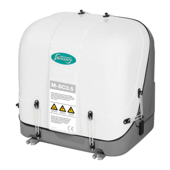
- Page 1 INSTALLATION MANUAL M-SC3.5 - 3000 RPM - Marine diesel generating set 230V / 50Hz Digital Diesel Control WHISPER POWER BV Kelvinlaan 82 9207 JB Drachten Netherlands Tel.: +31-512-571550 Fax.: +31-512-571599 V1. September 2010 www.whisperpower.eu...
-
Page 2: Table Of Contents
DIAGRAMS & DRAWINGS ............................22 DC wiring diagram ............................22 Wiring names and colours ..........................24 AC wiring diagram 230V / 50 Hz ........................25 Remote control panel drawings ........................26 Dimensions M-SC3.5 ............................27 September 2010 / M-SC3.5 / EN... -
Page 3: Installation
For other models see our website: www.whisperpower.eu. plate. A steel base plate is available from Whisper Power as an optional accessory (ref. fig. 30, page 23). To ensure reliability and durability of the equipment, it is very important that the installation is carried out with the 1.2.2... -
Page 4: Ventilation
9 Fuel in 13 Cable fuel lift pump 2 Fuel return 6 Water return 10 Remote cable 3 Exhaust 7 Water in 11 Battery NEG 4 Water out 8 Oil strainer 12 AC cable Figure 2 September 2010 / M-SC3.5 / EN... -
Page 5: Fuel Supply
FUEL FILTERS A fine fuel filter is installed which requires maintenance. Whisper Power advises to install an extra fuel filter/ water fuel separator near the fuel tank. Before starting your generating set for the first time follow the fuel system bleeding procedure in the users manual. - Page 6 3 Prefilter / water separator (optional); 4 Extra fuel lift pump (optional); 5 Fuel tank; 6 Standard fuel lift pump; 7 Standard fuel filter. Figure. 4: Fuel supply (fuel tank is above the generating set) September 2010 / M-SC3.5 / EN...
-
Page 7: Cooling
(1/2"). Install the water strainer in a well accessible engines in motorboats the water scoop is often mounted position, (refer to figure. 5, ref 6) 5 cm above the waterline. against the sailing direction to induce more water intake for cooling. EN / M-SC3.5 / September 2010... - Page 8 On the valve is a little hose to drain a little water that could be spilled from the valve. This hose should go down and may not end under water, because it should ventilate air into the valve to break the siphoning (figure 7). Figure 8 September 2010 / M-SC3.5 / EN...
-
Page 9: Exhaust System
Some mufflers and water locks cause too high back pressure. STANDARD EXHAUST SYSTEM INSTALLATION You are advised to use a Whisper Power generating exhaust system must... - Page 10 2 Water/exhaust separator; 4 Waterlock; Max. length A – B = 2.5 m. (8 ft.) Figure 11: Only after the exhaust / water separator the exhaust hose may have a length up to 7,5m. September 2010 / M-SC3.5 / EN...
- Page 11 Fig.12: Water trap in exhaust system WRONG! Figure 13: Water will collect in the hanging bend of the exhaust gas hose and will cause back pressure EN / M-SC3.5 / September 2010...
-
Page 12: Control System
Fig. 16 details. (There is also available a fully dedicated Masterbus controlled M-SC3.5 MB (41200500). For this model an One can mount the control panel after drilling a hole in the interface in not required to operate in a Masterbus dashboard using the plastic cover. - Page 13 When this is the case consult to the Whisper Power a certain setting. Other names for this second battery are service department for advice.
-
Page 14: Ac Power System (230 Volt)
Be sure that all electrical installations (including all safety generating set is not used. A battery charger is not systems) comply with all required regulations of the local September 2010 / M-SC3.5 / EN... - Page 15 Small pleasure craft in Europe is submitted to The Recreational Craft Directive 94/25/EC. The guidelines of Whisper Power advises the installation of a Whisper this directive refer to (ISO 13297). Power transfer switch as the power source selector. This When the installation comply to this standard the “neutral”...
-
Page 16: Installation Specifications
Connect exhaust system. Open the fuel valve and bleed the fuel system. Ensure there is sufficient fuel. The M-SC3.5 is self bleeding. Connect a siphon breaker or ‘air vent’ into the cooling To check the well functioning release the bleed screw circuit, if necessary. -
Page 17: Installation Specifications M-Sc3.5
12 V DC, max. lift 1 m Cooling indirect cooling Cooling pump raw water Whisper Power self priming impeller pump, PTO driven, type K Minimum water supply 8-10 l/min. Crank case lube oil capacity 1.3 litre + 0.2 oil cooler, total 1.5 litre... -
Page 18: Installation Materials M-Sc3.5
50221522 Hose clamp stainless 10-16 50222020 Copper fuel pipe per meter 50220063 Fuel hose per meter OPTIONAL INSTALLATION MATERIALS • Additional installation parts pos. article no description 40230092 Filter for strainer fuel/water separator September 2010 / M-SC3.5 / EN... - Page 19 Syphon breaker valve 12.5mm (1/2”), complete (including valve assembly) 50221521 Hose clamp stainless 12-20 50220057 Cooling water hose warm water 13x21mm 50221260 Hose connector 12.5mm (1/2”) TOTAL 40230272 SYPHON BREAKER KIT 12.5 MM (1/2") EN / M-SC3.5 / September 2010...
- Page 20 DELTA WATER/GAS SEPARATOR KIT 40 mm OPTIONAL INSTALLATION MATERIALS pos. article no description 50201830 Elbow 90° adapter exhaust hose 50221504 Hose clamp stainless 32-44 mm 50230113 Straight coupling Delta 40mm 50230112 Elbow (45º) Delta 40mm September 2010 / M-SC3.5 / EN...
- Page 21 INSTALLATION SPECIFICATIONS base plate kit Figure 27: installation materials BASE PLATE KIT for M-SC3.5 (3000 rpm) pos. article no description 50230552 Rubber mounting up to 70 kg RAB3 50230012 HD base plate 3500 yellow zinc plated 50211449 Washer spring SP M12...
-
Page 22: Diagrams & Drawings
DIAGRAMS & DRAWINGS DIAGRAMS & DRAWINGS 3.1 DC WIRING DIAGRAM Figure 28a: DC wiring M-SC3.5 grounded September 2010 / M-SC3.5 / EN... - Page 23 DIAGRAMS & DRAWINGS Figure 28b: DC wiring M-SC3.5 ungrounded EN / M-SC3.5 / September 2010...
-
Page 24: Wiring Names And Colours
White 1 mm2 Uac1-N White 1 mm2 Ground relay + White 1 mm2 Battery + 16 mm2 Battery - Black 16 mm2 Earth wire Green/yellow 6 mm2 * Ungrounded versions only (part nr. 51200606) September 2010 / M-SC3.5 / EN... -
Page 25: Ac Wiring Diagram 230V / 50 Hz
DIAGRAMS & DRAWINGS 3.3 AC WIRING DIAGRAM 230V / 50 HZ EARTH AND NEUTRAL NOT CONNECTED 230V 50Hz EARTH AND NEUTRAL CONNECTED 230V 50Hz Figure 29 AC wiring diagram EN / M-SC3.5 / September 2010... -
Page 26: Remote Control Panel Drawings
DIAGRAMS & DRAWINGS 3.4 REMOTE CONTROL PANEL DRAWINGS The remote panel comes in a carton that can be used as a template to drill the mounting hole. Fig. 30 September 2010 / M-SC3.5 / EN... -
Page 27: Dimensions M-Sc3.5
• battery -: 16 mm² black (included) • sea water in: 13 mm • cables: 3x 2.5 mm2 (5 meter included) • air vent connection: 13 mm • remote control: MasterBus communication cable (15 meter included) EN / M-SC3.5 / September 2010... - Page 28 Kelvinlaan 82, 9207 JB Drachten, Netherlands Tel : + 31-512-571550 / Fax : + 31-512-571599 www.whisperpower.eu / info@whisperpower.nl...
Need help?
Do you have a question about the M-SC3.5 and is the answer not in the manual?
Questions and answers