Table of Contents
Advertisement
Advertisement
Table of Contents
Troubleshooting

Related Manuals for wallas XC Duo


Summary of Contents for wallas XC Duo
-
Page 3: Table Of Contents
Connection to a separate tank Wallas fuel tanks Installation instructions for Tank connection 30018 Description Getting Started Stages Installation instructions for Tank connection (XC Duo) Selecting the fuel Combustion gas connections Location in the underframe Location under a window Installing the hoses... - Page 4 XC Duo Contents Installation and initial start-up Device use Ignition First start-up Normal Use Cooker used as a heater, thermostat use Sun-switch (heating) Manual power adjustment (stove/heating) Shutdown High altitude switch Signal lights Things to note about the use of the cooking plate...
-
Page 5: Supplies And Accessories
4300 Bracket set 4310 4320 Cover plate kit 1028 1030 Heat insulation Ø 30 mm, Fiber glass 4350 XC Duo Installation kit 30018 367215 Tank feed through, diesel, 4 m 367216 Tank feed through, diesel, 6 m 1102 4330 368202... -
Page 6: Package Contents
XC Duo Technical information Package contents XC Duo 1 pcs Stove XC Duo 1 pcs Power cable with connector and integrated fuse 15 A (4m) 2 pcs Steel fastener 1 pcs 1 pcs Accessory bag 17735 4 pcs 4 pcs... -
Page 7: Stove Operation
XC Duo Technical information Stove operation The XC Duo a single burner which burns either diesel oil or light furnace oil (diesel heating oil). The stove takes the air needed for the burning process from outside of the vehicle vehicle. -
Page 8: Things To Note When Selecting The Installation Location
The stove should not be installed on top of a refrigerator. The stove will heat its sur- roundings and thus decrease the power of the refrigerator. We recommend that the device be installed by an authorised Wallas Dealer. Things to note when installing pipes, hoses and cables Power cables and fuel hoses must be protected in locations where they are sus- ceptible to mechanical damage due to sharp edges or heat. -
Page 9: Stove Installation
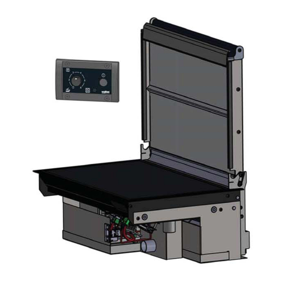
XC Duo Installation Stove installation Saw a cut-out (see picture) for the stove and the control panel in your chosen loca- tion. The length of the control panel cable is 3 m. Ensure that there is suf cient space between the stove and the vertical surface to facilitate installing and detach- ing the device. -
Page 10: Fastening The Device
The steel fasteners can be installed in two ways depending on the thickness of the table board. Push the cover plug (3) on the screw. Tighten the screw (4) rmly against the table board and then tighten the locking nut (5). Always use original Wallas accessories and parts with Wallas equip- ment. D10361B... -
Page 11: Connections Of The Device
XC Duo Installation Connections of the device Things to note about the connections In installation, to make the mounting and demounting for service easier, it is recom- If the installation location is cramped, it is recommend to connect the cabels and the fuel line to the device before mounting the unit to bracket. -
Page 12: Control Panel Installation
XC Duo Installation Control panel installation Cut a suitable installation hole for the control panel in the selected location. Try to install the panel in a vertical surface in a location that will remain dry and in dis- tance from splash water. -
Page 13: Electrical Connections
XC Duo Installation Electrical connections Things to note about the connections The device uses 12 V (nominal) direct current voltage. To minimize current losses, make the power cable as short as possible and avoid joining. The cross-sectional area of the cable is dependent on the length of the power cord. The cross-sectional area of the cable must be consistent all the way from the stove to the battery. -
Page 14: Electrical Connections Of The Device
XC Duo Installation Electrical connections of the device 12 V direct current system Connect the red wire of the power cord to the plus terminal of the battery and the black or blue wire to the minus terminal. A 15 A main fuse must be installed near the battery on the red plus wire of the power cord. -
Page 15: Fuel Connections
Please note that installation of such fuel intake pipe to the original tank of the a tube end where you can connect the fuel tube of XC Duo, you do not need any separate approval. -
Page 16: Installation Instructions For Tank Connection 30018
XC Duo Installation Installation instructions for Tank connection 30018 Description ® Einon (30018) is a leak-proof intake fuel line. Getting Started Parts needed in installation are put in right order and are connected together with a wire. You shall never cut the installation wire , you’ll need it when installing the intake pipe. -
Page 17: Installation Instructions For Tank Connection (Xc Duo
XC Duo Installation Installation instructions for Tank connection (XC Duo) If the fuel will be taken from a separate tank, you must install a tank connection 367215 (4 m) / 367216 (6 m). with fuel line of tank connection fuel set. - Page 18 XC Duo Installation 30015. Filters can be installed in a ø 5 or ø 6 mm plastic. Ensure that the fuel pipes are (accessory) ø 5 mm olive and ø 2 mm support sleeve. For connecting a ø 5 mm fuel hose.
-
Page 19: Selecting The Fuel
XC Duo Installation Selecting the fuel When selecting the fuel type, take note of the temperature limits of each particular actual temperature limits from the fuel supplier. diesel, summer grade, temperature must not fall below –5 °C. diesel, winter grade, temperature must not fall below –24 °C. -
Page 20: Combustion Gas Connections
XC Duo Installation Combustion gas connections Location of the exhaust head Location in the underframe When selecting the location for installing the 4300 of the vehicle and routing of the combustion gas and intake air hoses should be taken into account. Try to keep the hoses as short as possible. Also keep in mind that the combustion gas hose becomes hot. -
Page 21: Location Under A Window
XC Duo Installation Location under a window 4300 shall not be installed under an opening window or closer switch that prevents the hob from being used when the window is open. min. 300 mm min. 400 mm min. 300 mm... - Page 22 XC Duo Installation Removing the plastic frame of the exhaust head The 368202 plastic frame of the 4300 pulling the plastic strips on both sides of the plastic frame outward while pulling the Fixing the hoses on the exhaust head hose clamps supplied with the accessory pack.
- Page 23 XC Duo Installation Installing the exhaust head Orientation of the exhaust head The 4300 Combustion gas exhaust min. 0,3 m Combustion gas exhaust The exhaust gases are removed from the smaller end of the grille in the exhaust head 4300. The smaller end of the grille is located closest to the rear wheel.
- Page 24 XC Duo Installation Fixing to the vehicle bottom There are many possible ways to install the 4300 bottom structure. The 4310 basic chassis installation kit can be used to install the combustion gas frame to most vehicles. The 4330 special cases.
- Page 25 XC Duo Installation Installing the plastic frame on the exhaust head After the metal part of the 4300 that the claws of the plastic strips lock the frame in place. Exhaust head 4300 is a mandatory accessory. Without this part, the combustion will be disturbed.
-
Page 26: Installation And Initial Start-Up
Make sure there is enough ventilation. The hoses must be kept clean during installa- tion. Remember to carefully read the instruc- Use only Wallas fuel hoses. tions for installing, operating and ser- Cut the fuel hoses to the appropriate length vicing each device before installation. -
Page 27: Device Use
XC Duo Operation Device use Ignition The stove turns on and heats automatically. The stove turns on when the power switch (3) is continuously pressed for at least 2 seconds, and the power indicator light (4) turns on, notifying that the stove is ready for use. -
Page 28: First Start-Up
XC Duo Operation First start-up After installation or maintenance, if the fuel line is empty, the heater may not start and might take about 15 minutes. If the heater doens’t ignite the red combustion indicator light will start to blink after start-up. -
Page 29: Sun-Switch (Heating
XC Duo Operation Sun-switch (heating) The sun-switch shuts down the device automatically, if the temperature rises above rise by +7 °C above the set value for a half an hour. If the device has been shut down by the sun-switch, an indicator light (5) blinks on the thermostat. The sun- switch can be turned off temporarily, by turning the temperature control (2). -
Page 30: High Altitude Switch
XC Duo Operation High altitude switch Switch for high altitudes. Switched on when the device is used more than 1300 meters (4200 feet) above sea level. This function increases the amount of combus- tion air in thin air. The high altitude mode is turned on by pressing the heating switch (3) for 10 sec- onds , when you start the unit. -
Page 31: Things To Note About The Use Of The Cooking Plate
XC Duo Operation Things to note about the use of the cooking plate Only use dishes with a smooth bottom so as to not damage the stove top. If you use the cold stove top for other work or chores, be sure to wipe it clean thoroughly after you are done. -
Page 32: Fault Signals And Releasing The Lock
XC Duo Maintenance Fault signals and releasing the lock Colour Blink interval Fault description Yellow Glow failure Yellow Combustion air blower fault Yellow Main blower fault Yellow Undervoltage Yellow Locking; the device locks itself after 2 unsuccessful starts * Yellow... -
Page 33: Maintenance Recommendations
XC Duo Maintenance Maintenance recommendations Cleaning the exhaust head Clean the vehicle’s 4300 may change the burner’s combustion parameters or even prevent the unit from operating altogether. Basic maintenance No hour limit has been set for basic maintenance. The unit should be serviced, if:... -
Page 34: Winter Storage
Spare parts Spare parts list, www.wallas.com When using the XC Duo in winter time, please check regularly that the exhaust head and especially the air intake part of it is out of ice and snow. Remove ice and snow if needed. -
Page 35: Troubleshooting, Locking Indication
XC Duo Maintenance Troubleshooting, locking indication FAULT INDICATION WITH BLINKING LIGHTS Yellow Locking indication RELEASING THE LOCK: The device locks itself after 2 1. When the lights are blinking, switch off unsuccessful starts. the main power at the battery, breaker or in-line switch. -
Page 36: Troubleshooting, Undervoltage
XC Duo Maintenance Troubleshooting, undervoltage FAULT INDICATION WITH BLINKING LIGHTS Yellow Undervoltage The operating voltage in the current connector of the device is below 10,7 V when the unit is in a load. Check the connection of the fuse in the power supply. - Page 37 XC Duo Maintenance FAULT INDICATION WITH BLINKING LIGHTS Check that the device is not in after cooling mode. After cooling mode uses the same signal and it’s not malfunction but a normal procedure. (If it is a malfunction, after 5 minutes...
-
Page 38: Warranty Terms
Warranty does not include any transport costs. (Wallas is a return to base warranty). No warranty repairs are carried out while the d) The customer must provide the following information in writing for warranty service: description of the problem. - Page 39 XC Duo Spare parts XC Duo spare part no spare part no 367501 365318A FUEL PUMP, FC 1 COMBUSTION BLOWER, XC Duo 361071 368057 CONTROL UNIT, XP360 HINGE ROLLER SET 362601 362502 THERMO ELEMENT GLOW PLUG 364015 369007 GASKET FOR T4 THERMO ELEMENT...
-
Page 40: Spare Parts
XC Duo Spare parts D50371B 490541G - 110 -... - Page 41 XC Duo Spare parts 490541G D50371B - 111 -...
- Page 42 490541G D90019 - 112 -...
- Page 43 490541G...
- Page 44 Wallas-Marin Oy Kärrykatu 4 20780 Kaarina Finland Oikeudet muutoksiin pidätetään. We reserve the right to changes. www.wallas.com Änderungen vorbehalten. 490541G...
Need help?
Do you have a question about the XC Duo and is the answer not in the manual?
Questions and answers