wallas 88DU Installation, Operation And Service Instructions
Hide thumbs
Also See for 88DU:
- Operation manual (2 pages) ,
- Operation manual (2 pages) ,
- Installation, operation and service instructions (284 pages)
Table of Contents
Advertisement
Technical information
3468
2466
2069
4m, MAX 8m
Package contents
88DU
1 pcs
Stove 88DU (fuel hose and control panel cable installed)
1
Control panel
1 pcs
1 pcs
2
Power cord with connector (4 m)
2 pcs
3
Iron fastener
1 pcs
Accessory bag
2 pcs
4 pcs
4 pcs
4 pcs
4 pcs
1 pcs
1 pcs
1 pcs
2 pcs
1 pcs
Pipe connection box kit
1 pcs
1 pcs
1 pcs
1 pcs
Fuel fi lter package
1 pcs
4 pcs
2 pcs
2 pcs
1 pcs
1 pcs
Installation, operation and maintenance instructions
88DU
1012
2m
30012
30011
4
Control panel fastening screws 3.5 x 13 (black)
5
Screw for iron fastener M6 x 12 (hexagonal socket 4 mm)
6
Fastening screw M6 x 30 (hexagonal socket 4 mm)
7
Locking nut M6
8
Cover plug
9
Hose binder 20 – 32 mm
10
Fuse box
11
Fuse 15 A (blue)
12
Push on contact 6.3 x 0.8 (yellow)
13
Pipe connection box
14
Hose binder 32 – 50 mm
15
Tightening screw M4 x 8
16
Fuel fi lter
17
Hose binder 8 mm
18
Hose binder 10 mm
19
Rubber hose ø 5 mm
20
Rubber hose ø 6 mm
- 65 -
2448
MAX 2m
MAX 4m
3430
O
28/45mm
3430
MAX 1m
4m
12V
4m
367215
GB
2467
490070GB
Advertisement
Table of Contents

Related Manuals for wallas 88DU


Summary of Contents for wallas 88DU
-
Page 1: Technical Information
MAX 1m 4m, MAX 8m 30012 367215 30011 Package contents 88DU 1 pcs Stove 88DU (fuel hose and control panel cable installed) Control panel 1 pcs 1 pcs Power cord with connector (4 m) 2 pcs Iron fastener 1 pcs... -
Page 2: Stove Operation
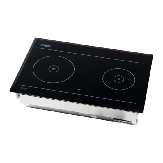
Technical information Stove operation The 88DU is a safe diesel stove with no open fl ame. The stove is equipped with a single burner which burns either diesel oil or light furnace oil. The stove takes the air needed for the burning process from the boat and discharges the resultant smoke with a combustion air blower. -
Page 3: Things To Note When Selecting The Installation Location
Moreover, the stove should not be installed on top of a refrigerator. The stove will heat its surroundings and thus decrease the power of the refrigerator. We recommend that the device be installed by an authorised Wallas service shop. Things to note when installing pipes, hoses and cables Power cables and fuel hoses must be protected in locations where they are sus- ceptible to mechanical damage due to sharp edges or heat. -
Page 4: Stove Installation
88DU Installation Stove installation Saw a cut-out (see picture) for the stove and the control panel in your chosen loca- tion. The length of the control panel cable is 2 m. The stove requires a replacement air opening of at least 100 cm Ensure that the air circulation under the stove is suffi... - Page 5 fl ue gas hose is 2 to 4 metres long, the stove is surrounded by thick thermal insulation, there is another heat source under the stove (e.g. a Wallas oven 86D or a refrig- erator), the climate is particularly warm, the intake connection set 3430 must be installed on the stove.
-
Page 6: Fastening The Device
88DU Installation Fastening the device Place the stove in the installation cut-out and attach the iron fasteners (3) with the screws (5) to the rivet nuts at the ends. After this, install the cover plug (8) on the end of the screw and tighten the iron fasteners against the table with the screw (6). - Page 7 88DU Installation Installation of the fl ue gas pipe Measure the length of the fl ue gas and exhaust pipe from the device to the gas lead-through. Remember to add the required length for the swan neck section. Cut the fl ue gas pipe 30–50 mm longer than the exhaust pipe. This way the pipe will stay in place in the gas lead-through more fi...
-
Page 8: Electrical Connections
88DU Installation ELECTRICAL CONNECTIONS Things to note about the connections The device uses 12V direct current voltage. To minimise current losses, make the power cable as short as possible and avoid jointing. The cross-sectional area of the cable is dependent on the length of the power cord. See table 1. The cross- sectional area of the cable must be consistent all the way from the stove to the battery. -
Page 9: Electrical Connections Of The Device
88DU Installation Electrical connections of the device 12V direct current system Connect the red wire of the power cord to the plus terminal of the battery and the black or blue wire to the minus terminal. A 15 A main fuse must be installed near the battery on the red plus wire of the power cord. -
Page 10: Fuel Connections
88DU Installation FUEL CONNECTIONS Things to note about the connections The standard length of the fuel hose is 4 m (max 8 m). Cut the fuel hose to a length suitable for installation. The lift height of the pump should be less than 2 m; preferably 0.5 – 1 m. -
Page 11: Connection To A Fi Xed Tank
The stove must have a separate connection as well as a fuel fi lter outside the tank. If necessary, the fuel line can be branched off with a T piece to the Wallas diesel-operated device. Installation instructions for Tank connection 30011 (accessory) Make a ø... -
Page 12: Connection To A Separate Tank
130 l 800 x 400 x 600 4130 (accessory) Wallas fuel tanks Installation instructions for Tank connection 367215 (accessory) If the fuel will be taken from a separate tank, you must install a tank connection 367215. There are two methods to install the tank connection to the stove. -
Page 13: Tank-External Fi Lters
88DU Installation Tank-external fi lters Filters can be installed in a ø5 or ø6 mm plastic or ’’ metal pipe. Ensure that the fuel pipes are clean before installing the fi lter. There must be no debris or impurities between the pump and the fi lter as they will clog the pump. The fi lter type must be selected according to the operating conditions and country-specifi... - Page 14 88DU Installation Installation instructions for Solenoid valve 30012 (accessory) The solenoid valve (30012) prevents the tank from emptying in case the fuel line breaks. The fuel fi lter should be installed before the solenoid valve. In a fuel hose with a T branch, the solenoid valve must function with both connect- ed devices.
-
Page 15: Selecting The Fuel
88DU Installation Selecting the fuel When selecting the fuel type, take note of the temperature limits of each particular fuel. The limit values provided here are to be treated as guidelines. Confi rm the actual temperature limits from the fuel supplier. - Page 16 88DU Installation FLUE GAS CONNECTIONS Flue gas lead-throughs Flue gas lead-throughs 2467, 3468 and the closable model 2460 are suitable for this device. All fl ue gas lead-throughs are stainless steel. The ø 28/45 mm lead-throughs fi t the fl ue gas pipe 2448.
- Page 17 88DU Installation SPECIFIC INSTRUCTIONS FOR INDIVIDUAL LEAD-THROUGHS 2467 Side lead-through A side lead-through is installed in the side of the boat or in the transom. In sail boats it is recommended to install it in the transom. The installation always requires a so-called swan neck piece.
- Page 18 88DU Installation 3468 General lead-through You can install the general lead-through in a position of your choice, but ideally the lead-through is installed in a position which allows it to function optimally. 1. If the lead-through is installed in the side of the boat or a deck structure, it should be slightly inclined towards the stern so that the outer surface of the lead-through will be cooled by the thermal current going through it as well as the wind.
- Page 19 88DU Installation 2460 Closable lead-through The cap of the closable lead-through must be detached for installation and seal maintenance by pressing the spring indicated by the arrow in with, for instance, a screwdriver. Take care not to let the screwdriver slip as the spring is very stiff. Hold the cap with your other hand when pressing in the spring.
- Page 20 88DU Installation Insulation kit for a metal-hulled boat An insulation kit must be used to insulate the lead-through from the boat’s metal hull. The insulation kit insulates the fl ue gas lead-through and the device from each other. In fault situations the electric circuit runs between the metal hull and the device.
-
Page 21: Use Of The Stove
88DU Operation Use of the stove The stove starts to heat up automatically when the power switch is turned to the ON position. The yellow current indicator LED will light as soon as the electricity is switched on. The red combustion indicator LED will be lit, when the burner fl ame has been lit and the burning has stabilised after roughly 2.5 –... -
Page 22: First Start-Up
88DU Operation FIRST START-UP After installation or maintenance, if the fuel line is empty, the stove will not necessarily start up on the fi rst try. If this is the case, the red combustion LED will begin to blink roughly 4.5 minutes after start-up. - Page 23 88DU Operation ACCESSORIES Toasting grill 1150 The toasting grill is a handy accessory for toasting bread for breakfast while mak- ing tea on the other cooking plate. Kettle holder set 1012 Kettle holders keep cooking vessels in place on the stove when the boat tilts.
-
Page 24: Things To Note About The Use Of The Cooking Plate
This prevents possible damage due to the food boiling over. Observe the general maintenance recommendations for Wallas equipment when servicing the electronic and mechanical parts of the stove. -
Page 25: Fault Signals And Releasing The Lock
88DU Maintenance Fault signals and releasing the lock Colour Blink interval Fault description Yellow Glow failure Yellow Combustion air blower fault Yellow Cooling blower fault Yellow Undervoltage Yellow Locking; the device locks itself after 2 unsuccessful starts * Overheat 5 minutes after fault indication... -
Page 26: Maintenance Recommendations
If the device uses the same tank as the engine: Observe the engine manufacturer’s recommendation with regard to the fuel type and moisture removal. Only diesel or light furnace oil can be used in Wallas diesel- operated products. If the device has a separate tank: When selecting the fuel type, take note of the temperature limits of each particular fuel. - Page 27 88DU Maintenance Opening the cooling case for maintenance measures Various maintenance measures or inspection require you to open the cooling case. For minor work only the front hatch needs to be opened, but more extensive main- tenance requires the removal of the entire cooling case.
- Page 28 88DU Maintenance The stove does not LOCKING INDICATION do anything. Releasing the lock: 1. Switch to the ON position (indicator lights blink). 2. Disconnect the main power cord (lights go out). 3. Reconnect the main power cord (yellow LED is lit for 1–3 seconds).
- Page 29 88DU Maintenance The stove does not start up LOCKING INDICATION (after two attempts) The pump does not receive Check the wiring of the pump and current pulses. the condition of the overheat The red LED on the circuit board protection.
- Page 30 88DU Maintenance The stove smokes when started up. The glow plug does not Check the battery voltage. receive sufficient current. (The glow plug does not heat up to a sufficient Check the power cord temperature.) connections, joints and the main switch.
- Page 31 Measures to take in the event of a defect: a) Look on the check list on the website (www.wallas.com) to make sure the defect in question is not related to use, i.e. a simple problem not covered by the warranty.
Need help?
Do you have a question about the 88DU and is the answer not in the manual?
Questions and answers