
Related Manuals for WinSystems PPM-C407


Summary of Contents for WinSystems PPM-C407
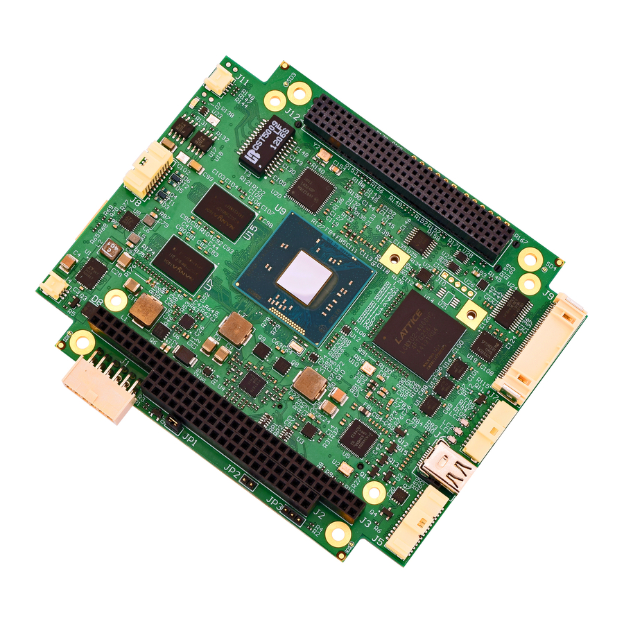
- Page 1 PPM-C407 ® Intel Atom™ E3800 PC/104-Plus Single Board Computer with Digital I/O Product Manual WinSystems, Inc. | 715 Stadium Drive, Arlington, Texas 76011 | 817-274-7553 | info@winsystems.com | www.winsystems.com...
-
Page 2: Revision History
No part of this document may be copied or reproduced in any form or by any means without the prior written consent of WinSystems, Inc. The information in the document is subject to change without notice. The information furnished by WinSystems, Inc. in this publication is believed to be accurate and reliable. -
Page 3: Table Of Contents
PPM-C407 Table of Contents Before You Begin ......... 1 Warnings . - Page 4 PPM-C407/ 7.8.6 J7 VGA ..............22 7.8.7 J8 USB .
-
Page 5: Before You Begin
Refer to the WinSystems website for other accessories (including cable drawings and pinouts) that can be used with your PPM-C407. Functionality The PPM-C407 is a full-featured embedded single board computer that operates in the Windows 7, Windows 8, Windows CE, Linux and DOS environments. It features an ®... -
Page 6: Features
PPM-C407/Features RS-232. channels. Refer to “Features” on page 2 and “General Operation” on page 4 for specific information. NOTE WinSystems can provide custom configurations for OEM clients. Please contact an Application Engineer for details. Features The PPM-C407 provides the following features: Single Board Computer •... - Page 7 PPM-C407/Features Digital Input/Output (DIO) • 24 lines (bi-directional) provided within the Lattice Semiconductor Corp., MachXO2™ FPGA (field-programmable gate array) interfaced to the processor with the Low Pin Count (LPC) interface. • 5 V tolerant signals • Each line programmable for input, output, or event sense •...
-
Page 8: General Operation
PPM-C407/General Operation General Operation System Block Diagram The PPM-C407 is a single-board computer (SBC). It is a full-featured embedded system with a variety of onboard I/O options. The following figure is a simplified system block diagram of the PPM-C407. DDR3L... -
Page 9: Specifications
Linux, Windows and other x86 operating systems can be initialized from the SATA, mSATA, or USB interfaces. This provides flexible data storage options. Specifications The PPM-C407 adheres to the following specifications and requirements: PPM-C407 Specifications Electrical +5 V DC ±5% required... - Page 10 RoHS Compliant Operating Systems Runs 32/64-bit Windows, Linux, and other x86-compatible operating systems. Additional Accessories Standoff kits are available and recommended for use with the PPM-C407. • KIT-PCM-STANDOFF-4: Four piece Nylon Hex PC/104 Standoff Kit • KIT-PCM-STANDOFF-B-4: Four piece Brass Hex PC/104 Standoff Kit...
-
Page 11: Configuration
PPM-C407/Configuration Configuration This section describes the PPM-C407 components and configuration. Component Layout The PPM-C407 provides components on the top and bottom of the board. 7.1.1 Top View 1 2 3 JP3 JP4 v1.0 www.winsystems.com Page 7... - Page 12 PPM-C407/Configuration Top View Components Item Description Reference Power Connector page 16 PC/104 Bus (C/D, 16-bit ISA bus also includes J3) Connector page 17 PC/104 Bus (A/B, 8-bit ISA bus) Connector page 17 External Battery Connector page 19 LVDS and Audio Connector...
-
Page 13: Bottom View
PPM-C407/Configuration 7.1.2 Bottom View J504 J505 J503 D504 J500 J501 Bottom View Components Item Description Reference J500 Backlight page 28 J501 Mini PCIe/mSATA Connector page 29 J503 Serial ATA (SATA) page 31 J504 Digital Input/Output page 32 J505 Ethernet page 33... -
Page 14: I/O Port Map
The PPM-C407 uses plug-and-play (PnP) BIOS resource allocation. Care must be taken to avoid contention with resources allocated by the BIOS. The PPM-C407 utilizes a Low Pin Count to Industry Standard Architecture bridge (LPC to ISA Bridge) to address the PC/104 bus. Most legacy PC/104 modules are I/O mapped and function as expected. -
Page 15: Interrupt Map
IRQs in the BIOS CMOS configuration for use by legacy devices. The PCIe/PnP BIOS will use unreserved IRQs when allocating resources during the boot process. The following tables contain the IRQ resources as used by the PPM-C407. IRQ resources... - Page 16 Bit 6 Bit 7 WinSystems does not provide software support for implementing the Interrupt Status Register to share interrupts. Some operating systems, such as Windows XP and Linux, have support for sharing serial port interrupts (see your specific operating system’s documentation for any available examples). You will need to implement the appropriate software to share interrupts for the other devices.
-
Page 17: Register Definitions
PPM-C407/Configuration Register Definitions The PPM-C407 uses the WinSystems exclusive application-specific integrated circuit (ASIC), the WS16C48. This device provides 48 lines of digital I/O. There are 16 unique registers within the WS16C48. The following table summarizes the registers. I/O Address Offset... -
Page 18: Page/Lock
PPM-C407/Configuration 7.4.3 PAGE/LOCK This register serves two purposes. The upper two bits (D6 and D7) select the register page in use. Bits 0-5 allow for locking the I/O ports. Write a 1 to the I/O port position to prohibit further writes to the corresponding I/O port:... -
Page 19: Watchdog Timer
PPM-C407/Configuration Watchdog Timer The PPM-C407 features an advanced watchdog timer which can be used to guard against software lockups. Two interfaces are provided to the watchdog timer. The Advanced interface is the most flexible and recommended for new designs. The other interface option is provided for software compatibility with older WinSystems single board computers. -
Page 20: Real-Time Clock/Calendar
Most embedded systems use this type of power supply (default setting). Connectors 7.8.1 J1 Power Connector Use this connection to supply power to the PPM-C407. Set Jumper JP1 (see “JP1 AT/ ATX Power Mode” on page 33) to select the type of power supply operation (AT or ATX). v1.0 www.winsystems.com... -
Page 21: J2 Pc/104 Bus (C/D, 16-Bit Isa Bus Also Includes J3) Connector
J3 PC/104 bus (A/B, 8-bit ISA bus) Connector The PC/104 bus is electrically equivalent to the 16-bit ISA bus. Standard PC/104 I/O cards can be populated on PPM-C407’s connectors, located at J2 and J3. The interface does not support hot swap capability. - Page 22 DACK1# MASTER# SD14 SA13 DRQ1 SD15 SA12 REFRESH# SA11 BCLK SA10 IRQ7 IRQ6 IRQ5 IRQ4 IRQ3 #: Active Low Signal DACK2# B10 and C19 are key locations. WinSystems uses key pins as connections to GND. BALE v1.0 www.winsystems.com Page 18...
-
Page 23: J4 External Battery Connector
No keys in connector and no cut pins. 7.8.3 J4 External Battery Connector An optional external battery, connected to J4, supplies the PPM-C407 board with standby power for the real-time clock and CMOS setup RAM. An extended temperature lithium battery is available from WinSystems, part number: •... -
Page 24: J5 Lvds And Audio Connector
BAT-LTC-E-36-27-2 7.8.4 J5 LVDS and Audio Connector NOTE The PPM-C407 has one VGA, one DisplayPort and one Low-Voltage Differential Signaling (LVDS) interface. Only two of the three outputs may be active simultaneously. The LVDS portion of this connector can be configured (see “JP4 Low-Voltage Differential Signaling (LVDS)”... - Page 25 LVDS: Molex 501189-3010 housing with Molex 501193-2000 crimp pins. • Backlight: Molex 501330-1100 with Molex 501334-0000 crimp pins. • WinSystems cables simplify connections to the board: – CBL-LVDSAB-005-12: LVDS/Audio & Bklt to 7" Ampire with Audio Jacks – CBL-LVDSB-006-12: LVDS & Bklt to 7" Ampire without Audio –...
-
Page 26: J6 Mini Displayport
PPM-C407/Configuration 7.8.5 J6 Mini DisplayPort NOTE The PPM-C407 has one VGA, one DisplayPort and one Low-Voltage Differential Signaling (LVDS) interface. Only two of the three outputs may be active simultaneously. Layout and Pin Reference: NAME DESCRIPTION PIN NAME DESCRIPTION Ground... -
Page 27: J8 Usb
WinSystems cable CBL-VGA-002-12 (Pico-Clasp to DB-15) simplifies this connection to the board. 7.8.7 J8 USB The PPM-C407 provides four USB2.0 ports with Littlefuse PGB1010603MR (WS G607- 0013-004) ESD surge protection and Murata DLW21HN900SQ2L common mode noise suppressors (WS G605-1014-000). The TI TPS2505B1RGWR (WS G673-0025-131) USB power switch is used to enhance the stability of powering USB devices. -
Page 28: J9 Serial Ports
PPM-C407/Configuration 7.8.8 J9 Serial Ports The PPM-C407 provides four serial ports through the Lattice MachX02 FPGA interfaced to the processor with the Low Pin Count (LPC) interface. Two serial ports support RS232, RS422 and RS485 protocols (using the Exar SP339E multi-protocol transceiver). - Page 29 RS-232 transceivers have charge pumps to generate the plus and minus voltages so the PPM-C407 only requires +5 V to operate. Each port is set up to provide internal diagnostics such as loopback and echo mode on the data stream. An independent, software programmable baud rate generator is selectable from 50 through 115.2 kbps.
-
Page 30: J11 Ethernet External Leds
PPM-C407/Configuration Matching connection: Molex 503110-4000 housing with Molex 501930-1100 crimp pins. WinSystems cables simplify connections to the board: • CBL-SER4-000-14: Duo-Clasp to unterminated • CBL-SER4-001-12: Duo-Clasp to Duo-Clasp • CBL-SER4-002-12: Duo-Clasp to 4xDB9 (shown) 7.8.9 J11 Ethernet External LEDs On-board Ethernet activity signals are provided at this connector. These activity signals are also available off-board for enclosures or other applications that have remote mounting requirements. -
Page 31: J12 Pc/104-Plus (Pci Bus)
PPM-C407/Configuration 7.8.10 J12 PC/104-Plus (PCI bus) The PC/104-Plus is electrically equivalent to the 33 MHz PCI bus. Interface is PC/104- Plus version 2.0 compliant. Layout and Pin Reference: RESERVED AD00 VI/O AD02 AD01 AD05 AD04 AD03 C/BE0# AD007 AD06 AD009... -
Page 32: J500 Backlight
The backlight interface terminates at a Molex 501568-0807, 1x8, 1 mm pitch (Pico- Clasp™) vertical locking header connector (WS G650-2008-6F0). Matching connector: Molex 501330-1100 with Molex 501334-0000 crimp pins. WinSystems cables simplify connections to the board: • CBL-LVDSAB-005-12: LVDS/Audio & Backlight to 7" Ampire with Audio Jacks •... -
Page 33: J501 Mini-Pcie/Msata Connector
PPM-C407/Configuration 7.8.12 J501 Mini-PCIe/mSATA Connector The PPM-C407 provides a mini-PCIe socket to support a variety of peripherals as available in this format. The socket alternatively supports a mSATA device in this socket. A sense circuit identifies the type of device present in the socket and auto- switches to handle either type. - Page 34 PPM-C407/Configuration To install a miniPCIe/mSATA into J501: 1. Insert the miniPCIe/mSATA 2. Push the free end of the card toward the circuit board and then secure it with two (2 mm) screws (WinSystems P/N: G527-0000-400). v1.0 www.winsystems.com Page 30...
-
Page 35: J503 Serial Ata (Sata)
PPM-C407/Configuration 7.8.13 J503 Serial ATA (SATA) The PPM-C407 provides a SATA interface to support connection of a variety of SATA devices. Layout and Pin Reference: Name The SATA interface terminates at an industry standard 7-pin, right angle SATA connector Molex 47080-4005 (WS G650-7007-600). WinSystems cable CBL-SATA-701-20 simplifies connection to the board. -
Page 36: J504 Digital Input/Output
PPM-C407/Configuration 7.8.14 J504 Digital Input/Output The PPM-C407 supports 24 lines of digital input/output (DIO) via the Lattice MachX02 FPGA interfaced to the processor with the Low Pin Count (LPC) interface. These lines maintain the WinSystems standard DIO register definition and by using the TI TXS0108E level converters, all signals are 5 V tolerant. -
Page 37: J505 Ethernet
MX3_N The Ethernet connection is a Samtec TFM-105-02-L-DH, 2x5, 0.05" pitch locking header connector (WS G650-2010-5H0A). Matching connector: Samtec ISDF-05-D-M housing with Samtec CC03L-2830-01-G crimp pins. WinSystems cables simplify connection to the board: • CBL-ENET1-302-12: RJ45 Jack (shown) • CBL-ENET1-303-12: RJ45 Plug Jumpers Jumper Part Number SAMTEC 2SN-BK-G applies to all jumpers. -
Page 38: Jp3 Basic Input/Output System (Bios) Programming Defaults
PPM-C407/Configuration 7.9.2 JP3 Basic Input/Output System (BIOS) Programming Defaults If you have saved EEPROM values that prevent you from accessing BIOS menus, the board can be reset to factory defaults as follows: 1. Turn the system off. 2. Install the jumper at JP3. -
Page 39: Led Indicators
PPM-C407/Configuration 7.10 LED Indicators Description Indicates when an Ethernet activity occurs Indicates when the board is in stand-by power states (S3, S4, or S5) Indicates when the board is in the run power state (S0) and all power supplies are good D504 Indicates when a user defined event occurs. -
Page 40: Bios
BIOS General Information The PPM-C407 includes a BIOS from Phoenix Technologies to assure full compatibility with PC operating systems and software. The basic system configuration is stored in battery backed CMOS RAM within the clock/calendar. As an alternative, the CMOS configuration may be stored in EEPROM for operation without a battery. -
Page 41: Bios Screens
PPM-C407/BIOS BIOS Screens The following BIOS screens contain the options and sample settings for the PPM-C407. Your actual configuration may differ from the screens shown here. Use care when modifying BIOS settings. Main v1.0 www.winsystems.com Page 37... - Page 42 PPM-C407/BIOS Main: System Information Main: Boot Features v1.0 www.winsystems.com Page 38...
- Page 43 PPM-C407/BIOS Main: Error Manager Advanced v1.0 www.winsystems.com Page 39...
- Page 44 PPM-C407/BIOS Advanced: CPU Configuration Advanced: CPU Configuration: CPU Power Management v1.0 www.winsystems.com Page 40...
- Page 45 PPM-C407/BIOS Advanced: Uncore Configuration Advanced: System Component v1.0 www.winsystems.com Page 41...
- Page 46 PPM-C407/BIOS Advanced: Super I/O Configuration Advanced: South Cluster Configuration v1.0 www.winsystems.com Page 42...
- Page 47 PPM-C407/BIOS Advanced: South Cluster Configuration: PCI Express Configuration Advanced: South Cluster Configuration: USB configuration v1.0 www.winsystems.com Page 43...
- Page 48 PPM-C407/BIOS Advanced: South Cluster Configuration: Audio Configuration Advanced: South Cluster Configuration: SATA Drives v1.0 www.winsystems.com Page 44...
- Page 49 PPM-C407/BIOS Advanced: South Cluster Configuration: LPSS & SCC Configuration Advanced: South Cluster Configuration: Miscellaneous Configuration v1.0 www.winsystems.com Page 45...
- Page 50 PPM-C407/BIOS Advanced: Security Configuration Advanced: Power Management v1.0 www.winsystems.com Page 46...
- Page 51 PPM-C407/BIOS Advanced: Thermal Configuration Advanced: SMBIOS Event Log v1.0 www.winsystems.com Page 47...
- Page 52 PPM-C407/BIOS Advanced: SMBIOS Event Log: View SMBIOS event log Advanced: Memory ECC Error Logging v1.0 www.winsystems.com Page 48...
- Page 53 PPM-C407/BIOS Security Boot v1.0 www.winsystems.com Page 49...
- Page 54 PPM-C407/BIOS Exit v1.0 www.winsystems.com Page 50...
-
Page 55: Cables
PPM-C407/Cables Cables WinSystems cables and batteries simplify connection to the PPM-C407. The following table lists available items. Item Part Number Connection Description CBL-PWR-700-18 See “J1 Power Connector” on Power connection page 16. CBL-LVDSAB-005-12 LVDS/Audio and Backlight to 7" Ampire with Audio Jacks CBL-LVDSB-006-12 LVDS and Backlight to 7"... -
Page 56: Software Drivers
PPM-C407/Software Drivers 10. Software Drivers Go to www.winsystems.com for information on available software drivers. v1.0 www.winsystems.com Page 52... -
Page 57: Appendix A. Best Practices
PPM-C407. Use Proper Power Connections (Voltage)—When verifying the voltage, measure it at the power connector on the PPM-C407. Measuring it at the power supply does not account for voltage drop through the wire and connectors. - Page 58 Power Supply OFF—The power supply should always be off before it is connected to the I/O Module. Do not hot-plug the PPM-C407 on a host platform that is already powered. I/O Connections OFF—I/O Connections should also be off before connecting them to the embedded computer modules or any I/O cards.
- Page 59 C407 on the mounting standoffs. Sliding the board around until the standoffs are visible from the top can cause component damage on the bottom of the board. Do Not Bend or Flex the PPM-C407—Bending or flexing can cause irreparable damage. Embedded computer modules are especially sensitive to flexing or bending around Ball Grid Array (BGA) devices.
- Page 60 I/O board to be damaged beyond repair. Conformal Coating Applying conformal coating to a WinSystems product will not in itself void the product warranty, if it is properly removed prior to return. Coating may change thermal characteristics and impedes our ability to test, diagnose, and repair products. Any coated product sent to WinSystems for repair will be returned at customer expense and no service will be performed.
-
Page 61: Appendix B. Mechanical Drawings
PPM-C407/Mechanical Drawings Contact an Applications Engineer—If a diagram or chart in a manual does not seem to match your board, or if you have additional questions, contact a WinSystems Applications Engineer at: +1-817-274-7553. Appendix B. Mechanical Drawings PC/104-Plus SBC E38XX without heatsink 95.89 mm... - Page 62 PPM-C407/Mechanical Drawings PC/104-Plus SBC E38XX with heatsink 95.89 mm 90.81 mm 87.63 mm 8.26 mm 5.08 mm 0 mm Ø 3.18 mm (4X) 30.00 mm 11.05 mm 0 mm 1.98 mm 10.16 MAX. v1.0 www.winsystems.com Page 58...
-
Page 63: Appendix C. Power-On Self-Test (Post) Codes
PPM-C407/Power-on Self-Test (POST) Codes Appendix C. Power-on Self-Test (POST) Codes If the system hangs before the BIOS can process the error, the value displayed at the I/O port address 80h is the code of the last successful operation. In this case, the screen does not display an error code. - Page 64 PPM-C407/Power-on Self-Test (POST) Codes Table C–1: Basic Post Codes (Continued) Code Symbol Description EBC interpret EMBEDDED_CONTROLLER Embedded/Keyboard Controller driver ERROR_LOG Error Manager, Error Log, SERR support FILESYSTEM Enhanced FAT filesystem FIRMWARE_DEVICE Generic firmware device (flash part) driver FIRMWARE_VOLUME Firmware volume related drivers (fault tolerant update, simple file sys-...
- Page 65 PPM-C407/Power-on Self-Test (POST) Codes Table C–1: Basic Post Codes (Continued) Code Symbol Description PPI_NEEDED (unused) PROGRESS_INDICATOR Progress bar support in Boot Manager PS2_KEYBOARD PS/2 keyboard driver PS2_MOUSE PS/2 mouse driver RESET Reset platform via port CF9h Standard ISA RTC support...
- Page 66 PPM-C407/Power-on Self-Test (POST) Codes Table C–1: Basic Post Codes (Continued) Code Symbol Description USER_MANAGER User manager driver (PBA, security) VARIABLE_DEFAULT (unused) VARIABLE_SERVICES Variable services Simple Text and GOP on legacy VGA Option ROM APEI ACPI APEI support (aka WHEA) CSM_PREPARETOBOOT_ENTRY CSM "Prepare to boot"...
- Page 67 PPM-C407/Power-on Self-Test (POST) Codes Architectural Diagnostic Codes Architectural Diagnostic diagnostic codes describe important events in the BIOS initialization sequence. Table C–2: Architectural Diagnostic Codes Code Symbol Description SEC_ENTRY SEC phase entry (reset vector) SEC_EXIT SEC phase exit PEI_ENTRY PEI phase entry (PEI dispatch)
- Page 68 PPM-C407/Power-on Self-Test (POST) Codes Progress and Error Codes Progress and error codes are only displayed on POST diagnostic displays that show four digits. On these displays, the most significant two digits show the progress or error code from the table in this section (Progress and Error Codes), while the least significant two digits show the diagnostic code (see tables above).
-
Page 69: Appendix D. Warranty Information
WinSystems, provided that the warranty, if any, may be assigned. The sole obligation of WinSystems for any breach of warranty contained herein shall be, at its option, either (i) to repair or replace at its expense any materially defective Products or Software, or (ii) to take back such Products and Software and refund the Customer the purchase price and any license fees paid for the same.
Need help?
Do you have a question about the PPM-C407 and is the answer not in the manual?
Questions and answers