Citizen CMP-10 User Manual
Hide thumbs
Also See for CMP-10:
- Command reference manual (80 pages) ,
- User manual (41 pages) ,
- Command reference (5 pages)
Table of Contents
Advertisement
Quick Links
Advertisement
Table of Contents

Related Manuals for Citizen CMP-10


Summary of Contents for Citizen CMP-10
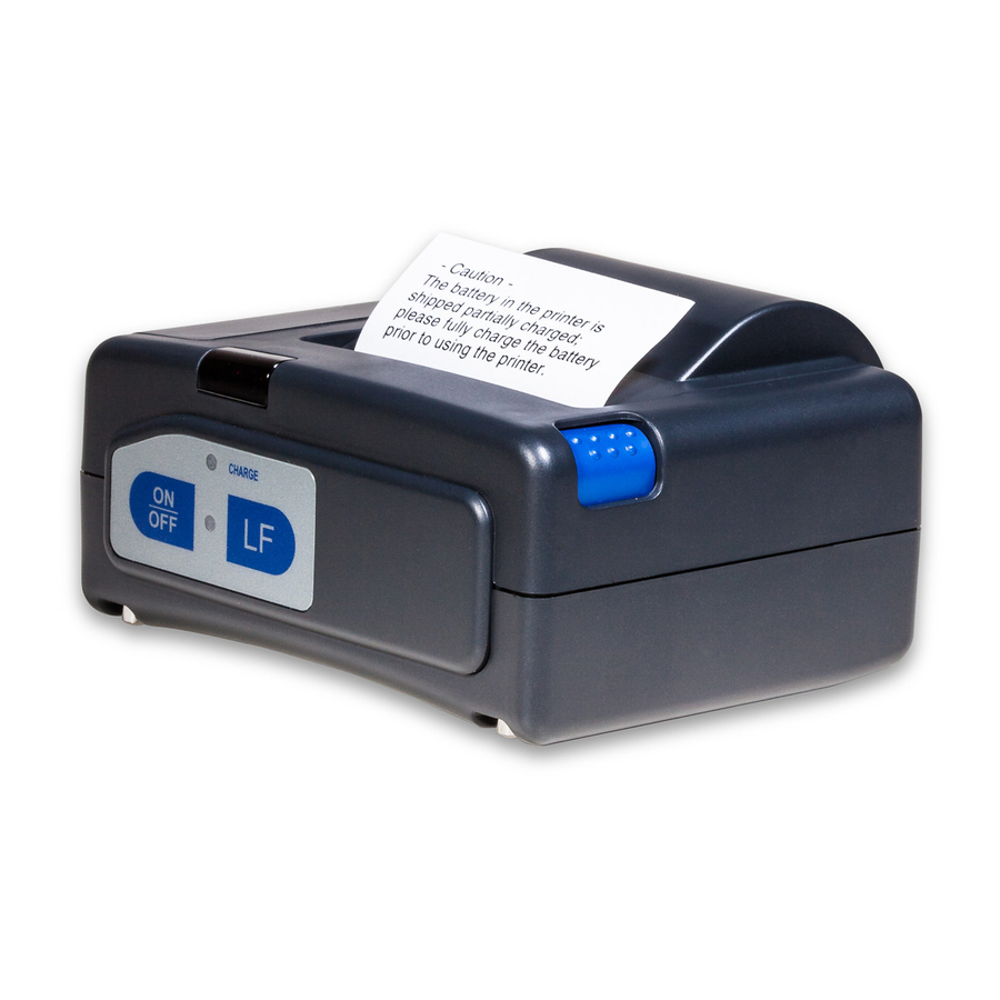
- Page 1 MOBILE THERMAL PRINTER MODEL CMP-10 CMP-10BT User’s Manual...
-
Page 2: Declaration Of Conformity
Declaration of Conformity This printer conforms to the following Standards: Low Voltage Directive 73/23/EEC, 93/68/EEC, EMC Directive 89/336/EEC, 92/31/EEC, 93/68/EEC and the R&TTE Directive 1999/5/EC. : EN60950 : EN55022 Class B EN61000-3-2 EN61000-3-3 EN55024 R&TTE: EN300328 EN301489-1, -17 This declaration is applied only for 230V model. For Unites States In order to comply with FCC radio-frequency radiation exposure guidance for an uncontrolled exposure, this device and its antenna must not be co-located or... -
Page 3: General Precautions
GENERAL PRECAUTIONS G Before using this product, be sure to read through this manual. After having read this manual, keep it in a safe, readily accessible place for future reference. G The information contained herein is subject to change without prior notice. -
Page 4: Safety Precautions
SAFETY PRECAUTIONS About Pictogram Precautions and notices necessary to follow for preventing hazards to the user or other person or their properties are defined as shown below. Hazards and degrees of damage that may be caused by ignoring the instructions are categorized as shown below. - Page 5 Precautions in Handling Printer WARNING G If the product is kept in use under abnormal condition such as generation of heat, smoke, or abnormal odor, a fire may occur. Immediately turn the printer power off, remove the battery, and contact our service agent. G If any foreign matter (metal tip, water, liquid) enters the product, immediately turn the printer power OFF, remove the battery, and contact our service agent.
- Page 6 Precautions on Using Printer WARNING G Do not touch the print head or paper cutter while replacing print paper. Heated print head may cause burn. The cutter may cause injury to the hand. CAUTION G Use of print paper other than specified may result in not only deteriorated print quality but shortened life of print head (printing portion).
- Page 7 Precautions on Using Battery DANGER G Entering battery liquid may result in loss of eyesight. Immediately wash eyes with fresh water and get medical care. G Keep the following in mind when handling battery. Otherwise, liquid leakage, heat generation, and explosion may result. •...
- Page 8 CAUTION G Do not dip battery in water or sea water. Wet battery may generate heat or may be subject to corrosion. G Do not use or leave battery at high temperature. Using or leaving battery in a place of high temperature may result in liquid leakage, deteriorated performance, or shortened lifetime.
- Page 9 Precautions on Using Thermal Paper (Print Paper) CAUTION G Print density may change with the kind of print paper. Print density is adjusted by the Print Density Set command in Command Reference. For details, refer to Command Reference (Separate sheets). G Observe the following when using thermal paper.
- Page 10 Precautions on Using Special Serial Cable WARNING G With one side of the connector connected to this product, do not touch the metal part of the other connector. CAUTION G Static electricity may cause breakdown of internal circuit of this product.
-
Page 11: Table Of Contents
THE TABLE OF CONTENTS 1. INTRODUCTION ............. 11 1.1 Features ................11 1.2 Included and Optional Accessories ......... 12 1.3 Type Classification ............12 2. GENERAL SPECIFICATIONS .......... 13 3. EXPLANATION OF PRINTER PARTS ......16 3.1 LED Indicators ..............16 3.2 Communication Port and Switch ........ - Page 12 7. MAINTENANCE AND SERVICE ........33 8. APPENDIX HANDLING BELT CLIP KIT ......34 8.1 How to Mount Belt Clip ............ 34 8.2 Mounting Rubber Feet ............34 — 10 —...
-
Page 13: Introduction
1. INTRODUCTION CMP-10 is a compact, full featured portable line thermal printer, which can be used in a large variety of job environments ranging from door-to- door sales through small and mid-sized catering establishments, car- rentals, parking lots, field services to on-board sales on land, sea and air. -
Page 14: Included And Optional Accessories
4: Max φ40 mm Destination (AC adapter and characters) E: For Europe etc. J: For Japan U: For North America Model CMP-10: Standard model CMP-10BT: Built-in Bluetooth model This user’s manual is compiled for E/U destination model. — 12 —... -
Page 15: General Specifications
58 ±0.5 mm 60 - 65 µm Paper thickness Recommended paper TF50-KS-E2D (Nippon Paper) Paper roll maximum diameter 40 mm (CMP-10-×4), 50 mm (CMP-10-×5) Minimum core diameter 8 mm Interfaces IrDA version 1.0 Bluetooth version 1.1 Serial interface (by serial cable - option) - Page 16 Feature Parameters Bluetooth interface Frequency band range: 2.4 GHz (2400 - 2483.5 MHz) (CMP-10BT only) The maximum transmission rate: 115200 bps Output class: Class 2 Communication distance: About 10 m The transmission frequency: 79CH from 2402 MHz at intervals of 1 MHz Modulation method: FSK The reception frequency: 79CH from 2402 MHz at intervals of 1 MHz...
- Page 17 Feature Parameters AC adapter Model: 10AD-JU (for Japan, USA, and Canada) 10AD-E (Europe) Input voltage 90 V - 264 V AC Output voltage 9.0 V DC 1.0 A Operating environment Temperature: 5 – 40°C Humidity: 35 – 80% RH (No dew condensation) Storage environment Temperature: –20 –...
-
Page 18: Explanation Of Printer Parts
3. EXPLANATION OF PRINTER PARTS 3.1 LED Indicators (1) Charge LED RED on: Battery is charging GREEN on: Battery is Fully charged (2) Power (Error) LED GREEN on: Lights when printer is powered ON. RED/GREEN blinks fast: No paper or cover open. RED/GREEN blinks slow: Print head is overheated or macro is in process and awaiting LF switch operation. -
Page 19: Communication Port And Switch
3.2 Communication Port and Switch (3) IrDA interface unit Receives data from host and transmits printer status. For communication with IrDA communication, refer to 4.3. (4) Serial port For serial cable (option) connection to host. For the method of communication with cable and connecting cable, refer to 4.4. -
Page 20: Inside Of Paper Cover
3.3 Inside of Paper Cover (10) (11) (10) Paper feed roller Feeds paper through the printing mechanism. (11) Printing (thermal) head Records print data on the thermal paper. 3.4 Buzzer The built-in buzzer sounds in the following cases. When low battery is detected (sounds 3 times) When magnetic card was successfully read (sounds once) When buzzer command is sent (the number of sounding times is controllable) -
Page 21: Bottom Surface And Battery Cover
3.5 Bottom Surface and Battery Cover (12) (14) (13) (12) Belt clip Attaches to the printer on your belt. (Not installed at the time of shipment. To use the belt clip, please install the belt clip by yourself.) (13) Strap holder Metals for holding a strap. -
Page 22: Dimensions And Views
3.6 Dimensions and Views (Unit: mm) DC Jack — 20 —... -
Page 23: Operation
4. OPERATION 4.1 Replacing the Paper Roll Press Cover Open switch (1). Open Paper Cover (2). Place the new paper roll as shown on illustration and pull out enough paper to reach the control panel of the printer (3). Close the Paper Cover. If data to be printed still exists, press the LF switch to resume printing. -
Page 24: Method Of Charging
4.2 Method of Charging If any of the following conditions occur, charging the battery is required. • “Low Battery” is printed. • The buzzer sounds 3 times. To charge the battery, plug the connector of the AC adapter to the DC jack of the printer and the AC adapter to the AC outlet. -
Page 25: Communication By Irda
4.3 Communication by IrDA For IrDA communication, DIP switch setting needs to be set for IrDA. Set the infrared port of the device to face straight to the printer’s infrared port. Communication is available in the range of 15° up, down, left, and right. Avoid blocking between the printer and the device to be connected. -
Page 26: Communication Via Serial Port (Cable)
4.4 Communication Via Serial Port (Cable) For communication with RS-232C, prepare dedicated serial cable. Open the serial port cover and while holding the connector with the wording marked “Push” faciing upward, insert the connector into the serial port. Here, hold the connector with the surface marked “Push” down. Connect the other end of the cable of the cable to the device to be connected. -
Page 27: Communication By Bluetooth
4.5 Communication by Bluetooth For the Bluetooth communication, it is necessary to choose CMP-10BT and set the DIP switches for Bluetooth. As built-in Bluetooth module supports Serial Port Profile, host machine needs to communicate with CMP-10BT based on serial port profile. Please refer to the software manual of the host machine for the details. -
Page 28: Removing The Battery Pack
4.7 Removing the Battery Pack 1. Set the printer Power switch to OFF and unplug the AC adapter from printer. 2. Remove the battery cover by (1) pressing the battery cover as shown in the figure, lift it upward. 3. Remove cover as shown in the illustration. 4. -
Page 29: Installing The Battery Pack
4.8 Installing the Battery Pack 1. Insert the battery connector to the connector of the printer. 2. Insert the battery connecting cable into the opening above the battery connector. Confirm that the battery connector is seated deeply. 3. Insert the battery into its compartment. 4. -
Page 30: Dip Switch Setting
* Default setting of CMP-10BT There are not “No. 1”, “No. 2”, “ON” or “OFF” signs on actual case like the above drawing. Standard CMP-10 does not have Bluetooth function and the DIP switches are not effective. — 28 —... -
Page 31: Function
5. FUNCTION 5.1 Auto Power OFF Power is automatically cut off after a specified period of time, during which no command is sent to the printer and the LF switch has not been pressed. The default setting of this time duration is 10 minutes, however, the period can be custom set by the user with a special command to the printer. -
Page 32: Monitoring The Print Head Overheating
5.4 Monitoring the Print Head Overheating If the temperature exceeds 65°C for some reason, the printer automatically stops printing with Power LED indication of “Error” to protect the print head. If the head temperature returns to 60°C or below, the printer is ready for printing. -
Page 33: List Of Commands
6. LIST OF COMMANDS Sounds the Buzzer Horizontal Tab Command Printing and Paper Feed Command Print one line Command ESC RS Sounds the Buzzer ESC SP Setting the right space amount of the character ESC ! Collective Specifying Printing Mode ESC $ Specifying the Absolute Positions ESC %... - Page 34 ESC a Aligning the characters ESC c5 Enabling/Disabling Panel Switches ESC d Printing and Feeding the paper by n lines ESC v Transmitting the printer status ESC x Selecting the time interval for automatically switching Off the printer ESC { Specifying/Canceling the Inverted Characters GS ) Setting of printer flags...
-
Page 35: Maintenance And Service
7. MAINTENANCE AND SERVICE For information on maintenance and service, please contact your CBM dealer or at the following addresses: Northern America Other Areas CBM America Corpora-on Japan CBM Corporation Service Center Information Systems Division 363 Van Ness Way CBM Bldg. 5-68-10, Nakano Suite 404 Nakano-ku, Tokyo 164-0001, Torrance, CA 90501, U.S.A... -
Page 36: Appendix Handling Belt Clip Kit
8. APPENDIX HANDLING BELT CLIP KIT This kit consists of a belt clip, two screws, and two rubber feet. 8.1 How to Mount Belt Clip Mount the belt clip in the square frame using the two screws supplied. The direction of the belt clip should be as per the drawing below. Note: Do not use screws without mounting the belt clip. - Page 37 MEMO — 35 —...
- Page 38 MEMO — 36 —...
- Page 39 MEMO — 37 —...
- Page 40 Information Systems Division CBM Bldg., 5-68-10, Nakano, Nakano-ku, Tokyo 164-0001, Japan Tel: (+81-3) 5345-7540 Fax: (+81-3) 5345-7541 01E-0408 Printed in Korea...
Need help?
Do you have a question about the CMP-10 and is the answer not in the manual?
Questions and answers