Table of Contents
Advertisement
Quick Links
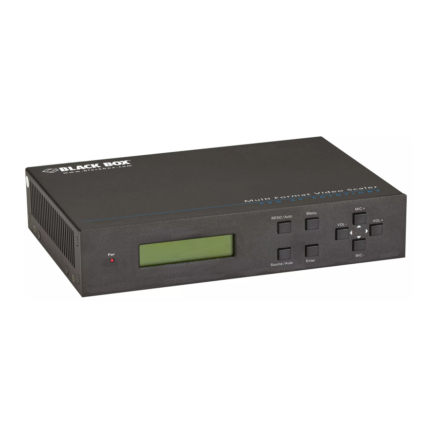
Multi-Format Video Scaler with Extension - 5-Port
User Manual
Scale and switch five video and six audio inputs
to HDMI and HDBaseT outputs up to 230 feet (70 meters).
Order toll-free in the U.S.: Call 877-877-BBOX (outside U.S. call 724-746-5500)
Customer
FREE technical support 24 hours a day, 7 days a week: Call 724-746-5500 or fax
Support
724-746-0746 • www.blackbox.com • info@blackbox.com
Information
AVS-5DA1-HDB
Advertisement
Table of Contents

Related Manuals for Black Box AVS-5DA1-HDB


Summary of Contents for Black Box AVS-5DA1-HDB
- Page 1 AVS-5DA1-HDB Multi-Format Video Scaler with Extension - 5-Port User Manual Scale and switch five video and six audio inputs to HDMI and HDBaseT outputs up to 230 feet (70 meters). Order toll-free in the U.S.: Call 877-877-BBOX (outside U.S. call 724-746-5500)
- Page 2 Trademarks Used in this Manual Trademarks Used in this Manual Black Box and the Double Diamond logo are registered trademarks of BB Technologies, Inc. Any other trademarks mentioned in this manual are acknowledged to be the property of the trademark owners.
- Page 3 FCC and IC RFI Statements/NOM Statement FEDERAL COMMUNICATIONS COMMISSION AND INDUSTRY CANADA RADIO FREQUENCY INTERFERENCE STATEMENTS This equipment generates, uses, and can radiate radio-frequency energy, and if not installed and used properly, that is, in strict accordance with the manufacturer’s instructions, may cause inter ference to radio communication. It has been tested and found to comply with the limits for a Class A computing device in accordance with the specifications in Subpart B of Part 15 of FCC rules, which are designed to provide reasonable protection against such interference...
- Page 4 NOM Statement 4. Todas las instrucciones de operación y uso deben ser seguidas. 5. El aparato eléctrico no deberá ser usado cerca del agua—por ejemplo, cerca de la tina de baño, lavabo, sótano mojado o cerca de una alberca, etc.. 6.
- Page 5 NOM Statement 16. El cable de corriente deberá ser desconectado del cuando el equipo no sea usado por un largo periodo de tiempo. 17. Cuidado debe ser tomado de tal manera que objectos liquidos no sean derramados sobre la cubierta u orificios de ventilación. 18.
-
Page 6: Safety Precautions
Safety Precautions Safety Precautions For best results, read all instructions carefully before using the transmitter. Save this manual for further reference. • Unpack the equipment carefully and save the original box and packing material for possible future shipment. • Follow basic safety precautions to reduce the risk of fire, electrical shock, and injury to persons. -
Page 7: Table Of Contents
Table of Contents Table of Contents 1. Specifications ......................8 2. Overview ......................11 2.1 Introduction ....................11 2.2 Features ....................... 11 2.3 What’s Included ..................12 2.4 Hardware Description ..................13 3. Installation ......................17 3.1 Usage Precautions ..................17 3.2 System Diagram ..................17 3.3 Connection Procedure .................17 3.4 Microphone Connection ................18 3.5 Applications ....................21... -
Page 8: Specifications
Chapter 1: Specifications 1. Specifications Video Input Video Input Connectors (3) HDMI female, (2) VGA (15-pin) female Video Input Signal HDMI, YPbPr, C-video, VGA Video Output Video Output (1) HDMI female, Connectors (1) RJ-45 HDBaseT Video Output Signal (1) HDMI, (1) HDBaseT IR Input Input (1) IR IN... - Page 9 Chapter 1: Specifications Audio Output Audio Output (1) stereo Audio Output Connector 3P captive (3.81-mm) Output Impedance 70 ohms Audio General Frequency Response 20 Hz to 20 kHz Stereo Channel >80 dB @1kHz Separation Distance Up to 230 ft. (70 m) User Controls IR remote, buttons, and RS-232 Pin Configuration...
- Page 10 Chapter 1: Specifications Dimensional Diagram Page 10 724-746-5500 | blackbox.com...
-
Page 11: Overview
Chapter 2: Overview 2. Overview 2.1 Introduction The Multi-Format Video Scaler with Extension - 5-Port (AVSC-5DA1-HDB) is a compact mini scaler switcher with 5 video inputs (3 HDMI, 2 VGA) and 6 audio inputs (3 HDMI audio and 2 VGA audio: switched following the video; 1 MIC audio input). The VGA input supports VGA, YPbPr, and C-video, so the scaler switcher works with multiple video signals. -
Page 12: What's Included
3. Click on the “Resources” tab on the product page, and select the document you wish to download. If you have any trouble accessing the Black Box site to download the manual, you can contact our Technical Support at 724-746-5500 or info@blackbox.com. -
Page 13: Hardware Description
Chapter 2: Overview 2.4 Hardware Description Figures 2-1 and 2-2 show the front and back panels of the scaler. Tables 2-1 and 2-2 describe the scaler's components. 7 8 9 Table 2-1. Front-panel components. Number in Component Description Figure 2-1 Power Lights red when power is on, turns green in standby indicator... - Page 14 Chapter 2: Overview Number in Component Description Figure 2-1 ENTER Confirm the selection in the menu. RESO/AUTO • Used as an output resolution manual switching button, select from 1920 x 1200, 1920 x 1080, 1600 x 1200, 1360 x 768, 1280 x 800, 1280 x 720, 1024 x 768.
- Page 15 Chapter 2: Overview Figure 2-2. Back panel. Table 2-2. Back panel components. Number in Component Description Figure 2-2 AUDIO INPUT Includes (3) HDMI audio and (2) VGA audio inputs. Users can choose any one audio type (embedded HDMI audio or external input audio) for HDMI audio input by sending RS-232 commands.
- Page 16 Chapter 2: Overview Table 2-2 (continued). Back panel components. Number in Component Description Figure 2-2 MIC port Connects to microphone. Dial switch Includes 3 levels: 48-V phantom power mode (con- nect with condenser microphone), MIC mode (connect with dynamic microphone), and LINE mode (connect with wireless microphone or line audio).
-
Page 17: Installation
Chapter 3: System Connection 3. System Connection 3.1 Usage Precautions 1. Install the system in a clean environment that has a proper temperature and humidity. 2. Make sure that all the power switches, plugs, sockets, and power cords are insulated and safe. -
Page 18: Microphone Connection
Chapter 3: System Connection Step 4. Connect an AVS-HDB-RX to the he AVSC-5DA1-HDB’s HDBaseT output port with twisted pair. Step 5. Connect a speaker, headphone, or amplifier to the AVSC-5DA1-HDB’s AUDIO OUTPUT port. Step 6. Connect a control device (e.g. PC) to the RS-232 port of the AVSC-5DA1-HDB or AVS-HDB-RX (bi-directional RS-232 control, either end is available). - Page 19 Chapter 3: System Connection Figure 3-2. 48-V phantom power input. MIC input MIC input has low frequency characteristics, and wide frequency response. When switched to “MIC,” the microphone input is used for connecting to a dynamic microphone. There are two different connection methods: 1.
- Page 20 Chapter 3: System Connection Figure 3-4. Mic input, balanced connection. LINE input LINE input has low frequency characteristics and wide frequency response. When switched to “LINE,” the microphone input is used to connect to line audio or wireless microphone output. There are two different connection methods: 1.
-
Page 21: Applications
Chapter 3: System Connection Figure 3-6. LINE input, balanced connection. 3.5 Application Use the AVSC-5DA1-HDB in various applications, including computer systems, monitor- ing, conference rooms, large screen displays, television, education, command and con- trol centers, and smart homes. Page 21 724-746-5500 | blackbox.com... -
Page 22: Operation
Chapter 4: Operation 4. Operation 4.1 Front-Panel Buttons Use the front-panel buttons to adjust output resolution, for switching, to update software, adjust volume, and for other menu operations. 4.1.1 Adjusting the Resolution Resolution can be adjusted automatically and manually. Press and hold the RESO/AUTO button for 7 seconds or more to switch between auto-adjusting/manual-adjusting mode. - Page 23 Chapter 4: Operation The display result will be shown for two seconds. Auto-switching Function Auto-switching mode follows these principles: • New input principle: Once it detects a new input signal, the AVSC-5DA1-HDB will switch to this new signal automatically. • Power reboot principle: AVSC-5DA1-HDB remembers the last displayed signal when rebooting.
-
Page 24: Adjusting The Volume
Chapter 4: Operation 4.1.3 Adjusting the Volume In the OSD menu, press VOL – to decrease line volume, VOL + to increase. In the OSD menu, press MIC – to decrease MIC volume, MIC + to increase. 4.1.4 OSD Menu Press the MENU button to enter in OSD menu and use the UP, DOWN, LEFT, RIGHT buttons to navigate, then press the ENTER button to confirm the selection. - Page 25 Chapter 4: Operation 1. Standby button: Press this button to enter/exit standby mode. 2. Input channel selection buttons: INPUT 1 is for HDMI1, INPUT 2 for HDMI2…INPUT 5 for VGA2. AUTO: Enable/disable auto-switching mode. 3. Volume adjustment buttons: MIC-/+: turn down/up MIC volume LINE-/+: turn down/up line volume MIC MUTE: mute/unmute MIC audio LINE MUTE: mute/unmute line audio...
- Page 26 Chapter 4: Operation 4.2.2 IR Operation The 5 IR OUT ports correspond to the 5 video inputs separately, and the IR signals are switched following the corresponding video source. 1. Control the AVSC-5DA1-HDB or far-end display device locally using the corresponding IR remote.
-
Page 27: Cec Operation
Chapter 4: Operation AVS-HDB-RX HDTV HDTV IR receiver IR transmitter IR remote Figure 4-4. Control local device locally with IR remote. 4.3 CEC Operation The AVSC-5DA1-HDB supports CEC, and it can be turned on/off by sending RS-232 commands or OSD menu options. The default setting is ON. Commands pertaining to CEC: “50686%”... - Page 28 Chapter 4: Operation Table 4-1. CEC and Standby. Situation Working Status CEC: on, Standby: on Press the STANDBY button on the IR remote, and AVSC- 5DA1-HDB enters standby mode, along with all HDMI source devices. Press the STANDBY button again on the IR remote, and the AVSC-5DA1-HDB exits standby mode and the HDMI source devices start working.
-
Page 29: Rs-232 Control
Chapter 4: Operation 4.4 RS-232 Control Operation RS-232 can be transmitted bi-directionally between AVSC-5DA1-HDB and AVS-HDB-RX, so you can control a third-party RS-232 device locally or control the AVSC-5DA1-HDB remotely. When you want to control a third party RS-232 device, set the baud rate of this device to 2400, 4800, 9600, 19200, 38400, 57600, or 115200. - Page 30 Chapter 4: Operation Figure 4-1. PuTTY configuration screen using serial. 2. No username or password is required. Just press enter. Set the COM number, baud rate, data bit, stop bit, and parity bit correctly so you can send commands in the Command Sending Area of the screen. NOTE: To control the AVS-HDB-WPTX via an RS-232 port, configure the communication protocol parameters as: Baud rate: 9600;...
-
Page 31: Rs-232 Communication Commands
Chapter 4: Operation 4.4.3 RS-232 Communication Commands Communication protocol: RS-232 Communication Protocol Baud rate: 9600 Data bit: 8 Stop bit: 1 Parity bit: none Table 4-2. RS-232 commands. Switch Commands Command Function Feedback Example 50701% Switch to HDMI 1 input Switch to HDMI 1 50702% Switch to HDMI 2 input... - Page 32 Chapter 4: Operation Table 4-2 (continued). RS-232 commands. Audio Commands (continued) Command Function Feedback Example 50720% Mute LINE audio and MIC audio LINE Mute MIC Mute 50721% Unmute LINE audio and MIC audio LINE Unmute MIC Unmute 50722% Mute MIC audio MIC Mute 50723% Unmute MIC audio...
- Page 33 Chapter 4: Operation Table 4-2 (continued). RS-232 commands. Resolution Commands Command Function Feedback Example 50619% Change the resolution to 1360 x Resolution: 1360 x 768 768 HD 50626% Change the resolution to 1024 x Resolution: 1024 x 768 768 XGA 50627% Change the resolution to 1280 x Resolution: 1280 x 720...
- Page 34 Chapter 4: Operation Table 4-2 (continued). RS-232 commands. Setup Commands (continued) Command Function Feedback Example 50615% Set SM audio mode Sound Mode: xx (xx= Standard/ Music/Movie/Sports/User) 50655% Freeze output image Freeze: enable 50656% Cancel the freezing of output Freeze: disable image 50646% Enable MIC Volume Icon display...
- Page 35 Chapter 4: Operation Table 4-2 (continued). RS-232 commands. Setup Commands (continued) Command Function Feedback Example 50767% Restore default EDID EDID: initial 50768% Bypass EDID data from output to EDID: bypass input 50769% Upload custom EDID data to the EDID: user switcher 50770% Inquire EDID status...
- Page 36 Chapter 4: Operation Table 4-2 (continued). RS-232 commands. Menu Commands Command Function Feedback Example 50609% OK for OSD selection Key: ok 50610% LEFT button Key: left 50611% RIGHT button Key: right 50612% UP button Key: up 50613% DOWN button Key: down 50616% MENU button (enter OSD) OSD: Enter...
- Page 37 Chapter 4: Operation Table 4-2 (continued). RS-232 commands. Inquire Commands (continued) Command Function Feedback Example 50783% Display function 50640% Check the color temperature Color Temperature: xx (xx = Cool/Medium/Warm/User.) 50651% Check Volume Icon display status Volume Icon: xxxx 50652% Check Digital audio output status Embedded Audio Output: enable/ disable 50712%...
- Page 38 Chapter 4: Operation Table 4-2 (continued). RS-232 commands. Adjustment Commands (continued) Command Function Feedback Example 50730% Turn off HDMI output HDMI power off 50731% Turn on HDMI output HDMI power on 50732% Turn off HDBT output HDBT power off 50733% Turn on HDBT output HDBT power on 50734%...
- Page 39 Chapter 4: Operation NOTES: 1. Screen output adjusting is available only when the screen output adjusting is on. Send command 50678% to turn this on. 2. CEC commands with a gray background are available only when CEC is on. 3. MIC precedence: In Mute mode, if the MIC noise detection is on, the device will unmute MIC automatically if the outer noise exceeds the noise detection limit.
-
Page 40: Control The Avsc-5Da1-Hdb Or Third-Party Device From The Local Unit
Chapter 4: Operation 4.4.4 Control AVSC-5DA1-HDB or a Third-Party Device Locally 1. Connect the AVSC-5DA1-HDB’s RS-232 port to the PC’s RS-232 port. 2. Send command 50787% (serial control mode 1, factory default) via RS-232 communication software. 3. Send the right command of AVSC-5DA1-HDB or other remote RS-232 device connected in the present system. -
Page 41: Control The Avsc-5Da1-Hdb From The Local Or Remote Unit
Chapter 4: Operation 4.4.5 Control AVSC-5DA1-HDB from Local or Remote • Control AVSC-5DA1-HDB locally. 1. Connect the AVSC-5DA1-HDB’s RS-232 port to the PC’s RS-232 port. 2. Send command 50788% via RS-232 communication software. 3. Send the right command to control AVSC-5DA1-HDB. Connect as below: Figure 4-9. -
Page 42: Osd Menu Operation
Chapter 4: Operation 4.5 OSD Menu Operation The AVSC-5DA1-HDB provides a powerful OSD operation menu that contains four parts: optional settings, image settings, audio settings, and system settings. Press the MENU button on front panel (or the MENU button on IR remote or send com- mand 50616%) to enter in OSD menu, so it can set values through the OSD menu. -
Page 43: Picture
Chapter 4: Operation For INPUT4 and INPUT5, to change to a new format signal: 1. Select a format through this menu (the signal format changes while the video source is still the same). 2. Switch off the present signal channel (e.g. switch to another channel). 3. -
Page 44: Sound
Chapter 4: Operation Picture mode: Includes Dynamic, Standard, Mild, and User. You can set the image con- trast and brightness only in User mode. Color Temperature: Includes Cool, Medium, Warm, and User. Set to Red, Green and Blue (RGB) only in User mode. Aspect Ratio: Includes Native, 4:3, 16:9, Zoom1, Zoom2, Just Scan, and Panorama. -
Page 45: Setup
Chapter 4: Operation EQ: Adjusts the sound balance. 4.5.4 Setup The Setup menu includes OSD Language, Restore Factory Default, Blending, HDMI CEC, OSD Duration, and version inquiry. Figure 4-14. Setup menu. OSD Language: Supports 14 languages, including English (default), Chinese, etc. Restore Factory Default: Restores settings to original system state. -
Page 46: Vga Converter Cable
Chapter 4: Operation 4.6 VGA Converter Cable Because a VGA source supports YPbPr and C-video source, the AVSC-5DA1-HDB includes two VGA converter cables that comply with these signals. To select these VGA signals as the input source, switch to channel INPUT 4 (or INPUT 5), and then set the signal type in OSD. - Page 47 Chapter 4: Operation 2. Via RS-232 commands: Send the 50682% (or 50685%) command to switch to a YPbPr1 (or YPbPr2) source. 3. Via IR remote and OSD: Press the MENU button on the IR remote to enter the OSD, then in OPTION setting menu, set “INPUT 4 Select”...
-
Page 48: Troubleshooting And Maintenance
Failed or loose connection. output end. The scaler is broken. Make sure the connection is good. Contact Black Box Technical Support at 724-746-5500 or info@ blackbox.com. POWER indicator doesn’t Power cord connection failed. Make sure the power work or does not cord connection is good. - Page 49 Type in correct RS-232 device by a control parameters. communication device (e.g. a PC) parameters. Broken RS-232 port. through the RS-232 Contact Black Box port. Technical Support at 724-746-5500 or info@blackbox.com. Cannot control the The front panel buttons are Send command 50605% device by the front-panel locked.
- Page 50 NOTES Page 50 724-746-5500 | blackbox.com...
- Page 51 NOTES Page 51 724-746-5500 | blackbox.com...
- Page 52 724-746-5500 or blackbox.com. About Black Box Black Box provides an extensive range of networking and infrastructure products. You’ll find everything from cabinets and racks and power and surge protection products to media converters and Ethernet switches all supported by free, live 24/7 Tech support available in 60 seconds or less.
Need help?
Do you have a question about the AVS-5DA1-HDB and is the answer not in the manual?
Questions and answers