Advertisement
Table of Contents
- 1 Table of Contents
- 2 Safety Instructions
- 3 Component Identification
- 4 Pre-Operation Check
- 5 Starting the Engine
- 6 Generator Use
- 7 Stopping the Engine
- 8 Maintenance
- 9 Transportation, Storage and Exercise
- 10 Troubleshooting
- 11 Specifications
- 12 Wiring Diagram
- 13 Warranty
- 14 Emission Control System
- Download this manual
See also:
Operator's Manual
Advertisement
Table of Contents

Related Manuals for Kipor IG3000E


Summary of Contents for Kipor IG3000E
- Page 2 PREFACE Thank you for purchasing a Kipor Generator. This manual covers the operation and preventive maintenance of the IG3000E generator with EPA and California Air Resources Board (CARB) certification if so designated. All information in this publication is based on the latest product information available at the time of printing.
- Page 3 Indicates a strong possibility of severe personal injury or death if instructions are not followed. Indicates a possibility of personal injury or equipment damage if instructions are not followed. NOTE Gives helpful information. If a problem should arise or if you have any questions about the generator, please consult an authorized dealer or service center.
-
Page 4: Table Of Contents
CONTENTS 1. SAFETY INSTRUCTIONS··················································································1 2. COMPONENT IDENTIFICATION·········································································3 3. PRE-OPERATION CHECK·················································································5 4. STARTING THE ENGINE ··················································································9 5. GENERATOR USE ························································································· 11 6. STOPPING THE ENGINE ················································································ 16 7. MAINTENANCE ····························································································· 17 8. TRANSPORTATION, STORAGE AND EXERCISE ················································ 20 9. TROUBLESHOOTING ···················································································· 21 10. -
Page 5: Safety Instructions
1. SAFETY INSTRUCTIONS ■ Our generators are designed to give safe and dependable service if operated according to these instructions. Read and understand the owner's manual before operating the generator. Failure to do so could result in personal injury or equipment damage. ■... - Page 6 To ensure safe operation: ■ Gasoline is extremely flammable and explosive under certain conditions. Refuel in a well ventilated area with the engine stopped. ■ Keep away from smoking materials, sparks and other sources of combustion when refueling the generator. Always refuel in a well-ventilated location.
-
Page 7: Component Identification
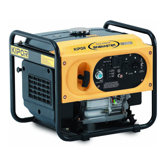
2. COMPONENT IDENTIFICATION 2.1 Outline drawing Fuel filler cap Frame Fuel Tank Choke knob Control panel Recoil starter handle Fuel gauge Spark plug Fuel valve Air filter Muffler Alternator Oil drain plug Oil fill... - Page 8 2.2 Control panel DC Receptacle Smart Throttle Switch 120V 30A Receptacle Status Indicator 120V 20A Receptacle Ignition Switch Circuit Protector Ground Terminal Overload Reset Switch AC output indication (green) Overload indication (red) Low oil level indication (red) 2.3 Serial Number Location: The serial number is stamped on the engine block to the left of the oil drain plug.
-
Page 9: Pre-Operation Check
3. PRE-OPERATION CHECK CAUTION ■ Check the generator on a level surface with the engine stopped. 3.1 Engine Oil NOTE ■ Using non detergent oil or 2-stroke engine oil could shorten the engine's service life. ■ Use a high-detergent, premium quality 4-stroke engine oil, certified to meet or exceed U.S. - Page 10 3.2 Fuel If the fuel level is low, refuel the fuel tank to the specified level.. After refueling, tighten the fuel filler cap securely. Use unleaded 87 octane regular grade gasoline only. WARNING ■ Never use an oil/gasoline mixture or old, dirty gasoline. Avoid getting dirt, dust or water in the fuel tank.
- Page 11 High altitude performance can be improved by installing a smaller diameter main fuel jet in the carburetor. If you always operate the generator at altitudes higher than 5,000 feet (1500M) above sea level, have your authorized KIPOR dealer perform these carburetor modifications.
- Page 12 Operation of the generator at an altitude lower than the carburetor is jetted for may result in reduced performance, overheating, and serious engine damage caused by an excessively lean air/fuel mixture. 3.5 Ambient Temperature Generator output generally declines 1% for every 10° F (5.5° C) above 85° F (29° C). The normal operating range of the generator is -20°...
-
Page 13: Starting The Engine
4. STARTING THE ENGINE ■When starting the generator after adding fuel for the first time or after long term storage or after running out of fuel, turn the fuel valve lever to the "ON" position and wait10 to 20 seconds before starting the engine. - Page 14 START CHOKE KNOB Pull towards you TOWARDS RECOIL START: Pull starter handle straight towards you ■ Do not allow the starter grip to snap back. Return it slowly by hand. ■ Do not let the starter rope rub against the generator body or the rope will wear out prematurely.
-
Page 15: Generator Use
5. GENERATOR USE ■To prevent electrical shock from faulty appliances, the generator should be grounded. Connect a length of heavy cable between the generator's ground terminal and an external ground source. ■Connections for standby power to a building's electrical system must be made by a qualified electrician and must comply with all applicable laws and electrical codes. - Page 16 5.1 AC power application 1. Start the engine and make sure the green output indicator light comes on. 2. Confirm that the appliance to be used is switched off then plug in the appliance. ■Be sure that all appliances are in good working order before connecting them to the generator.
- Page 17 5.3 SMART Throttle Engine speed is kept at idle automatically when the electrical load is disconnected and returns to the proper speed by the electrical load when the load is reconnected. The engine speed varies according to the amount of load applied to the generator. Placing the smart throttle in the on position is recommended to minimize fuel consumption and engine noise while in operation.
- Page 18 5.6 DC application The DC receptacle may be used for charging 12 volt automotive-type batteries only. It is not designed to operate DC motors. Output voltage is 15-30V. DC output will vary according to the position of the Smart throttle switch. 1.
- Page 19 The DC output is to be used to charge batteries only. Serious damage to the stator windings can occur if connected to a DC motor or transformer. 2. Start the generator. ■ The DC receptacle may be used while the AC power is in use. ■...
-
Page 20: Stopping The Engine
6. STOPPING THE ENGINE To stop the engine in an emergency, turn the engine switch to the OFF position. IN NORMAL USE: 1. Switch off connected loads and pull the plugs from the receptacles. 2. Turn the engine switch to the OFF position. 3. -
Page 21: Maintenance
If the engine must be run, make sure the area is well ventilated. The exhaust contains poisonous carbon monoxide gas. ■ Use genuine Kipor parts or their equivalent. The use of replacement parts which are not of equivalent quality may damage the generator. - Page 22 7.1 Changing Oil Drain the oil while the engine is warm to assure rapid and complete draining. (1) Remove the oil filler cap and oil drain plug to drain the oil. (2) Install the oil drain plug, and tighten it securely. (3) Refill with the recommended oil, and check the oil level.
- Page 23 7.3 Spark Plug Service RECOMMENDED SPARK PLUG: WR7DC To ensure proper engine operation, the spark plug must be properly gapped and free of deposits. 1 Remove the spark plug cap. 2 Clean any dirt from around the spark plug base. 3.
-
Page 24: Transportation, Storage And Exercise
8. TRANSPORTING, STORAGE & EXERCISE 8.1 Transporting When transporting the generator, turn the fuel valve lever OFF and keep the generator level to prevent fuel spillage. Fuel vapors or spilled fuel may ignite. Never transport the generator in a vehicle with gasoline in the tank. 8.2 Extended Storage 1. -
Page 25: Troubleshooting
9. TROUBLESHOOTING When the engine will not start: Is there fuel in the tank? Refuel the fuel tank Is the starting knob is on the "ON" position? Turn it to the "ON" position Is the fuel valve open? Open the fuel valve Is the enough oil in the engine? Add the recommended oil. - Page 26 Appliance does not operate: Is the output indicator light ON? Take the generator to an Is the overload authorized dealer. indicator light ON? Check the electricity Take the generator to an appliance or equipment for any authorized dealer. defects. ■ Replace the electrical appliance or equipment.
-
Page 27: Specifications
10. SPECIFICATIONS Model IG3000E Type Inverter Rated Voltage Frequency 60 HZ Maximum Output 3000W, 25A Rated Output 2800W, 23.3A DC Output 12V-5.0A Engine Model KG205GEXi Engine Type 4 stroke, overhead valve, single cylinder Displacement 12.0 cu in (196 cc) Compression Ratio 8.5:1... -
Page 28: Wiring Diagram
11. WIRING DIAGRAM... -
Page 29: Warranty
Kipor distributor will pay for shipping of the unit from the repair center to the designated distributor facility and the shipping of a replacement unit. Kipor or its distributor reserves the right to repair or replace these parts at its option. - Page 30 Kipor will pay for minor adjustments for a period of ninety days from the purchase date of the generator.
- Page 31 Manual. Kipor recommends that you retain all record/receipts covering maintenance on your engine, but Kipor Power Equipment cannot deny warranty claims based on a lack of receipts or for your failure to perform all scheduled maintenance. You may be denied warranty coverage if a part has failed due to abuse, neglect, improper maintenance, or unapproved applications.
- Page 32 B. Electrical switches Warranty Provisions 1. Claims Warranty claims shall be filed in accordance with the provisions of the Kipor warranty and policies established with the authorized repair center network. 2. Exclusions Warranty coverage shall be denied for failure of an emissions control system part caused by abuse, neglect, improper maintenance or application as described in the Kipor Generator Owner’s Manual.
- Page 33 2. As the SORE owner, you should however be aware that Kipor may deny your warranty coverage if your SORE or a part has failed due to abuse, neglect, improper maintenance or unapproved modifications.
-
Page 34: Emission Control System
3. A catalyst is built into the muffler to further treat the engine exhaust. 4. A secondary air injection valve adds combustion air to ignite unburned fuel in the exhaust. Contact your authorized Kipor service center to obtain the correct replacement parts and service on this system. - Page 35 IG3000E CARB Intake and Fuel system...
- Page 36 IG3000E Exhaust System Gasket Muffler Secondary Air Injection Valve Spark Arrestor...
Need help?
Do you have a question about the IG3000E and is the answer not in the manual?
Questions and answers