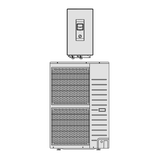
Panasonic WH-SXH09D0E8 Service Manual
Air-to-water heatpump indoor unit outdoor unit
Hide thumbs
Also See for WH-SXH09D0E8:
- Operating instructions manual (44 pages) ,
- Operating instructions manual (44 pages)
Table of Contents
Advertisement
Quick Links
This service information is designed for experienced repair technicians only and is not designed for use by the general public.
It does not contain warnings or cautions to advise non-technical individuals of potential dangers in attempting to service a product.
Products powered by electricity should be serviced or repaired only by experienced professional technicians. Any attempt to
service or repair the product or products dealt with in this service information by anyone else could result in serious injury or death.
In order to avoid frostbite, be assured of no refrigerant leakage during the installation or repairing of refrigerant circuit.
WH-SXH09D0E8
WARNING
PRECAUTION OF LOW TEMPERATURE
Indoor Unit
© Panasonic HA Air-Conditioning (M) Sdn. Bhd. 2011.
Unauthorized copying and distribution is a violation of law.
Order No. PHAAM1108115C2
Outdoor Unit
WH-UX09DN8
Advertisement
Table of Contents

Related Manuals for Panasonic WH-SXH09D0E8


Summary of Contents for Panasonic WH-SXH09D0E8
- Page 1 PRECAUTION OF LOW TEMPERATURE In order to avoid frostbite, be assured of no refrigerant leakage during the installation or repairing of refrigerant circuit. © Panasonic HA Air-Conditioning (M) Sdn. Bhd. 2011. Unauthorized copying and distribution is a violation of law.
-
Page 2: Table Of Contents
TABLE OF CONTENTS PAGE PAGE 16.3 Breakdown Self Diagnosis Function ... 44 1. Safety Precautions ..........3 16.4 Error Codes Table........45 2. Specifications .............5 16.5 Self-diagnosis Method ........ 47 17. Disassembly and Assembly Instructions ..76 3. Features...............7 17.1 To Remove Front Plate....... 76 4. -
Page 3: Safety Precautions
1. Safety Precautions Read the following “SAFETY PRECAUTIONS” carefully before perform any servicing. Electrical work must be installed or serviced by a licensed electrician. Be sure to use the correct rating and main circuit for the model installed. The caution items stated here must be followed because these important contents are related to safety. The meaning of each indication used is as below. - Page 4 WARNING 19. The unit is only for use in a closed portable water system. Utilization in an open water circuit or non-portable water circuit, may lead to excessive corrosion of the water piping and risk of incubating bacteria colonies, particularly Legionella, in water. 20.
-
Page 5: Specifications
2. Specifications Item Unit Outdoor Unit Performance Test Condition EN14511 Heating Capacity 9.00 BTU/h 30700 kcal/h 7740 4.74 kcal/hW 4.07 Noise Level dB (A) Power Level dB Air Flow /min (ft /min) 76.8 (2710) Refrigeration Control Device Expansion Valve Refrigeration Oil FV50S (1200) Refrigerant (R410A) kg (oz) - Page 6 Item Unit Power Factor Power factor means total figure of compressor and outdoor fan motor. Power Cord Number of core Length m (ft) Thermostat Electronic Control Protection Device Electronic Control Item Unit Indoor Unit Performance Test Condition EN14511 Operation Range Outdoor Ambient °C -20 ~ 35...
-
Page 7: Features
3. Features Inverter Technology - Energy saving High Efficiency Compact Design Environment Protection - Non-ozone depletion substances refrigerant (R410A) Long Installation Piping - Long piping up to 30 meter with height difference 20 meter - Flexible 4-way piping for outdoor unit Easy to use control panel Weekly Timer setting Quality Improvement... -
Page 8: Location Of Controls And Components
4. Location of Controls and Components Indoor Unit 4.1.1 Location of Control... - Page 11 4.1.2 Weekly Timer Setting...
-
Page 12: Outdoor Unit
4.1.3 Main Components Outdoor Unit... -
Page 13: Dimensions
5. Dimensions Indoor Unit... -
Page 14: Outdoor Unit
Outdoor Unit... -
Page 15: Refrigeration And Water Cycle Diagram
6. Refrigeration and Water Cycle Diagram Piping size Min. Max. Rated Common Additional Piping Piping Model Length Length Elevation Refrigerant Length Length Liquid (g/m) UX09DN8 5/8” 3/8” * If piping length is over common length, additional refrigerant should be added as shown in the table. -
Page 16: Block Diagram
7. Block Diagram... -
Page 17: Wiring Connection Diagram
8. Wiring Connection Diagram Indoor Unit... -
Page 18: Outdoor Unit
Outdoor Unit... -
Page 19: Electronic Circuit Diagram
9. Electronic Circuit Diagram Indoor Unit... -
Page 20: Outdoor Unit
Outdoor Unit... -
Page 21: Printed Circuit Board
10. Printed Circuit Board 10.1 Indoor Unit 10.1.1 Main Printed Circuit Board... -
Page 22: Outdoor Unit
10.2 Outdoor Unit 10.2.1 Main Printed Circuit Board... - Page 23 10.2.2 Noise Filter Printed Circuit Board...
-
Page 24: Installation Instruction
11. Installation Instruction 11.1 Select the Best Location Indoor Unit Rated Min. Max. Addi- Piping size Length Eleva- Piping Piping tional There should not be any heat source or steam tion Length Length Refrige- Model near the unit. rant Gas Liquid A place where air circulation in the room is good. -
Page 25: Indoor Unit
11.3 Indoor Unit 11.3.3 Indoor Unit Installation 11.3.1 How to Fix Installation Plate The mounting wall is strong and solid enough to 11.3.3.1 Install the Indoor Unit prevent it from vibration. Engage the slots on the indoor unit to the hooks of installation plate . - Page 26 Refer to Diagram 4.1 for pipe connection of Panel Heater, Floor Heater, and etc. Fail to connect the pipes appropriately might cause the unit malfunction. 11.3.3.4 Drain Hose Installation Use inner diameter 15 mm drain hose in the market. This hose must to be installed in a continuously Be sure to use two spanners to tighten the downward direction and in a frost-free connection.
- Page 27 To avoid cable and cord harmed by sharp edge, cable and cord must go through bushing (located at the bottom of indoor unit) before carry out electrical connection. The bushing must be used and must not take off. 11.3.4.1 Connecting Requirement The equipment’s power supply 1 complies with IEC/EN 61000-3-2.
-
Page 28: Outdoor Unit
11.4 Outdoor Unit 11.4.1 Install the Outdoor Unit After selecting the best location, start installation according to Indoor/Outdoor Unit Installation Diagram. Fix the unit on concrete or rigid frame firmly and horizontally by bolt nut (ø10 mm). When installing at roof, please consider strong wind and earthquake. -
Page 29: Connect The Cable To The Outdoor Unit
11.4.3 Evacuation of the Equipment WHEN INSTALLING AN AIR-TO-WATER HEATPUMP, BE SURE TO EVACUATE THE AIR INSIDE THE INDOOR UNIT AND PIPES in the following procedure. Connect a charging hose with a push pin to the Low side of a charging set and the service port of the 3- way valve. -
Page 30: Pipe Insulation
Secure the cable onto the control board with the holder (clamper). Select required direction and apply protective bushing provided in accessories to protect cables from sharp edges. Once all wiring work has been completed, tie the cable and cord together with the binding strap so that they do not touch other parts such as the compressor and bare copper pipes. -
Page 31: Operation And Control
12. Operation and Control 12.1 Basic Function Inverter control, which equipped with a microcomputer in determining the most suitable operating mode as time passes, automatically adjusts output power for maximum comfort always. In order to achieve the suitable operating mode, the microcomputer maintains the set temperature by measuring the temperature of the environment and performing temperature shifting. - Page 32 12.1.3 Water Temperature Thermo Shift Setting Switchs are ignored during “PUMPDW” = ON. Switchs are ignored during “STATUS” = ON. ▲ ▼ “ ”, “ ”, “SELECT” switch are ignored if “SETTING” = OFF. “CANCEL” switch is ignored if “SETTING” = OFF & “STATUS” = OFF. If “SET”...
-
Page 33: Water Pump
12.2 Water Pump 12.2.1 Water Pump Control Once the indoor unit is ON, the water pump will be ON immediately and no error judgement for 9 minutes. However, during this 9 minutes operation, if there is any abnormality cause at outdoor or malfunction, the compressor should be OFF immediately and restart delay after 3 minutes. -
Page 34: Indoor Unit Safety
12.5 Indoor Unit Safety 12.5.1 Indoor Unit Safety Control When water pump is ON, the system will start checking flow switch status (ON/OFF). If the flow switch ON for 10 seconds, the system will check on the water inlet temperature for 10 seconds. If the water inlet temperature not exceeds 80°C, the water pump shall be continuously running with normal mode. -
Page 35: Indication Panel
12.7 Indication Panel Operation Color Green Light ON Operation ON Light OFF Operation OFF Note: If Operation LED is blinking, there is an abnormality operation occurs. 12.8 Quiet Operation Purpose: - To provide quiet operation compare to normal operation by reduces outdoor unit noise. Starting condition: When quiet button is presses. -
Page 36: Protection Control
13. Protection Control 13.1 Protection Control for All Operations 13.1.1 Time Delay Safety Control The compressor will not start for three minutes after stop of operation. 13.1.2 30 Seconds Forced Operation Once the compressor starts operation, it will not stop its operation for 30 seconds. However, it can be stopped using control panel at indoor unit. -
Page 37: Low Pressure Protection Control
13.1.6 High Pressure Sensor Control Purpose: - To protect the system operation. Detection period: - After compressor on for 1 minute. Detection conditions: - When abnormal high voltage detection, 5V or when open circuit detection 0V for 5 seconds continuously. After detection: - When abnormality is detected continue 5 seconds, unit stop operation. -
Page 38: Protection Control For Heating Operation
13.1.10 Extreme Low Temperature Control Purpose: - To improve the compressor reliability during cold start and after deice when running in extreme low outdoor temperature. Starting condition: Heating operation Outdoor air temperature < -10°C Actual frequency ≥ 50Hz Compressor discharge temperature < 20°C When the above condition is fulfilled, this control is activated. -
Page 39: Servicing Mode
14. Servicing Mode 14.1 Test Run Fill up the boiler tank with water. For details refer to boiler tanks installation instruction and operation instruction. Set ON to the indoor unit and RCCB. Then, for control panel’s operation please refers to air-to-water heatpump’s operation instruction. -
Page 40: Maintenance Guide
15. Maintenance Guide In order to ensure optimal performance of the unit, checks and inspections on the unit and the field wiring must be carried out regularly. Please request a licensed technician for carry out maintenance job. Before carried out any maintenance or repair work, and removing the front plate of heat exchanger unit, always switch off all power supply (i.e. - Page 41 External water filter (field supply) Clean the external water filter in regularly basic. External water filter is located inside the tube connector which is before water inlet connector of indoor unit (indicated with “WATER IN”). (Refer to figure below) Use spanner to detach the tube connector nut. Take out the filter carefully so that not deforms it shape.
-
Page 42: Troubleshooting Guide
16. Troubleshooting Guide 16.1 Refrigeration Cycle System In order to diagnose malfunctions, make sure that there are no electrical problems before inspecting the refrigeration cycle. Such problems include insufficient insulation, problem with the power source, malfunction of a compressor and a fan. -
Page 43: Relationship Between The Condition Of The Air-To-Water Heatpump Indoor And Outdoor Units And Pressure And Electric Current
16.2 Relationship between the Condition of the Air-to-Water Heatpump Indoor and Outdoor Units and Pressure and Electric Current Heating Mode Condition of the Air-to-Water Heatpump indoor and outdoor Low Pressure High Pressure Electric current during operation units Water leakage or insufficient water flow rate in the system Excessive amount of refrigerant Inefficient compression... -
Page 44: Breakdown Self Diagnosis Function
16.3 Breakdown Self Diagnosis Function 16.3.1 Self Diagnosis Function (Three Digits Alphanumeric Code) When abnormality occur during operation, the system will stop operation, and OFF/ON control panel LED will blink and error code will display on the control panel timer display LCD. Even error code is reset by turning OFF power supply or by pressing ERROR RESET button, if the system abnormality is still un-repaired, system will again stop operation, and OFF/ON control panel LED will again blink. -
Page 45: Error Codes Table
16.4 Error Codes Table Diagnosis display Abnormality/Protection control Abnormality judgement Primary location to verify No abnormality detected — — Indoor/Outdoor capacity unmatched 90s after power supply Indoor/outdoor connection wire Indoor/outdoor PCB Specification and combination table in catalogue Outdoor compressor temperature sensor Continue for 5 sec. - Page 46 Diagnosis display Abnormality/Protection control Abnormality judgement Primary location to verify Outdoor Current Transformer open — Insufficient refrigerant circuit Outdoor PCB Compressor low Outdoor EVA outlet temperature sensor Continue for 5 sec. Outdoor EVA outlet temperature sensor abnormality (defective or disconnected) Outdoor bypass outlet temperature Continue for 5 sec.
-
Page 47: Self-Diagnosis Method
16.5 Self-diagnosis Method 16.5.1 Connection Capability Rank Abnormality (H12) Malfunction Decision Conditions: During startup operation of cooling and heating, the capability rank of indoor checked by the outdoor is used to determine connection capability rank abnormality. Malfunction Caused: Wrong model interconnected. Wrong indoor unit or outdoor unit PCB (main) used. - Page 48 16.5.2 Compressor Tank Temperature Sensor Abnormality (H15) Malfunction Decision Conditions: During startup and operation of cooling and heating, the temperatures detected by the compressor tank temperature sensor are used to determine sensor error. Malfunction Caused: Faulty connector connection. Faulty sensor. Faulty outdoor unit PCB (main).
- Page 49 16.5.3 Indoor Refrigerant Liquid Temperature Sensor Abnormality (H23) Malfunction Decision Conditions: During startup and operation of cooling and heating, the temperatures detected by the indoor refrigerant liquid temperature sensor are used to determine sensor error. Malfunction Caused: Faulty connector connection. Faulty sensor.
- Page 50 16.5.4 Compressor Low Pressure Protection (H42) Malfunction Decision Conditions: During operation of heating and after 5 minutes compressor ON, when outdoor pipe temperature below -29°C or above 26°C is detected by the outdoor pipe temperature sensor. Malfunction Caused: Dust accumulation on the outdoor unit heat exchanger. Air short circuit at outdoor unit.
- Page 51 16.5.5 Water Flow Switch Abnormality (H62) Malfunction Decision Conditions: During operation of cooling and heating, the water flow detected by the indoor water flow switch is used to determine water flow error. Malfunction Caused: Faulty water pump. Water leak in system. Faulty connector connection.
- Page 52 16.5.6 Outdoor High Pressure Abnormality (H64) Malfunction Decision Conditions: During operation of cooling and heating, when the outdoor high pressure sensor output signal is 0Vdc or 5Vdc. Malfunction Caused: Faulty connector connection. Faulty sensor. Faulty outdoor unit PCB (main). Abnormality Judgment: Continue 4 times in 20 minutes.
- Page 53 16.5.7 Indoor-Control Panel Communication Abnormality (H76) Malfunction Decision Conditions: During standby and operation of cooling and heating, indoor-control panel error occur. Malfunction Caused: Faulty connector connection. Faulty control panel. Faulty indoor unit PCB (main).
- Page 54 16.5.8 Indoor/Outdoor Abnormal Communication (H90) Malfunction Decision Conditions: During operation of cooling and heating, the data received from outdoor unit in indoor unit signal transmission is checked whether it is normal. Malfunction Caused: Faulty outdoor unit PCB (main). Faulty indoor unit PCB (main). Indoor-outdoor signal transmission error due to wrong wiring.
- Page 55 16.5.9 Unspecified Voltage between Indoor and Outdoor (H95) Malfunction Decision Conditions: The supply power is detected for its requirement by the indoor/outdoor transmission. Malfunction Caused: Insufficient power supply. Faulty outdoor unit PCB (noise filter/main).
- Page 56 16.5.10 Outdoor High Pressure Protection (H98) Malfunction Decision Conditions: During operation of heating, when pressure 4.0MPa and above is detected by outdoor high pressure sensor. Malfunction Caused: Faulty water pump. Insufficient water flow rate in system. Water leak in system. 2/3 way closed.
- Page 57 16.5.11 Indoor Freeze-up Protection (H99) Malfunction Decision Conditions: During anti-freezing control in cooling operation, when the indoor refrigerant liquid temperature < 0°C. Malfunction Caused: Faulty water pump. Insufficient water flow rate in system. Water leak in system. 2 way valve partially closed. Clogged expansion valve or strainer.
- Page 58 16.5.12 Outdoor High Pressure Switch Activate (F12) Malfunction Decision Conditions: During operation of cooling and heating, when pressure 4.5MPa and above is detected by outdoor high pressure switch. Malfunction Caused: Dust accumulation on the outdoor unit heat exchanger. Air short circuit at outdoor unit. Faulty water pump.
- Page 59 16.5.13 Compressor Rotation Failure (F14) Malfunction Decision Conditions: A compressor rotation failure is detected by checking the compressor running condition through the position detection circuit. Malfunction Caused: Compressor terminal disconnect. Faulty outdoor unit PCB (main). Faulty compressor. Abnormality Judgment: Continue 4 times in 20 minutes.
- Page 60 16.5.14 Outdoor Fan Motor (DC Motor) Mechanism Locked (F15) Malfunction Decision Conditions: The rotation speed detected by the Hall IC of the fan motor during fan motor operation is used to determine abnormal fan motor (feedback of rotation > 2550rpm or < 50rpm). Malfunction Caused: Operation stop due to short circuit inside the fan motor winding.
- Page 61 16.5.15 Input Over Current Detection (F16) Malfunction Decision Conditions: During operation of cooling and heating, when outdoor current above 10.6A is detected by the current transformer (CT) in the outdoor unit PCB. Malfunction Caused: Excessive refrigerant. Faulty outdoor unit PCB (main). Abnormality Judgment: Continue 3 times in 20 minutes.
- Page 62 16.5.16 Compressor Overheating (F20) Malfunction Decision Conditions: During operation of cooling and heating, when temperature above 112°C is detected by the compressor tank temperature sensor. Malfunction Caused: Faulty compressor tank temperature sensor. 2/3 way valve closed. Refrigerant shortage (refrigerant leakage). Clogged expansion valve or strainer.
- Page 63 16.5.17 IPM Overheating (F22) Malfunction Decision Conditions: During operation of cooling and heating, when temperature 95°C is detected by the outdoor IPM temperature sensor. Malfunction Caused: Faulty outdoor unit fan motor. Faulty outdoor unit PCB (main). Abnormality Judgment: Continue 4 times in 30 minutes.
- Page 64 16.5.18 Output Over Current Detection (F23) Malfunction Decision Conditions: During operation of cooling and heating, when outdoor DC current is above 33.4 ± 5.0A is detected by the IPM DC Peak sensing circuitry in the outdoor unit PCB (main). Malfunction Caused: Faulty outdoor unit PCB (main).
- Page 65 16.5.19 Refrigeration Cycle Abnormality (F24) Malfunction Decision Conditions: During operation of cooling and heating, compressor frequency > Frated. During operation of cooling and heating, running current: 0.65A < I < 1.65A. During operation of cooling, water inlet temperature - indoor refrigerant liquid temperature < 5°C. During operation of heating, indoor refrigerant liquid temperature - water inlet temperature <...
- Page 66 16.5.20 Four Way Valve Abnormality (F25) Malfunction Decision Conditions: During heating operation, when the indoor pipe temperature of thermostat ON indoor unit < 0°C. During cooling operation, when the indoor pipe temperature of thermostat ON indoor unit > 45°C. Malfunction Caused: Faulty sensor.
- Page 67 16.5.21 Outdoor High Pressure Switch Abnormal (F27) Malfunction Decision Conditions: During compressor stop, and outdoor high pressure switch is remain opened. Malfunction Caused: Faulty connector connection. Faulty switch. Faulty outdoor unit PCB (main). Abnormality Judgment: Continue for 1 minute.
- Page 68 16.5.22 Outdoor Air Temperature Sensor Abnormality (F36) Malfunction Decision Conditions: During startup and operation of cooling and heating, the temperatures detected by the outdoor air temperature sensor are used to determine sensor error. Malfunction Caused: Faulty connector connection. Faulty sensor. Faulty outdoor unit PCB (main).
- Page 69 16.5.23 Indoor Water Inlet Temperature Sensor Abnormality (F37) Malfunction Decision Conditions: During startup and operation of cooling and heating, the temperatures detected by the indoor water inlet temperature sensor are used to determine sensor error. Malfunction Caused: Faulty connector connection. Faulty sensor.
- Page 70 16.5.24 Outdoor Discharge Pipe Temperature Sensor Abnormality (F40) Malfunction Decision Conditions: During startup and operation of cooling and heating, the temperatures detected by the outdoor discharge pipe temperature sensor are used to determine sensor error. Malfunction Caused: Faulty connector connection. Faulty sensor.
- Page 71 16.5.25 Power Factor Correction (PFC) Abnormality (F41) Malfunction Decision Conditions: During operation of cooling and heating, when the PFC protection circuitry in the outdoor unit PCB (main) senses abnormal high DC voltage level. Malfunction Caused: Power supply surge. Compressor windings not uniform. Faulty outdoor unit PCB (main).
- Page 72 16.5.26 Outdoor Pipe Temperature Sensor Abnormality (F42) Malfunction Decision Conditions: During startup and operation of cooling and heating, the temperatures detected by the outdoor pipe temperature sensor are used to determine sensor error. Malfunction Caused: Faulty connector connection. Faulty sensor. Faulty outdoor unit PCB (main).
- Page 73 16.5.27 Outdoor Defrost Temperature Sensor Abnormality (F43) Malfunction Decision Conditions: During startup and operation of cooling and heating, the temperatures detected by the outdoor defrost temperature sensor are used to determine sensor error. Malfunction Caused: Faulty connector connection. Faulty sensor. Faulty outdoor unit PCB (main).
- Page 74 16.5.28 Indoor Water Outlet Temperature Sensor Abnormality (F45) Malfunction Decision Conditions: During startup and operation of cooling and heating, the temperatures detected by the indoor water outlet temperature sensor are used to determine sensor errors. Malfunction Caused: Faulty connector connection. Faulty sensor.
- Page 75 16.5.29 Outdoor Current Transformer Open Circuit (F46) Malfunction Decision Conditions: A current transformer (CT) open circuit is detected by checking the compressor running frequency ( rated frequency) and CT detected input current (< 0.65A) for continuously 20 seconds. Malfunction Caused: CT defective.
-
Page 76: Disassembly And Assembly Instructions
17. Disassembly and Assembly Instructions WARNING High Voltage are generated in the electrical parts area by the capacitor. Ensure that the capacitor has discharged sufficiently before proceeding with repair work. Failure to heed this caution may result in electric shocks. 17.1 To Remove Front Plate Please follow the steps below for take out front plate. -
Page 77: To Remove Pressure Gauge
17.3 To Remove Pressure Gauge 17.4 To Remove Control Panel... -
Page 78: To Remove Rccb
17.5 To Remove RCCB 17.6 To Remove Transformer and Electronic Controller Board... -
Page 79: To Remove Pressure Relief Valve, Flow Switch, Water Pump And Bottle Complete
17.7 To Remove Pressure Relief Valve, Flow Switch, Water Pump and Bottle Complete When reinstall the water pipe, use grease or water at the joining. - Page 80 When reinstall the water pipe, use grease or water at the joining.
-
Page 81: Technical Data
18. Technical Data 18.1 Operation Characteristics Heating Characteristics at Different Outdoor Air Temperature Condition Outdoor air temperature : 7°C (DBT), 6°C (WBT) Indoor water inlet temperature : 30°C Indoor water outlet temperature : 35°C Piping length : 7m 14.000 13.000 12.000 11.000 10.000... - Page 82 Heating Characteristics at Different Piping Length Condition Outdoor air temperature : 7°C (DBT), 6°C (WBT) Indoor water inlet temperature : 30°C Indoor water outlet temperature : 35°C 9.200 8.700 8.200 7.700 7.200 Piping Length (m) 2.000 1.950 1.900 1.850 1.800 Piping Length (m)
-
Page 83: Heating Capacity Table
18.2 Heating Capacity Table Tamb 9.00 3.28 9.00 3.55 9.00 3.95 9.00 4.34 9.00 4.77 9.00 5.20 9.00 2.75 9.00 3.20 9.00 3.66 9.00 4.11 9.00 4.31 9.00 4.50 9.00 2.40 9.00 2.55 9.00 2.82 9.00 3.09 9.00 3.60 9.00 4.11 9.00 1.68... -
Page 84: Exploded View And Replacement Parts List
19. Exploded View and Replacement Parts List 19.1 Indoor Unit Note: The above exploded view is for the purpose of parts disassembly and replacement. The non-numbered parts are not kept as standard service parts. - Page 85 <Model: WH-SXH09D0E8 > REF. NO. DESCRIPTION & NAME QTY. WH-SXH09D0E8 REMARKS BASE PAN CWD521266 HOT WATER COIL-COMPLETE CWB90C1051 FLOAT (FLOW SWITCH) CWB601008 FLARE NUT (3/8) CWT251061 FLARE NUT (5/8) CWT251064 PUMP CWB532096 PACKING (O-RING) I.D 32mm CWB811082 PACKING (O-RING) I.D 13.8mm...
-
Page 86: Outdoor Unit
19.2 Outdoor Unit... - Page 88 Note: The above exploded view is for the purpose of parts disassembly and replacement. The non-numbered parts are not kept as standard service parts.
- Page 89 <Model: WH-UX09DN8 > REF. NO. DESCRIPTION & NAME QTY. WH-UX09DN8 REMARKS BASE PAN ASS’Y CWD52K1225 COMPRESSOR 5JD420XBA22 ANTI-VIBRATION BUSHING CWH50055 NUT FOR COMP. MOUNT. CWH561049 PACKING CWB811017 CRANKCASE HEATER CWA341053 CONDENSER COMPLETE CWB32C2983 HIGH PRESSURE SENSOR CWA50C2570 DISCHARGE MUFFLER CWB121014 PRESSURE SWITCH CWA101013 3-WAYS VALVE (GAS)
- Page 90 REF. NO. DESCRIPTION & NAME QTY. WH-UX09DN8 REMARKS EXPANSION VALVE CWB051029 CRANKCASE HEATER (BASE PAN) CWA341061 ELECTRO MAGNETIC SWITCH K6C2AGA00002 ELECTRO MAGNETIC SWITCH K6C4E8A00001 REACTOR G0C153J00009 PTC THERMISTORS D4DDG1010001 CAPACITOR-FM DS441205NPQA Note: All parts are supplied from PHAAM, Malaysia (Vendor Code: 00029488). “O”...
Need help?
Do you have a question about the WH-SXH09D0E8 and is the answer not in the manual?
Questions and answers