Table of Contents
Advertisement
Quick Links
IMPORTANT:
THESE INSTRUCTIONS ARE TO
REMAIN WITH THE HOMEOWNER
SAVE THESE INSTRUCTIONS
SAFETY NOTICE
If this stove is not properly installed, a house
fi re may result. For your safety, follow the
installation directions. Consult local building
or officials about restrictions and installation
inspection requirements in your area.
TESTED and LISTED
to ULC S628 / UL 1482
Meets the U.S. Environmental Protection
Agency's July 1990 Particulate Emission
Standards
190112-24
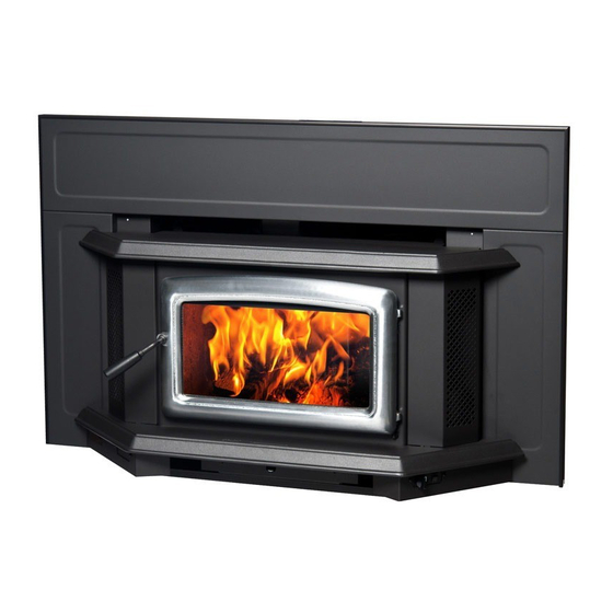
Summit
Wood Insert
INSTALLATION
AND OPERATING
INSTRUCTIONS
MODEL:
SUMMIT INSERT
SERIES - B
SINB.BODY
SERIAL #
5055.5112
Advertisement
Table of Contents

Related Manuals for Pacific energy SUMMIT INSERT SERIES - B


Summary of Contents for Pacific energy SUMMIT INSERT SERIES - B
- Page 1 IMPORTANT: THESE INSTRUCTIONS ARE TO REMAIN WITH THE HOMEOWNER SAVE THESE INSTRUCTIONS SERIAL # SAFETY NOTICE If this stove is not properly installed, a house fi re may result. For your safety, follow the installation directions. Consult local building or officials about restrictions and installation inspection requirements in your area.
-
Page 2: Table Of Contents
Contents Safety .................... 3 Clearances ................... 3 NOTE: Masonry or Factory Built Fireplace ............3 WE STRONGLY Mantel Clearances ................. 5 Dimensions .................. 5 R E C O M M E N D T H AT Installation ..................6 SMOKE DETECTORS BE Fireplace Specifi cations ................. -
Page 3: Safety
Safety Clearances Masonry or Factory Built Fireplace Please read this entire manual before installation and use of this wood burning insert. Failure to follow The minimum required clearances to surrounding combus- tible materials when installed into a masonry or factory built these instructions could result in property damage, fi replace are listed below and in fi gure #1. - Page 4 Fireplace hearth requirements: (Measured without the insert) The non-combustible fi replace hearth must be raised 3” above an adjacent combustible fl oor and extend 16” in front and 8” beyond each side of the existing fi replace opening. A non-combustible hearth that extends a minimum 20-1/2” in front of the fi replace opening may be fl ush to an adjacent combustible fl oor.
-
Page 5: Mantel Clearances
Dimensions 6 5/8” 9 1/8” 22 15/16” 21” 10 7/8” 18” 27 9/16” 25 3/8” 28 7/8” 12 1/4” SURROUND DIMENSIONS REG. SURROUND O/S SURROUND 48 3/4” 52 3/4" 32 1/16” 34 1/16" 23 5/16” 40 7/8” Mantel Clearances MANTEL CLEARANCE 12"... -
Page 6: Installation
Installation Full Flue Liner Fig. # 2 Your Insert is designed to be installed into a masonry or fac- tory built zero-clearance fi replace. The masonry fi replace Rain Cap must be built according to the requirements of the Standard of Chimneys, Fireplaces, Vents and Solid Fuel Burning ap- pliances, N.F.P.A. -
Page 7: Full Flue Liner - (Required In Canada)
Full Flue Liner - (Required in Canada) 1) Measure the chimney height from the top of the existing fl ue to the fl oor of the hearth. This will allow extra length of liner for fl ashing and rain cap. 2) Feed the stainless steel liner from top of the chimney, through the damper area and into the fi replace cavity. -
Page 8: Into A Factory Built Fireplace
Into a Factory Built Fireplace Your Insert may be installed into a factory built fi replace (size permitting) with the following requirements: 1) Inspect your fi replace for damage or other physical de- fects. The fi replace must be in good working condition. If in doubt about its condition, seek professional advice. -
Page 9: Surround Assembly And Installation
Surround Assembly and Installation Fig. # 9 Fig. # 7 1) Lay part A, B and C face down on a fl at, non-marring surface. Fasten together with 1/4" x 1/2" bolts and nuts Part F provided through holes at points “D” (Fig. #8 and #10). 2) Lift the surround assembly to the upright position and make sure the front face is fl at and even at the joints. - Page 10 10) Slide the pre-assembled surround behind the ash lip. 7) Remove wing screws on each side of the Bay top and set Ensure that the electric supply cord is located in the slots Bay top aside to prevent damage. (Fig. #12). in the base of the surround.
-
Page 11: Fan Speed Controller Relocation
Fan Speed Controller Relocation 4) Loosen the two bolts that secure the ash lip to the fi rebox, carefully lift up the ash lip and remove from the fi rebox and unscrew the wire support tabs. The fan speed controller is factory installed under the ash lip on the right hand side. - Page 12 7) Route cable from speed control to fan and reattach wire 8) Remove Thermal switch from right hand fan mounting support tabs on the underside of the ash lip. Note wire bracket and relocate to left hand fan mounting bracket. positions.
-
Page 13: Operation
Operation tion, windows, climate, etc.), the proper setting can only be found by trial and error and should be noted for future burns. 2) To refuel, adjust air control to "H" (high) position (pushed Wood Selection to the far left) and give the fi re time to brighten. Open door slowly, this will prevent backpuffing. -
Page 14: More Wood, More Heat
More Wood, More Heat Blower Seasoned wood has approximately 7500 BTU’s per pound. If you put 10 pounds of wood in your stove for an eight hour burn the wood will be producing 9375 BTU’s per hour. (7500 The Insert comes equipped with twin variable speed cir- BTU x 10 lbs / 8 hrs. -
Page 15: Creosote
In Case of a Chimney Fire Creosote 1. Prepare to evacuate to ensure everyone’s safety. Have a well understood plan of action for evacuation. Have a Formation and Need for Removal place outside where everyone is to meet. 2. Close air inlets on stove. When wood is burned slowly, it produces tar and other or- ganic vapours, which combine with expelled moisture to form 3. -
Page 16: Maintenance
Maintenance Do not store wood within heater installation clearances, or within the space required for fuel loading and ash removal. Keep the area around the heater clean and free of all loose Burn wood only, dry and well seasoned. The denser or combustibles, furniture, newspapers, etc. -
Page 17: Understanding & Operating Your Pacifi C Energy Stove
(smoke). 5 to 10 minutes more Pacific Energy has and then set the air designed a system that control to the desired solves the problem by position. -
Page 18: Troubleshooting
Troubleshooting Problem Cause Cure Glass is Dirty 1. Wood is wet - Use dry wood 2. Turning down air control - Do not turn down until or damper too soon a) there is a good bed of coals b) the wood is charred 3. -
Page 19: Firebrick Installation
Firebrick Installation Summit Insert Wood Stove This package contains 17 full-size fi rebricks, as well as 7 various cut-size bricks. With the woodstove in the upright position, install fi rebricks as follows: 1) Place the fi rebricks on the bottom of the unit fi rst. Use 7 full-size (D) and 3 cut bricks (C &... -
Page 20: Replacement Parts
Replacement Parts (WHEN ORDERING, INCLUDE PART NUMBER WITH DESCRIPTION) ITEM DESCRIPTION PART NO. ITEM DESCRIPTION PART NO. 1..Bay Top (c/w Washers and Nuts) ....SINS.50374524 23..Door Handle Assembly (c/w Wood Handle and Nut) ....2..Casing Top, Back ............. 3502 WODC.4147C 3..Casing Top, Front ............ - Page 21 Fig. # 32 SINB.BODY 190112-24...
- Page 22 NOTES: SINB.BODY 190112-24...
-
Page 23: Label
MODEL / MODÈLE: SUMMIT INSERT SERIES / SÉRIE: B INSTALL AND USE ONLY IN ACCORDANCE WITH PACIFIC ENERGY’S INSTALLATION AND OPERATING INSTRUCTIONS. CONTACT LOCAL BUILDING OR FIRE OFFICIALS ABOUT CODES, RESTRICTIONS AND INSTALLATION INSPECTION IN YOUR AREA. INSTALL AND USE ONLY IN MASONRY OR FACTORY BUILT FIREPLACE. DO NOT CONNECT THIS UNIT TO A CHIMNEY FLUE SERVING ANOTHER APPLIANCE. - Page 24 PACIFIC ENERGY FIREPLACE PRODUCTS LTD. Technical Support: 1-250-748-1184 www.pacifi cenergy.net 2975 Allenby Rd., Duncan, B.C. V9L 6V8 Printed in Canada...
Need help?
Do you have a question about the SUMMIT INSERT SERIES - B and is the answer not in the manual?
Questions and answers