
Related Manuals for Tennant 3640


Summary of Contents for Tennant 3640
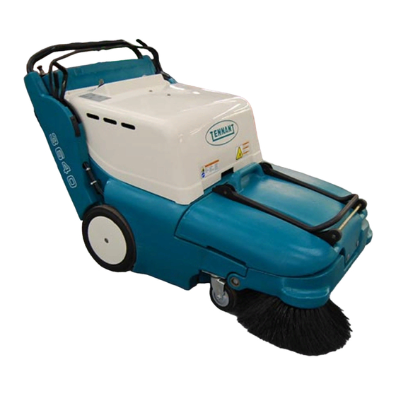
- Page 1 3640 (Gas/LPG) Sweeper Operator Manual North America / International 330580 Rev. 06 (02-2008) *330580* www.tennantco.com...
- Page 2 Engine exhaust from this product contains chemicals known to the State of California to cause cancer, birth defects, or other reproductive harm. Specifications and parts are subject to change without notice. Original instructions, Copyright E 2000, 2001, 2002, 2003, 2004, 2005, 2006, 2008 TENNANT Company, Printed in U.S.A.
-
Page 3: Table Of Contents
......SPARKPLUG ..... . 3640 330580 (12- -00) - Page 4 CONTENTS 3640 330580 (12- -00)
-
Page 5: Safety Precautions
Severe respiratory damage or - - Avoid contact with battery acid. asphyxiation can result. Provide - - Use Tennant supplied or equivalent adequate ventilation. Consult with your replacement parts. regulatory agency for exposure limits. Keep engine properly tuned. - Page 6 TOXIC GASES LABEL - - LOCATED ON THE CONTROL PANEL ON THE CONTROL PANEL BACK STRAIN LABEL - - LOCATED ON THE ENGINE COMPARTMENT COVER FLYING DEBRIS WARNING LABEL - - LOCATED ON THE MOTOR COMPARTMENT COVER 350841 3640 330580 (01- -00)
-
Page 7: Operation
AN LPG TANK section of this manual. 07324 - Fill the gas tank. FOR SAFETY: When servicing machine, keep flames and sparks away from fuel system service area. Keep area well ventilated. - Check the engine oil. 3640 330580 (01- -00) - Page 8 Tennant representative. - Order parts and supplies directly from your authorized Tennant representative. Use the parts manual provided when ordering parts. - After the first 50 hours of operation, follow the recommended procedures stated in the MAINTENANCE CHART.
-
Page 9: Machine Components
OPERATION MACHINE COMPONENTS 350659 A. Debris hopper B. Vacuum wand (option) C. Filter compartment D. Main brush E. Side brush F. Accessory bin G. Engine compartment H. Vac wand extension (option) 3640 330580 (01- -00) -
Page 10: Symbol Definitions
Side brush(es) down and on Side brush(es) up and off Main brush down pressure Main brush down and on Main brush up and off Low engine oil indicator Low battery / alternator indicator Circuit breaker #1 3640 330580 (01- -00) -
Page 11: Controls And Instruments
F. Steering bar adjustment knobs. G. Vacuum wand (option) H. Filter shaker switch Engine choke knob J. Ignition key switch K. Hourmeter L. Circuit breaker M. Low battery charge indicator N. Low oil warning indicator O. Beverage holder 3640 330580 (01- -00) -
Page 12: Operation Of Controls
REVERSE: Move the directional control lever to the left, then one position forward from the PARK position. The machine will move backward when the clutch handle is squeezed. 3640 330580 (01- -00) - Page 13 The machine will move forward when the clutch handle is squeezed. Use THIRD SPEED for sweeping in wide open areas or for transport to the dumping area when the hopper is full. 3640 330580 (01- -00)
-
Page 14: Clutch Handle
Main brush up: Move the main brush lever backward, then to the right to raise and set the main brush in the raised position. 3640 330580 (01- -00) -
Page 15: Side Brush Lever
When the engine oil level is too low, the engine will automatically shut itself off. The engine will not restart and the indicator will not go out until the proper amount of engine oil has been added. 3640 330580 (01- -00) -
Page 16: Low Battery Charge Indicator
LOW BATTERY CHARGE INDICATOR The low battery charge indicator will illuminate when the battery charging system is not functioning properly. If the light remains on after the engine starts, contact TENNANT service personnel. STEERING BAR Use the steering bar to steer the machine. -
Page 17: Ignition Key Switch
The vacuum wand uses the machine’s vacuum system. Use the vacuum wand to pick up debris in narrow or partially enclosed areas that cannot be swept by the machine. Fully insert the vacuum wand into the machine when not in use. 3640 330580 (01- -00) -
Page 18: Circuit Breaker
Remove loose debris from the panel filter compartment door when the shaker motor stops. NOTE: The filter shaker will operate while the engine is running. Be sure to turn the engine off before shaking the filter. 3640 330580 (2- -06) -
Page 19: How The Machine Works
Empty the hopper. PRE-OPERATION CHECKLIST - Check under the machine for fluid leaks (fuel, oil). - Check fuel level. FOR SAFETY: When servicing machine, keep flames and sparks away from fuel system service area. Keep area well ventilated. 3640 330580 (01- -00) - Page 20 - Check the engine oil level. - LPG powered machines: Check for LPG odor or frosting on hoses or components indicating an LPG leak. - Check controls for proper operation. - Check maintenance records to determine service requirements. 3640 330580 (01- -00)
-
Page 21: Changing An Lpg Tank
NOTE: Make sure the LPG fuel tank matches the fuel system (vapor tank with vapor system). 7. Latch the security clamp to lock the tank in position. 350412 3640 330580 (01- -00) - Page 22 9. Open the tank service valve slowly. Look and listen for leaks. Close the service valve immediately if an LPG leak is found or if a strong LPG odor is detected. Notify the appropriate personnel regarding LPG fuel leaks. 350412 3640 330580 (01- -00)
-
Page 23: Starting The Machine
NOTE: The farther the clutch handle is squeezed toward the steering bar, the faster the machine will travel, up to its maximum in the selected position. 5. Drive the machine to the area to be swept. 3640 330580 (01- -00) -
Page 24: Sweeping And Brush Information
Polypropylene Side Brush -- A good general purpose brush for sweeping of light to medium debris in both indoor and outdoor applications. This brush is recommended when bristles may get wet. 3640 330580 (01- -00) -
Page 25: Sweeping
4. Move the side brush lever to the right, out of the raised position, then forward to the desired brush down pressure setting. 5. Squeeze the clutch handle to begin sweeping. 6. Sweep as needed. 3640 330580 (01- -00) -
Page 26: Stop Sweeping
3. Move the side brush lever backward, then to the left to raise and set the side brush(es) in the raised position. 3640 330580 (01- -00) - Page 27 15 seconds before stopping. NOTE: Make sure the filter compartment is closed securely before activating filter shaker. 6. Turn the machine power off. 7. LPG powered machines: Ensure the LPG tank service valve is closed. 3640 330580 (01- -00)
-
Page 28: Emptying The Debris Hopper
Dump the debris from the hopper into a pile on the floor near a trash can or dumpster, then pick the debris up with a shovel. WARNING: Heavy hopper. Get help to handle. 3640 330580 (01- -00) -
Page 29: Hopper Dump Assist Handle (Option)
NOTE: Do not attempt to lift the hopper when it is full of debris without assistance. Dump the debris from the hopper into a pile on the floor near a trash can or dumpster, then pick the debris up with a shovel. 3640 330580 (01- -00) -
Page 30: Replacing The Bag Filter
The vacuum inlet tube is located at the top of filter compartment, on the inside of the machine. Latch the filter compartment door. Fully insert the vacuum wand into the machine. 3640 330580 (01- -00) -
Page 31: Cleaning The Filter Compartment
Lower and remove the filter compartment door by sliding it to the left off the pivot pins. Empty the dust and debris. Replace and latch the filter compartment door. Fully insert the vacuum wand into the machine. 3640 330580 (01- -00) -
Page 32: Post-Operation Checklist
8_. NOTE: To stop the machine at any time, regardless of direction of travel, release the clutch handle. The machine will immediately slow down, then stop completely. 3640 330580 (01- -00) -
Page 33: Options
OPERATION OPTIONS WIDE TRACK TIRES AND HEAVY DUTY CASTERS Wide track tires and heavy duty casters provide increased maneuverability and control on rough surfaces. 3640 330580 (01- -00) -
Page 34: Machine Troubleshooting
Contact Tennant service properly personnel Machine will not start Thermo Sentryt tripped Reset Thermo Sentryt Engine oil level low Check and fill Fuel tank valve closed Open valve -- LPG tank valve or valve below gasoline tank 3640 330580 (01- -00) -
Page 35: Maintenance
500 Hours Side brush motor(s) Check motor brushes 1 (2) LUBRICANT/FLUID ..Engine oil, 30 SAE -- CD/SF rated . . . Special lubricant, Lubriplate EMB grease (TENNANT part no. 01433--1) 3640 330580 (01- -00) -
Page 36: Lubrication
HEAVY DUTY CASTERS (OPTION) The heavy duty casters (option) each have one grease fitting on the caster swivel. Lubricate each caster with a grease gun containing Lubriplate EMB grease (Tennant part no. 01433--1) after every 100 hours of operation. 3640 330580 (01- -00) -
Page 37: Fuel System
When the valve is closed, the machine will run for a short time, then stop from lack of fuel. Open the valve to start the machine. 3640 330580 (01- -00) -
Page 38: Engine
Replace the air filter after every 50 hours of operation. SPARKPLUG Replace, or clean and set the gap of the sparklug after every 200 hours of use. The proper sparkplug gap is 0.75 mm (0.03 in). 3640 330580 (01- -00) -
Page 39: Skirts And Seals
Check the hopper dust seal for damage or wear daily. REAR SKIRT The rear skirt, located behind the main brush, helps create a vacuum around the main brush. Check the rear skirt for damage or wear daily. 3640 330580 (01- -00) -
Page 40: Hopper Lip Skirt
The vacuum inlet plate prevents large pieces of debris from entering the vacuum chamber. Check the vacuum inlet plate daily. If necessary remove and wipe it clean with a damp cloth. 3640 330580 (01- -00) -
Page 41: Cleaning The Panel Filter
D AIR -- Blow air through the filter from the opposite the side of the fingertabs. Always wear eye protection when using compressed air. FOR SAFETY: When servicing machine, wear eye and ear protection if using pressurized air or water. 3640 330580 (2- -08) -
Page 42: Brushes
2. The main brush pin, located on the left--hand side of the machine, holds the main brush in place. Turn the main brush pin 1/4 turn counter--clockwise and remove.If the machine has the (option) wide track wheel kit, lower the main brush to remove. 3640 330580 (01- -00) - Page 43 7. Install the new main brush into the machine. 8. Insert the main brush pin through the hole in the frame and into the main brush hub. Turn the main brush pin 1/4 turn clockwise. 9. Replace the hopper. 3640 330580 (01- -00)
-
Page 44: Checking And Adjusting Main Brush Pattern
Move the crossbar up or down in the slide relative to the adjustment on the other side. Tighten the nut. B. Check the brush again pattern and readjust if necessary. 3640 330580 (01- -00) -
Page 45: Rotating The Main Brush
6. Install the main brush into the machine. 7. Insert the main brush pin through the hole in the frame and into the main brush hub. Turn the main brush pin 1/4 turn clockwise. 8. Replace the hopper. 3640 330580 (01- -00) -
Page 46: Side Brush(Es)
4. Place a new side brush onto the drive shaft and secure with the cotter pin. ELECTRIC MOTORS Check the side brush motor(s) brushes every 500 hours of operation. Replace the motor brushes when they are worn 9 mm (.375 in). 3640 330580 (01- -00) -
Page 47: Belts And Chains
The clutch handle engages the machine’s propelling system. The clutch handle is connected to the clutch cable. The clutch cable may stretch over time and require adjustment. Adjust cable length by turning the nut at the base of the clutch cable. 3640 330580 (01- -00) -
Page 48: Tires
The optional heavy duty rear tires are pneumatic. Check the rear tires after every 100 hours of operation for damage. Check the rear tire pressure after every 100 hours of operation. The proper tire pressure is 345 kPa (50 psi). 3640 330580 (12- -00) -
Page 49: Pushing And Transporting The Machine
AND is 380 mm (15 in) or less from the ground. 4. Position the machine onto the truck or trailer as far as possible. If the machine starts to veer off the centerline of the truck or trailer, stop and center the machine. 3640 330580 (12- -00) - Page 50 FOR SAFETY: When unloading machine off truck or trailer, use winch. Do not push the machine off the truck or trailer unless the loading surface is horizontal AND 380 mm (15 in) or less from the ground. 3640 330580 (12- -00)
-
Page 51: Storing Machine
6. Remove the spark plug, pour 30 cc (1 oz) of engine oil into the cylinder. Slowly rotate the crankshaft to distribute the oil. Replace the spark plug. 7. Clean the engine cooling fins. 8. Store the machine in a clean dry area. 3640 330580 (12- -00) -
Page 52: Specifications
Minimum steering diameter 1588 mm (62.5 in) Minimum turning radius 794 mm (31.25 in) Maximum rated climb and descent angle Fuel consumption -- Gasoline engine 0.75 L/hr (0.2 gal/hr) Fuel consumption -- LPG engine 0.4 kg/hr (0.9 lb/hr) 3640 330580 (6- -02) -
Page 53: Power Type
Type Size Front (2) Casters 35 mm wide x 127 mm OD (1.375 in wide x 5 in OD) Rear (2) Solid 45 mm wide x 305 mm OD (1.75 in wide x 12 in OD) 3640 330580 (12- -00) -
Page 54: Machine Dimensions
SPECIFICATIONS 610 mm (24 in) 820 mm (32.25 in) 815 mm (32 in) 1475 mm (58 in) 960 mm (37.7 in) 350910 MACHINE DIMENSIONS 3640 330580 (12- -00) -
Page 55: Index
Directional control lever, 10 Main brush lever, 12 Side brush lever, 13 Electric motors, 44 LPG fuel tank, changing, 19 Electrical system, Circuit breaker, 16 Lubrication Engine engine, 34 Air filter, 36 heavy duty casters (option), 34 Sparkplug, 36 3640 330580 (12- -00) - Page 56 Transporting machine, 47 Panel filter compartment, Cleaning, 29 Transporting the machine, 47 Plate, vacuum inlet, 38 Troubleshooting chart, 32 Pushing and transporting machine, 47 Pushing machine, 47 Pushing the machine, 47 Vacuum inlet plate, 38 Vacuum wand, 15 3640 330580 (12- -00)
Need help?
Do you have a question about the 3640 and is the answer not in the manual?
Questions and answers