Table of Contents
Advertisement
Quick Links
Advertisement
Table of Contents
Troubleshooting

Subscribe to Our Youtube Channel
Related Manuals for Tennant 92 GR


Summary of Contents for Tennant 92 GR
- Page 1 (Operator Manual)
- Page 2 D The machine is maintained with Tennant Company supplied or equivalent parts. Parts and supplies may be ordered by phone or mail from any Tennant Company parts and service center, distributor, or from any of the Tennant Company subsidiaries. Before ordering parts or supplies, be sure to have your machine model number and serial number handy.
-
Page 3: Safety Precautions
PLANNED MAINTENANCE AGREEMENT OF RESERVOIR I have checked the equipment and acknowledge that I have been instructed by a Tennant Company Representative and understand and will comply with all of the procedures and safety measures checked above. customer signature... - Page 4 SAFETY PRECAUTIONS The following symbols are used throughout this WARNING: Do not operate machine in manual as indicated in their descriptions: areas with possible falling objects unless machine is equipped with overhead guard. WARNING: To warn of hazards or unsafe practices which could result in severe WARNING: Dirt, dust, and debris may be personal injury or death.
- Page 5 WARNING: Always engage the hopper the danger of becoming caught in moving parts. Keep shields and guards in position. Wear support bar before working under a raised hopper. Do not rely on the machine hydraulic approved eye protection. If adjustments must be system to keep the hopper in the “raised”...
- Page 6 Slippery Surfaces 5. Before Leaving Machine: -Stop On Level Surface -Stop Engine ---And Set Parking Brake (If So Equipped). -When Parking, Remove Key 6. Use TENNANT CONPANY Supplied Or Equivalent Replacement Parts. 03781 FOR SAFETY LABEL LOCATED ON DUST SHIELD.
- Page 7 WARNING FALLING HOPPER LABEL LOCATED ON PUMP BAFFLE. 04321 WARNING INSTRUCTIONS To Engage Safety Support Bar: 1. Lift Hopper To Extreme Up Position. 2. Set Parking Brake. 3. Dismount Machine And Stop Lower Safety Support Bar. Safety Support Bar 4. Lower Hopper Onto Support Bar.
-
Page 8: Table Of Contents
GENERAL INFORMATION CONTENTS Page Page SAFETY PRECAUTIONS ....Hopper Support Bar ....2---9 To Engage Hopper Support Bar . - Page 9 Page To Adjust Side Brush Bumper Hydraulic Schematic ....3---9 Clearance ..... . 3---32 Hydraulic System Troubleshooting .
-
Page 10: Section 1
SECTION 1 SPECIFICATIONS CONTENTS Page Machine Specifications ....1---1 Machine Dimensions ..... . 1---3... -
Page 11: Machine Specifications
MACHINE SPECIFICATIONS POWER TYPE (3450 kPa). Propelling motor --- internal gear motor, 29.9 cu in Engine type --- piston (490 cc) displacement per revolution. 4500 psi Ignition --- diesel (31,030 kPa) maximum rated pressure. Cycle --- 4 Main brush motor --- internal gear motor, 4.9 cu in Aspiration --- natural (80 cc) displacement per revolution. - Page 12 GENERAL MACHINE DIMENSIONS/CAPACITIES Length --- 111.5 in (2830 mm) Width --- 71 in (1805 mm) Height --- 59 in (1500 mm) w/o overhead guard 81.5 in (2070 mm) w/overhead guard 90.5 in (2300 mm) w/overhead guard, revolving light Track --- front, 60.5 in (1535 mm) Wheel base --- 48.9 in (1240 mm) Main brush, sweeping --- diameter, 16 in (405 mm) length, 50 in (1270 mm)
-
Page 13: Machine Dimensions
MACHINE DIMENSIONS 71 in (1805 mm) 111.5 in (2830 mm) 108 in (2745 mm) 90.5 in (2300 mm) 81.5 in 60.5 in (2070 mm) (1535 mm) TOP VIEW SIDE VIEW 01431 92GR MM188 (11--- 87) - Page 14 92GR MM188 (6--- 87)
-
Page 15: Section 2
SECTION 2 OPERATION CONTENTS Page Page Preparation for Operation ....2---1 Hydraulic Pressure Gauge ... . 2---10 Operation of Controls . -
Page 16: Preparation For Operation
PREPARATION FOR OPERATION AFTER UNCRATING AND BEFORE OPERATING THE MACHINE: Check the machine for shipping damage. Read this manual carefully before operating or servicing the machine. WARNING: Do not operate the machine until you have read and understood the operating instructions and are properly trained. Failure to do so could result in severe personal injury. -
Page 17: Operation Of Controls
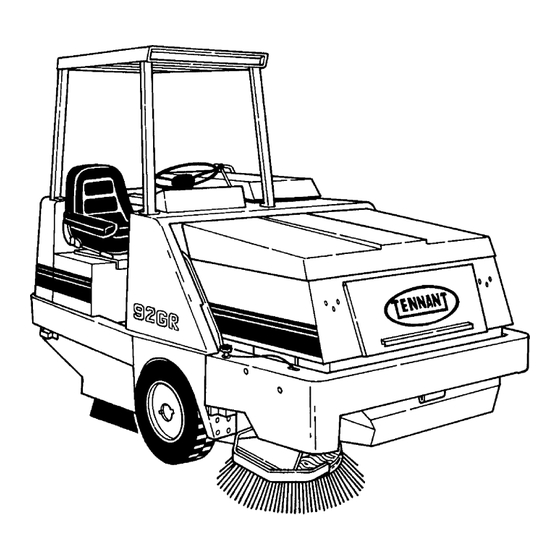
OPERATION OF CONTROLS 04300 MACHINE COMPONENTS A. Operator Seat F. Hopper Inspection Door B. Instrument Panel G. Side Brush C. Overhead Guard H. Side Brush Height Adjustment Knob D. Engine Cover Hopper Support Bar E. Hopper J. Main Brush Access 92GR MM188 (10--- 87) -
Page 18: Controls And Instruments
Y Z AA 04301 CONTROLS AND INSTRUMENTS A. Brake Pedal Q. Dust Filter Shaker Pushbutton Switch B. Directional Pedal R. Dump Door Indicator C. Main Brush Height Adjustment Knob S. Fuel Level Gauge D. Operator Seat T. Engine Coolant Temperature Gauge E. -
Page 19: Brake Pedal
BRAKE PEDAL MAIN BRUSH HEIGHT ADJUSTMENT KNOB The brake pedal operates the mechanical drum The main brush height adjustment knob is located brakes on the two front wheels. behind an access door next to the operator’s left foot. It limits the main brush lift linkage travel. The To stop the machine, return the directional control greater the linkage travel, the greater the amount of pedal to neutral;... -
Page 20: Main Brush Speed Lever
MAIN BRUSH SPEED LEVER The main brush power lift lever raises and lowers the wire brush. It has three positions --- “up”, “”hold”, The main brush speed lever controls the speed of and “down”. the main brush. It has three positions --- “off”, “sweeping”, and “wire brush”. -
Page 21: Throttle Lever
THROTTLE LEVER NOTE: The side brush will not operate unless the main brush is also operating. The throttle lever controls the engine governed speed. HOPPER DOOR LEVER Pushing the lever away from the operator speeds the The hopper door lever controls the hopper door engine to the maximum governed speed. -
Page 22: Main Brush Lift Lever
MAIN BRUSH LIFT LEVER CLOGGED DUST FILTER INDICATOR The main brush lift lever controls the height of the The clogged dust filter indicator lights when the dust main brush. filters become clogged and excessively restrict vacuum air flow. Lower the hopper, shut off the main Pulling the lever back and to the left lowers the main brush and vacuum fan, and push the dust filter brush. -
Page 23: Engine Oil Pressure Gauge
ENGINE OIL PRESSURE GAUGE SIDE BRUSH SWITCH This gauge registers the engine oil pressure. Normal The side brush switch operates an electric actuator engine oil pressure ranges from 7 psi which controls the side brush position. Placing the (50 kPa) at idle, to 35 psi (240 kPa) at full engine switch toggle up in the “up”... -
Page 24: Side Brush Height Adjustment Knob
SIDE BRUSH HEIGHT ADJUSTMENT KNOB The side brush height adjustment knob is located just above the side brush on the front bumper. It controls the height of the side brush. Loosening the knob and sliding it forward lowers the side brush, sliding it backward raises the side brush. Tighten the knob after setting the side brush height. -
Page 25: Hydraulic Pressure Gauge
HYDRAULIC PRESSURE GAUGE FUSES AND CIRCUIT BREAKERS The hydraulic pressure gauge registers the hydraulic Fuses are a one---time circuit protection device pressure in the main brush circuit. Normal down designed to stop the flow of current in the event of a pressure ranges with the brush up and running are circuit overload. -
Page 26: Machine Operation
MACHINE OPERATION NORMAL SWEEPING OPERATION WARNING: Before operating the machine, make sure all safety devices are in place A normal sweeping operation consists of seven and operate properly. Check the foot and parking typical operations: pre---start checklist, starting brakes and the steering control for proper machine, sweeping, dumping hopper, post operation operation. -
Page 27: To Dump Hopper
Pick up oversize debris before sweeping. Flatten or Move the side brush lever into the “off” remove bulky cartons from aisles before sweeping. position. Pick up pieces of wire, twine, string, etc., which Press the filter shaker switch to shake the dust could become entangled in brush or brush plugs. -
Page 28: Post Operation Checklist
Move the main brush power lift lever into the “up” position. Move the main brush speed lever into the “off” position. Move the side brush lever into the “off” position. Turn the operating lamps off if used. Place the throttle lever in the “idle” position. Engage the machine parking brake. -
Page 29: Machine Troubleshooting
MACHINE TROUBLESHOOTING Problem Cause Remedy Excessive dusting Dust skirts and seals worn, Replace or adjust skirts or damaged, not adjusted properly seals Dust filter clogged Shake and/or clean or replace filter Vacuum hose damaged Replace vacuum hose Vacuum fan failure See Hydraulic System Troubleshooting: Poor or no vacuum to brush compartment... -
Page 30: Transporting Machine
TRANSPORTING MACHINE PUSHING OR TOWING MACHINE The front jacking locations are the bottom edge of the machine frame next to the front machine tires. The machine may be pushed from the front or the rear, using the bumpers provided, only after placing the rear wheel on a dolly. -
Page 31: Machine Tie
Lower the machine onto the jack stands. Check to make sure the machine is secure. Service the machine as required. When finished servicing the machine, raise the machine up off the jack stands. 10. Remove the jack stands from under the machine. -
Page 32: Machine Storage
MACHINE STORAGE STORING MACHINE When storing the machine for extended periods of time, the following procedures must be followed to lessen the chance of rust, sludge, and other undesirable deposits from forming. Empty the debris hopper. Change engine oil. Place the main brush height control lever in the “raise”... - Page 33 2-18 92GR MM188 (10--- 87)
-
Page 34: Section 3
SECTION 3 MAINTENANCE CONTENTS Page Page Recommended First 50---Hour Machine Belts and Chains ......3---23 Inspection . - Page 35 Page To Replace Hopper Door Hinge Seal ......3---38 Brakes and Tires ......3---39 Service Brakes .
-
Page 36: Recommended First 50
RECOMMENDED FIRST 50---HOUR MACHINE INSPECTION After the first 50 hours of operation, the following procedures are recommended: Check the brush pattern for correct brush adjustment. Change the hydraulic fluid filter. Check the torque of the engine cylinder head cap screws. Perform all 50---hour interval lubrication and maintenance procedures listed in the Maintenance chart. -
Page 37: Maintenance Chart
MAINTENANCE CHART 04305 MAINTENANCE LOCATIONS 3-65538 92GR MM188 (11--- 87) - Page 38 Flush BF --- Brake fluid EO --- Engine oil HYDO --- Tennant Company or approved hydraulic fluid MPGM --- Multipurpose, water resistant, lithium base, moly---disulphide EP grease WG --- Water and permanent---type ethylene glycol anti---freeze, one---to---one ratio NOTE: More frequent intervals may be required in extremely dusty conditions.
-
Page 39: Lubrication
LUBRICATION ENGINE STEERING GEAR Check the engine oil level daily. Change the engine The steering gear has been lubricated at the factory oil and oil filter after every 50 hours of operation. and should not require any additional lubricant Change the engine oil more frequently if the unless a massive leak occurs. -
Page 40: Side Brush Pivot Pins
SIDE BRUSH PIVOT PINS The five side brush pivot pins should be lubricated with a general purpose, water resistant, lithium base, moly---disulphide EP grease after every 200 hours of operation. 01459 SIDE BRUSH PIVOT PINS A. Pivot Pin B. Side Brush Motor STABILIZER LEG PIVOT PIN The stabilizer leg pivot pin should be lubricated with a general purpose, water resistant, lithium base,... -
Page 41: Hydraulics
TENNANT Hydraulic Fluid, as well as Change the hydraulic fluid after every 400 hours of the other features described. Do not substitute operation. -
Page 42: Hydraulic Fluid Filter
HYDRAULIC FLUID FILTER the parking brake before working on the machine to keep it from rolling. The machine hydraulic system is kept clean to a level of 10 microns by a hydraulic fluid filter. The Jack up the rear of the machine at the hydraulic fluid filter is located on the right side of the designated locations. -
Page 43: Speed Limiter
SPEED LIMITER HYDRAULIC FLUID LEAKS The machine speed limiter limits the maximum Fluid escaping from a very small hole can be almost speed the machine can travel when the hopper is invisible. Use a piece of cardboard or wood, rather raised. -
Page 44: Hydraulic Schematic
04307 HYDRAULIC SCHEMATIC 3-65545 92GR MM188 (11--- 87) -
Page 45: Hydraulic System Troubleshooting
HYDRAULIC SYSTEM TROUBLESHOOTING Problem Cause Remedy Machine travels slowly or Parking brake engaged Release parking brake not at all Control linkage broken or Replace and/or adjust not adjusted properly linkage Relief valve stuck open Clean or replace relief valve --- (leaking) one forward, one reverse Motor failure... - Page 46 Problem Cause Remedy Hopper will not lower Hydraulic control valve See Hydraulic Components failure Troubleshooting Lift cylinder failure See Hydraulic Components Troubleshooting Gear pump failure See Hydraulic Components Troubleshooting Lift arms binding Replace and/or adjust lift arm linkage Hopper door will not roll out Hydraulic control valve See Hydraulic Components failure...
-
Page 47: Hydraulic Components Troubleshooting
HYDRAULIC COMPONENTS TROUBLESHOOTING Problem Cause Remedy Hydraulic cylinder failure Piston seals leaking Install seal kit Barrel worn or rod bent Replace cylinder Hydraulic control valve Valve seals leaking Install seal kit failure Relief valve stuck open Clean or replace relief valve (leaking) Hydraulic motor failure Motor leaking... -
Page 48: Engine
ENGINE ENGINE LUBRICATION dirt, etc., between the fins, if necessary. This should be done only after the radiator has cooled off to Check the engine oil level daily. Change the engine avoid cracking caused by uneven cooling. oil and oil filter after every 50 hours of operation. Change the engine oil more frequently if the Before cleaning, remove the fan shroud from the environment is extremely dusty. -
Page 49: Air Filter Restriction Indicator
components secure and in good condition to prevent Service the air filter element only when the restriction entrance of unfiltered air. indicator indicates excessive restriction in the system. Do not remove air filter element unless it is Overmaintenance can cause more damage than restricting air flow. -
Page 50: Fuel System
Slide a new filter element into the filter housing, drain knob when diesel fuel appears. rounded end first. After every 100 hours of operation, the water trap must be cleaned as described in To Clean Water Trap. TO CLEAN WATER TRAP Stop the engine and engage the machine parking brake. -
Page 51: Fuel Filter
FUEL FILTER FUEL INJECTION PUMP The fuel filter is mounted on the top right side of the The fuel injection pump controls the engine speed. engine. The fuel filter should be replaced after every The maximum speed screw is set and sealed by the 400 hours of operation. -
Page 52: Priming The Fuel System
Tighten injectors evenly to 52 ft lb (70 Nm). flows free of air. Injectors should be taken out only if engine is malfunctioning as outlined below: Misfiring Knocking in one (or more) cylinders C. Engine overheating Loss of power Smoky exhaust (black or white) F.Increased fuel consumption 01475 INJECTION PUMP VENTS... -
Page 53: Diesel Fuel Troubleshooting
DIESEL FUEL TROUBLESHOOTING Problem Cause Remedy Engine will not start Out of fuel Fill fuel tank Filter plugged Clean filter Air in fuel Bleed fuel lines Water in fuel Drain water trap Fuel too thick Change fuel grade Battery discharged Charge or replace battery Clogged fuel nozzle Clean or replace nozzle... -
Page 54: Cylinder Head
CYLINDER HEAD NOTE: Power wrench torque limit must be held at least 10 ft lb (14 Nm) below hand torque specification; then hand torque to the specifications. CYLINDER HEAD The proper sequence and torque values should be used when reassembling the cylinder head. The VALVE TAPPET CLEARANCE ADJUSTMENT cylinder head bolts must be tightened in the proper The valve tappet clearance must be checked after... -
Page 55: Electrical System
ELECTRICAL SYSTEM BATTERY If when checking battery specific gravity, one or more battery cells tests lower than the other battery The battery is rated at 12 V, 625 ccA. It is located cells, (0.050 or more) the cell is damaged, shorted, next to the engine and hydraulic pump. -
Page 56: Electrical Schematic
04309 ELECTRICAL SCHEMATIC 3-65557 92GR MM188 (11--- 87) -
Page 57: Electrical Schematic, Accessories
01502 ELECTRICAL SCHEMATIC, ACCESSORIES 3-65558 92GR MM188 (11--- 87) -
Page 58: Belts And Chains
BELTS AND CHAINS ENGINE FAN BELT STATIC DRAG CHAIN To tighten the fan belt, loosen the alternator A static drag chain is provided to prevent the buildup adjusting bolts and pull out on the alternator by hand of static electricity in the machine. The chain is until the belt is just snug. -
Page 59: Debris Hopper
DEBRIS HOPPER HOPPER DUST FILTERS Disconnect the shaker motor wire connectors. There are two dust filter cartridges located inside of Remove the two dust filter spring mounting the hopper. The dust filters filter the air which is bolts from each spring set with a 0.25 in allen drawn up from the main brush compartment through wrench. -
Page 60: To Install Hopper Dust Filters
Lift the dust filter shaker assembly off each of Place the four shaker shims in position. the dust filter elements. Slide the dust filter shaking assemblies in position over the dust filters. Thread the two allen head socket bolts through the mounting springs and into the dust filter frames of each filter. -
Page 61: Debris Hopper
Slide a new fusible link over the link mounting WARNING: Always stop the machine on a pins. level surface, stop the engine, and engage the parking brake before working on the machine to keep it from rolling. Slide a 1.5 in (40 mm) thick block under each side of the rear of the hopper. -
Page 62: To Adjust Stabilizer Leg
TO ADJUST STABILIZER LEG Place the hopper in the “operating” position. Make sure the front bumper is not resting on the stabilizer leg assembly. If it is, loosen the leg assembly mounting bolts, slide the assembly down, and retighten the bolts. Loosen the activating arm pinch bolt. -
Page 63: Brushes
BRUSHES MAIN BRUSH/WIRE BRUSH The main brush/wire brush should be inspected daily for wear or damage. Remove any string or wire found tangled on the brush, brush drive hub, or brush idler hub. Rotate the brush end---for---end after every 50 hours of operation for maximum brush life. -
Page 64: Brush
01486 MAIN BRUSH IDLER ARM A. Brush Idler Arm B. Plastic Screw C. Arm Retaining Bolt Pull the brush idler arm off the arm hub. NOTE: If the brush idler arm does not come off easily, remove the plastic screw located next to the hole where the brush idler arm retaining bolt was mounted. -
Page 65: To Check And Adjust Main Brush Pattern
13. Align the main brush idler plug slots with the main brush keys. 14. Slide the main brush idler plug into the main brush tube. 15. Slide the brush idler arm onto the arm hub. 00582 16. Thread the brush idler arm retaining bolt NORMAL MAIN BRUSH PATTERN through the idler arm and into the arm hub. -
Page 66: To Check And Adjust Wire Brush Pattern
Tighten the locking wing nut and recheck the main The side brush should be replaced when the brush pattern. Repeat the procedure until the main remaining brush bristle measures 2.5 in (65 mm) in brush pattern is within the specified range. length. -
Page 67: To Adjust Side Brush Maximum Height
Loosen the side brush stop bolts. Position the side brush stop down so the bottom of the side brush is 1 in (25 mm) from the floor when it is in the “raised” position. Tighten the stop bolts. 01460 SIDE BRUSH A. -
Page 68: To Adjust Side Brush Bumper Clearance
Loosen the two side brush angle adjustment Stop the engine. bolts. WARNING: Always engage the hopper support bar before working under a raised hopper. Do not rely on the machine hydraulic system to keep the hopper in the “raised” position. The hydraulic system may leak internally, allowing the hopper to lower, crushing anything under it. -
Page 69: Skirts And Seals
SKIRTS AND SEALS HOPPER LIP SKIRTS The hopper lip skirts are located on the bottom rear of the hopper. Their purpose is to float over debris and help deflect that debris into the hopper. The hopper lip skirts are made up of five bottom lip segments. -
Page 70: Brush Door Skirts
Raise the hopper, engage the hopper support BRUSH DOOR SKIRTS bar, and lower the hopper onto the hopper The brush door skirts are located on the bottom of support bar. each of the two brush compartment doors. These skirts seal the brush compartment. The seals should WARNING: Always engage the hopper be inspected for wear or damage daily. -
Page 71: Rear Skirts
Slide the brush door skirt up or down so that Remove the main brush as described in Main the skirt clears the floor up to a maximum Brush Replacement. clearance of 0.12 in (3 mm). Remove the front skirt mounting bracket Tighten the skirt retaining bolts. -
Page 72: Door Seal
Raise the hopper, engage the hopper support Remove the seal from the seal backing plate. support bar, and lower the hopper onto the Install a new seal on the backing plate. support bar. Bolt the seal and backing plate to the cross WARNING: Always engage the hopper shaft. -
Page 73: Hinged Top Hopper Seal
Have an assistant watch the dust dump door WARNING: Always engage the hopper cam follower as the hopper lowers. The cam support bar before working under a raised should contact the upper corner and ride on hopper. Do not rely on the machine hydraulic top of the main frame and close the dust dump system to keep the hopper in the “raised”... -
Page 74: Hopper Door Hinge Seal
10. Open the right brush door. Remove the two seal retainers and the old hinge seal. 11. Remove the main brush. 12. Looking through the right brush door opening, check to make sure approximately three---fourths of the top seal is making contact with the machine frame. -
Page 75: Brakes And Tires
BRAKES AND TIRES SERVICE BRAKES Make sure that the brake fluid reservoir is full and that the vent in the cap is open. The service brakes are hydraulically activated by a master brake cylinder. Check the master brake Connect a plastic or rubber tube to the bleeder cylinder fluid level after every 400 hours of operation valve on the left front wheel. -
Page 76: Parking Brakes
PARKING BRAKES The parking brakes are mechanically activated by the parking brake lever and two cables. The parking brakes should be adjusted whenever the machine rolls after engaging the parking brake, or when it becomes very easy to engage the parking brake, and after every 50 hours of operation. -
Page 77: Section 4
SECTION 4 APPENDIX CONTENTS Page Hardware Information ..... . Standard Bolt Torque Chart ....Metric Bolt Torque Chart . -
Page 78: Hardware Information
HARDWARE INFORMATION The following charts state standard plated hardware BOLT IDENTIFICATION tightening ranges for normal assembly applications. Identification Specification Decrease the specified torque by 20% when using a Grade Marking and Grade thread lubricant. Do not substitute lower grade ____________________________________________________ hardware for higher grade hardware. -
Page 79: Hydraulic Fitting Information
HYDRAULIC FITTING INFORMATION HYDRAULIC TAPERED PIPE FITTING (NPT) HYDRAULIC O-- RING FITTING TORQUE CHART TORQUE CHART Tube Thread Minimum Maximum O.D.(in) Size Torque Torque ______________________________________________________________ NOTE: Ratings listed are when using teflon thread 0.25 0.44--- 20 6 ft lb (8 Nm) 9 ft lb (12 Nm) seal.
Need help?
Do you have a question about the 92 GR and is the answer not in the manual?
Questions and answers