Tennant T7 Operator's Manual
Hide thumbs
Also See for T7:
- Service information manual (88 pages) ,
- Operator's manual (54 pages) ,
- Instruction bulletin (11 pages)
Table of Contents
Advertisement
Quick Links
Advertisement
Table of Contents
Troubleshooting

Subscribe to Our Youtube Channel
Related Manuals for Tennant T7


Summary of Contents for Tennant T7
- Page 1 (Battery) Rider- Scrubber Operator Manual The Safe Scrubbing Alternative Hygenic Fully Cleanable Tanks North America / International 331040 Rev. 06 (12-2014) To view, print or download the latest manual, visit: *331040* www.tennantco.com/manuals...
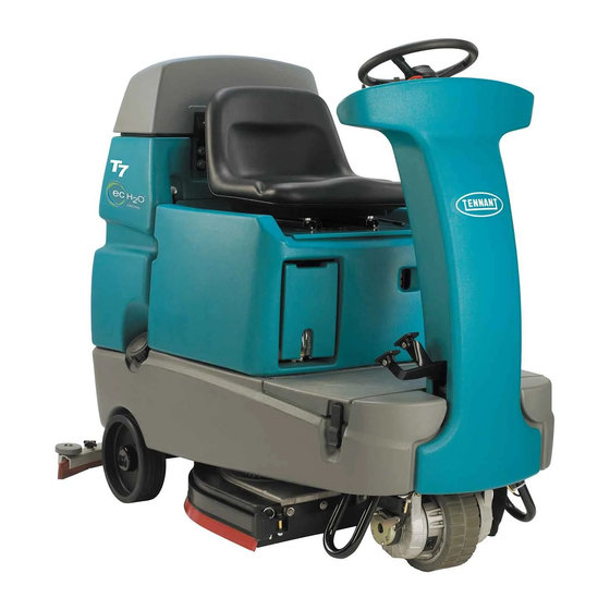
- Page 2 Installation Date - INTENDED USE The T7 is an industrial/commercial rider machine designed to wet scrub both rough and smooth hard surfaces (concrete, tile, stone, synthetic, etc). Typical applications include schools, hospitals / health care facilities, office buildings, and retail centers. Do not use this machine on soil, grass, artificial turf, or carpeted surfaces. This machine is intended for indoor use only.
-
Page 3: Table Of Contents
....Charging The Batteries With The On- Board Charger ....On- Board Battery Charger Error Codes T7 331040 (9- 2013) -
Page 4: Safety Precautions
- Do not carry passengers on machine. - Always follow safety and traffic rules. - Report machine damage or faulty operation immediately. - Follow mixing, handling and disposal instructions on chemical containers. - Follow site safety guidelines concerning wet floors. T7 331040 (9- 2013) - Page 5 - All repairs must be performed by a trained service mechanic. - Do not modify the machine from its original design. - Use Tennant supplied or approved replacement parts. - Wear personal protective equipment as needed and where recommended in this manual.
- Page 6 Electrical components, use cause explosion or fire. Do not grounding strap before pick up. opening panel. Located on electrical panel under the seat Located under the solution fill port and next to foot pedals T7 331040 (9- 2013)
-
Page 7: Operation
S. Battery charging connector H. Scrub head T. Propel pedal I. Steering wheel U. Brake pedal J. Solution tank K. Tool Box or optional FaST- PAK compartment ec- H2O System Module (option) L. Solution tank fill cap T7 331040 (02- 09) -
Page 8: Controls And Instruments
K. ec- H2O system indicator light (option) L. Vacuum fan / squeegee button M. Brush Pressure increase button (+) N. Brush Pressure decrease button (- ) O. Solution increase button (+) P. Solution decrease button (- ) Q. Control panel cover T7 331040 (02- 09) -
Page 9: How The Machine Works
BRUSH INFORMATION section of this tank. Drain, rinse and refill the solution tank with manual or contact a Tennant representative. clear cool water before operating the FaST system. Conventional cleaning detergents may cause failure to the FaST system. -
Page 10: Ec- H2O Scrubbing (Ec- H2O Model)
Polishing pad - This white pad is for polishing floors. Maintains a high gloss. Use for buffing very soft finishes and lower traffic areas, and polishing soft waxes on wood floors. T7 331040 (9- 2013) -
Page 11: Machine Setup
8. When replacing an empty FaST- PAK carton, slide the empty FaST- PAK approximately half you must scrub with the FaST system for a way out from the FaST- PAK compartment few minutes before the detergent will reach its door. maximum foaming. T7 331040 (9- 2013) -
Page 12: Filling The Solution Tank
Plan the scrubbing in advance. Try to arrange long runs with minimum stopping and starting. Do an entire floor or section at one time. Pre- sweep the area to prevent streaking. T7 331040 (9- 2013) -
Page 13: Setting Scrub Modes
(See settings (middle or top lights). Travel speed and page 15). floor conditions will affect scrubbing performance. ec- H2O System Indicator Light T7 331040 (02- 09) -
Page 14: Economy Setting
NOTE: DO NOT turn the ec- H2O/FaST system on during conventional scrubbing. Conventional cleaning detergents/restorers may cause failure to the FaST/ec- H2O solution system. Drain, rinse and refill solution tank with cool clean water before operating the FaST/ec- H2O system. T7 331040 (9- 2013) - Page 15 The light next to the One Step or fire. Do not pick up. Scrub button will turn off and the scrubbing functions will turn off after a short delay. T7 331040 (9- 2013)
-
Page 16: Double Scrubbing
The light above the vacuum fan button will turn off, the squeegee will raise and the vacuum fan will stop operating. Then scrub the area. Let the cleaning solution set on the floor for 3- 5 minutes. T7 331040 (9- 2013) -
Page 17: Water Pickup Mode (No Scrubbing)
Avoid turning the steering wheel too sharply when the machine is in motion. The machine is very responsive to the movement of the steering wheel. Avoid sudden turns, except in emergencies. T7 331040 (9- 2013) -
Page 18: Emergency Stop Button
HOUR METER scrubbing. The hour meter records the number of hours the machine has been powered on. This information is useful for servicing the machine. It is located under the seat. T7 331040 (9- 2013) -
Page 19: Solution Tank Empty Indicator
See BATTERIES in the MAINTENANCE section. NOTE: The blinking left battery discharge light will not reset from blinking until the batteries are fully charged. T7 331040 (9- 2013) -
Page 20: Fault Indicator
Brush Pressure Light overloaded (possibly from string or or Contact Tennant service both blink banding wrapped around motor) representative Fault Light and Vacuum Fan Motor is overloaded Contact Tennant service Vacuum Fan Light representative both blink T7 331040 (02- 09) -
Page 21: Circuit Breakers
The circuit breakers are located inside the battery hazard light. compartment next to the hour meter. The chart shows the circuit breakers and the electrical components they protect. Circuit Breaker Rating Circuit Protected Instrument Panel - power 15 A Accessories T7 331040 (9- 06) -
Page 22: Draining And Cleaning The Tanks
7. Replace the recovery tank drain hose cap and mount the drain hose back onto the mounting clip after the tank is drained. T7 331040 (9- 2013) - Page 23 11. Tilt the recovery tank back to access the solution tank cover. Wipe the bottom of the solution tank. Make sure the recovery tank is cover and the tank seal before replacing the empty before tilting. cover. T7 331040 (9- 2013)
-
Page 24: Propel System Troubleshooting
8 times Horn repeatedly ON/OFF key switch is turned on while Unplug battery charger before starting beeps 9 times battery charger is plugged into machine machine Fault Light blinks Propel motor is overloaded Contact Tennant service representative T7 331040 (9- 2013) -
Page 25: Machine Troubleshooting
Worn scrub brush Replace scrub brush Broken or loose brush drive belt Replace or tighten belt (Cylindrical models) Brush pressure set too light Increase brush pressure Low battery charge Charge batteries until the charger automatically turns off T7 331040 (02- 09) - Page 26 H2O Model: Defective light or module Contact Service Center ec- H2O system indicator light does not turn on ec- H2O Model: Clogged module Contact Service Center No water flow Defective solution pump Replace solution pump T7 331040 (02- 09)
-
Page 27: Maintenance
MAINTENANCE MAINTENANCE 355033 T7 331040 (02- 09) -
Page 28: Maintenance Chart
500 hour check) Tires Check for damage and wear 1000 FaST water and air Replace Hours filters (option) LUBRICANT/FLUID ..Distilled water NOTE: More frequent maintenance intervals may be required in extremely dusty conditions. T7 331040 (9- 2013) -
Page 29: Batteries
Add distilled water if low. DO NOT OVERFILL. The electrolyte will expand and may overflow when charging. Before Charging After Charging NOTE: Make sure the battery caps are in place while charging. T7 331040 (9- 2013) -
Page 30: Charging The Batteries With Off- Board Charger
OFF- BOARD CHARGER NOTE: If the red “ABNORMAL CYCLE” lamp IMPORTANT: Before charging, make sure that lights when the TENNANT charger is plugged into the charger setting is properly set for the a wall outlet, the charger cannot charge the battery type. -
Page 31: Checking On- Board Battery Charger Settings
Keep covers open when charging. 4. Connect the charger’s AC power supply cord into a properly grounded wall outlet. To change the settings to use a different type of battery, contact your Tennant Service representative. T7 331040 (9- 06) -
Page 32: On- Board Battery Charger Error Codes
E03 reappears check battery or ies undercharged due to a sulfated replace it. or faulty battery. Safety timer exceeded maximum Replace battery. charging time. Interrupts charging cycle. Possible internal short circuit. Contact Service Center. T7 331040 (06- 06) -
Page 33: Electric Motors
Proper belt tension is a 6 mm (0.25 in) deflection from a force of 2.3 to 2.5 kg (5.0 to 5.4 lb) at the belt midpoint. Check and adjust the belt tension every 100 hours of operation. T7 331040 (9- 2013) -
Page 34: Scrub Brushes And Pads
Otherwise one brush or pad will be more aggressive than the other. 4. Open the side squeegee retainer pivot toward the front of the machine, then pull the side squeegee toward the rear of the machine to access the scrub brushes or pads. T7 331040 (9- 2013) -
Page 35: Replacing Disk Pads
7. Close the side squeegee and the retainer pivot, then insert the pin. 4. Reinsert the pad driver into the machine. NOTE: Be sure the pin is inserted completely through the bottom. T7 331040 (9- 2013) -
Page 36: Cylindrical Brushes
The idler door of that side of the scrub head is stamped with the same letter. Make sure the letter on the door matches the letter on the scrub head when replacing the doors. T7 331040 (9- 2013) -
Page 37: Checking Cylindrical Brush Pattern
6. Observe the brush patterns. If the brush pattern is the same width across the entire length of each brush and both brushes are the same width, no adjustment is necessary. 10653 10355 T7 331040 (9- 2013) -
Page 38: Adjusting Cylindrical Brush Taper
Tighten the mounting screw. 4. Remove idler plate from the scrub head by pressing the spring tab downward. 7. Check the brush patterns again and readjust as necessary until both patterns are the same. T7 331040 (9- 2013) -
Page 39: Adjusting Cylindrical Brush Width
4. Loosen the jam nut, then adjust the brush width adjustment screw. Tighten the jam nut and the two scrub head mounting screws when finished. 5. Check the brush patterns again and readjust as necessary until both brush patterns are the same. T7 331040 (9- 2013) -
Page 40: Fast System Maintenance (Fast Model)
2. Remove the injector assembly from the pinch clamps. 3. Replace the water and air filter. An 8mm hex wrench is required to install the new water filter. Air Filter (50 Mesh/Brown) Water Filter (50 Mesh/Brown) T7 331040 (9- 2013) -
Page 41: Ec- H2O System (Ec- H2O Model)
4. Turn the key to the on position. The rear squeegee assembly can be removed from the squeegee pivot to prevent damage during transport of the machine. T7 331040 (9- 2013) -
Page 42: Replacing (Or Rotating) The Rear Squeegee Blades
8. Install the new front squeegee blade or rotate the existing blade to the new edge. Be sure the holes in the front squeegee blade are hooked onto the tabs on the front blade clamp. 9. Lightly tighten the two outer knobs. T7 331040 (9- 2013) -
Page 43: Replacing Side Squeegee Blades
1. Open the side squeegee. 12. Tighten the rear squeegee retaining band tension latch. 2. Pull the old side squeegee blade from the side squeegee retainer. Slide the new blade onto the retainer. 3. Close the side squeegee. T7 331040 (9- 2013) -
Page 44: Adjusting The Squeegee Guide Roller
2. Turn off the machine ON/OFF key switch. FOR SAFETY: Before leaving or servicing machine, stop on level surface, turn off machine, and remove key. 3. Look at the deflection of the squeegee over the full length of the squeegee blade. T7 331040 (9- 2013) -
Page 45: Adjusting Rear Squeegee Blade Deflection
12 mm (0.50 in) for scrubbing the squeegee blade deflection after smooth floors and 15 mm (0.62 in) for rough adjustments are made. floors. 6. Readjust the squeegee blade deflection if necessary. 12 mm (0.50 in) 03719 T7 331040 (9- 2013) -
Page 46: Skirts And Seals
The recovery tank seal is located on the bottom of damage and wear after every 500 hours of the recovery tank cover. Check the seal for operation. damage and wear after every 100 hours of operation. T7 331040 (9- 2013) -
Page 47: Pushing, Towing, And Transporting The Machine
7. Route the rear tie- down straps through the remove the screw driver to enable the parking opening at the center part of the rear axle. brake. FOR SAFETY: Do not operate machine with the brake disabled. T7 331040 (9- 2013) -
Page 48: Machine Jacking
(ec- H2O switch indicator light will turn red). If this occurs, reset 3. Remove the batteries, or charge them every key and repeat the flush procedure as described three months. below. T7 331040 (9- 2013) -
Page 49: Flushing Antifreeze From Ec- H2O Module
When the water turns clear, press the module switch again to stop the flush cycle. Dispose the antifreeze in an environmentally safe way according to local waste disposal regulations. 5. The machine is now ready for scrubbing. T7 331040 (9- 2013) -
Page 50: Specifications
1840 mm (72.5 in) Travel Speed (maximum) 6.4 Km/h (4 mph) Maximum rated climb and descent angle with full tanks 10.5% Maximum rated climb and descent angle with empty tanks 19.25% Maximum rated climb and descent angle when scrubbing T7 331040 (9- 2013) -
Page 51: Power Type
70 psi bypass setting Solution flow rate* 1.1 L/min (0.30 gpm) Disk model 1.5 L/min (0.40 gpm) Cylindrical brush model 1.9 L/min (0.50 gpm) Optional * If the optional solution flow rates are required, contact an Authorized Service Center. T7 331040 (02- 09) -
Page 52: Machine Dimensions
800 mm (33.25 in) For 800 mm (32 in) squeegee 1000 mm (39.25 in) 1270 mm (50 in) Frame (Disk) 740 mm (29 in) Frame (Cyl) 1520 mm 810 mm (31.7 in) (60 in) 1014751 MACHINE DIMENSIONS T7 331040 (9- 06) -
Page 53: Index
Flushing ec- H2O System Module, ec- H2O Contents, 1 Module, 39 Controls and Instruments, 6 Foam Scrubbing System (Fast Mode), 7 Conventional Scrubbing, 7 Freeze protection, 46 Cylindrical brushes, 34 ec- H2O System, 46 Fuses, 19 T7 331040 (9- 2013) - Page 54 Setting FaST Button, 11 Pushing or Towing the Machine, 45 Setting Solution Flow (Conventional Transporting the Machine, 45 Scrubbing Only), 11 Solution Tank Empty Indicator, 17 Water Pickup Mode (No Scrubbing), 15 While Operating the Machine, 15 T7 331040 (9- 2013)
- Page 55 Setting Brush Pressure, 11 Water Pickup Mode (No Scrubbing), 15 Setting FaST Button, 11 While Operating the Machine, 15 Setting Scrub Modes, 11 Setting Solution Flow (Conventional Scrubbing Only), 11 Side Squeegee Blades, 41 Replacing Side Squeegee Blades, 41 T7 331040 (9- 2013)
Need help?
Do you have a question about the T7 and is the answer not in the manual?
Questions and answers