Table of Contents
Advertisement
Quick Links
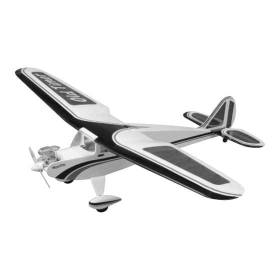
Wingspan: 73 in [1854mm]
Wing Area: 735 sq in [47 dm
Weight: 5-1/4 lb [2434 g]
Wing Loading: 17 oz/sq ft [52 g/dm
Fuselage Length: 55 in [1397mm]
Radio: 3-Channel
Engine: .30 – .40 cu in two-stroke,
.40 – .52 cu in four-stroke
Model Manufacturing Co. guarantees this kit to be free from defects in both material and workmanship at the date of purchase.
Great Planes
®
This warranty does not cover any component parts damaged by use or modification. In no case shall Great Planes' liability exceed the
original cost of the purchased kit. Further, Great Planes reserves the right to change or modify this warranty without notice.
In that Great Planes has no control over the final assembly or material used for final assembly, no liability shall be assumed nor accepted for
any damage resulting from the use by the user of the final user-assembled product. By the act of using the user-assembled product, the user
accepts all resulting liability.
If the buyer is not prepared to accept the liability associated with the use of this product, the buyer is advised to return this kit
immediately in new and unused condition to the place of purchase.
READ THROUGH THIS MANUAL BEFORE STARTING
CONSTRUCTION.
INSTRUCTIONS AND WARNINGS CONCERNING
THE ASSEMBLY AND USE OF THIS MODEL.
OLD4P03 for GPMA0495 V1.0
INSTRUCTION MANUAL
2
]
2
]
IT
CONTAINS
WARRANTY
IMPORTANT
™
1610 Interstate Drive Champaign, IL 61822
(217) 398-8970, Ext. 2
airsupport@greatplanes.com
Entire Contents © Copyright 2002
Advertisement
Table of Contents

Related Manuals for GREAT PLANES Old Timer


Summary of Contents for GREAT PLANES Old Timer
-
Page 1: Instruction Manual
Further, Great Planes reserves the right to change or modify this warranty without notice. In that Great Planes has no control over the final assembly or material used for final assembly, no liability shall be assumed nor accepted for any damage resulting from the use by the user of the final user-assembled product. -
Page 2: Table Of Contents
40 is a very gentle, easy to fly Die Patterns ..............6 & 7 plane. The classic lines of the Old Timer 40 will bring back BUILDING THE TAIL SURFACES..........8 memories of when R/C was in its infancy. The Old Timer 40 Build the Stabilizer and Elevator ..........8... -
Page 3: Decisions You Must Make
.40 - .52 cu. in. 4-stroke and true. The Old Timer 40 is a large airplane, but is built very light. When it was test flown, the O.S. ® .40LA engine provided Before starting to build, compare the parts in this kit plenty of power. -
Page 4: Adhesives & Building Supplies
Bar Sanders and ™ replaceable Easy-Touch Adhesive-backed Sandpaper. Great Planes CG Machine ™ (GPMR2400) While building the Old Timer 40, we used three 11" Bar Top Flite Precision Magnetic Prop Balancer ™ Sanders equipped with 80-grit, 150-grit and 220-grit (TOPQ5700) Adhesive-backed Sandpaper. -
Page 5: Important Building Notes
• Photos and sketches are placed before the step they IMPORTANT BUILDING NOTES refer to. Frequently you can study photos in following steps to get another view of the same parts. • There are two types of screws used in this kit: •... -
Page 6: Die Patterns
DIE PATTERNS... -
Page 7: Die Patterns
DIE PATTERNS... -
Page 8: Building The Tail Surfaces
Cover the stabilizer/elevator plan with wax paper or Great Planes Plan Protector so glue will not adhere. 8. From the remaining 1/4" x 1/2" [6.4mm x 12.7mm] balsa stick, cut and glue the stabilizer TE doubler to the TE and the aft stabilizer center to the TE doubler. -
Page 9: Ca Lamination Method
Note: If you work quickly, the previous strip will still be wet CA Lamination Method on the outside. This will accelerate the CA, securing the strips to one another immediately. If you crack the strip, don’t worry. Just hold it in place until the CA cures and then, seal it with thin CA if necessary. -
Page 10: Finish The Stab & Elevator
6. After the wood strips have dried, remove the pins 4. Cut the stab outer frame between the elevator LE and holding the strips in position. The strips should closely hold the stab TE. Separate the stab from the elevator. Sand the the shape of the stabilizer. -
Page 11: Install The Hinges
CA hinges. 3. To cut the hinge slot, first locate the centerline of the LE and TE edges using the Great Planes Precision Hinge 6. From the 1/8" x 1/4" x 30" [3.2mm x 6.4mm x 762mm] Marking Tool (GPMR4005). - Page 12 the location, press the button on the handle and the blades will cut easily into the balsa wood. IF YOU DO NOT HAVE A SLOT MACHINE 6. Lay the rudder over the fuse plan and mark the location for the tailgear wire. Cut the hinge slot in the rudder, fin, stab and elevator using a Hobby Knife with a #11 blade.
-
Page 13: Finish The Tail Surfaces
3/32" [2.4mm] high. 1. Cover the center wing panel plan from W-4 to W-4 with waxed paper or Great Planes Plan Protector. Note: You may need to adjust the height of the rudder with card stock so your “bevel to” line is not too high. - Page 14 3. Position one of the main spars over the plan and pin it to the building board. Because the wing uses a center shear 7. Insert the die-cut 3-ply wing dowel support at the web, the main spar can only be pinned outboard of the front of ribs W2.
-
Page 15: Sheet The Bottom Of The Wing Center-Section
12. Use a sanding bar with 150-grit sandpaper to sand the top of the sub LE and wing dowel support flush with the top of the ribs. 16. From the remaining 1/16" [1.6mm] balsa sheets cut in step 13, sheet the center-section of the wing. 13. - Page 16 5. Glue the 1/16" x 1-1/2" x 16-1/2" [1.6mm x 38mm x 419mm] balsa strip to the aft edge of the ribs, flush with the aft edge of the TE. 2. Pin the top wing spar flat against your building board. Position the 1/4"...
-
Page 17: Build The Outer Wing Panels
1. Cover the left wing panel plan from W-4 to the wing to shape the LE to the shape shown on the wing plan. tip with waxed paper or Great Planes Plan Protector. Note: The outer wing panel will first be assembled without glue. - Page 18 7. Carefully trim or sand the TE of the ribs to match the angle of the 1/4" [6.4mm] TE stick. 13. To glue the forward wing sheet to the top of the wing, apply a bead of medium CA to the forward half of the top main spar.
-
Page 19: Sheet The Bottom Of The Outer Wing Panel
CA to the forward half of the bottom main spar. Position the wing sheet so that the 11. Use a Great Planes Power Plane and sanding bar aft edge of the sheet is centered on the bottom main spar. -
Page 20: Join The Wing Panels
16. From the 1/8" x 5/8" x 30" [3.2mm x 15.9mm x 762mm] balsa stick, cut and glue wing tip braces to the top of the wing tip as shown on the plan. 13. Using a hobby knife, carefully cut a slot in the root rib W4 and rib W5 to allow the die-cut 1/8"... -
Page 21: Build The Fuselage
Build the Fuselage Sides 1. Cover the fuselage plan side view with waxed paper or Great Planes Plan Protector. When installing the formers, make sure the embossed lettering is always facing forward. 4. Make a mark at the center of the TE of the center wing panel. - Page 22 9. Place the two fuse sides together and check that they match up all the way around. If they are not identical, pin them together and use a sanding bar to make them match. 10. Lightly sand both sides of each fuselage side to remove any excess glue.
-
Page 23: Assemble The Aft Fuse Top
Assemble the Aft Fuse Top 1. Cover the Aft Fuse Deck plan, at the bottom of the fuse plan, with waxed paper or Great Planes Plan Protector. 15. Glue the 1/8" x 3/16" x 24" [3.2mm x 4.8mm x 609.6mm] balsa fuse side doublers to the top and bottom of the fuse. -
Page 24: Assemble The Fuselage
1. Cover the Fuselage Top View plan with waxed paper the centerline. Do not put the tape over the top of the fuse. or Great Planes Plan Protector. You will need to check fit the aft fuse deck . 2. Lay the right fuse side on your building board. Align the front of the fuse with the front of the fuse plan. - Page 25 10. Fit the die-cut 3-ply servo tray in the fuselage. To install 13. Glue the die-cut 3-ply instrument panel (IP) the tray in former F2 you will need to insert one side of the perpendicular to the forward top tray. servo tray over F2 and slide it down as far as possible.
-
Page 26: Finish The Bottom Of The Fuselage
top of the sheet. If it is not, trim the notch slightly until the rail fits properly. Use 6-minute epoxy to glue the landing gear rail to the fuse side and the front of former F2. Wipe off any excess epoxy. Pay special attention to the underside of the rail where the 1"... - Page 27 fuselage. Save the remaining outer pushrod tube for the throttle outer pushrod tube. 6. Glue a die-cut 3-ply servo mount backup to the bottom of the servo tray at both ends of the opening for the rudder and elevator servo. Determine which side your throttle servo will need to be mounted on.
-
Page 28: Mount The Wing On The Fuselage
Mount the Wing on the Fuselage 1. Position the wing in the wing saddle and visually align it with the fuselage. 5. Use a 1/4"-20 tap to cut threads into the wing hold down blocks. After cutting the threads, put a couple of drops of thin CA on the threads in the wing hold down blocks. - Page 29 5. Sight down the fin, checking that it is in line with the centerline of the fuselage. It is very important that the fin be aligned with the centerline of the fuse and perpendicular to the stab. If it is not, the plane will be difficult to trim for straight flight.
-
Page 30: Mount The Landing Gear
Mount the Landing Gear 6. Temporarily secure the main landing gear to the landing gear rail with the landing gear straps and four #2 x 3/8" screws. Assemble the Wheel Pants 1. Turn the fuse upside-down. On one end of the landing gear rail make, in the groove, a mark 3/4"... - Page 31 5. Use masking tape to join the two wheel pant halves. 10. Slide the wheel pant over the landing gear wire so Carefully spot glue them together in just a few places with that the wire is recessed into the slot in the wheel pant. thin CA.
-
Page 32: Install The Landing Gear Fairing
2. Use a sanding bar to round the leading and trailing edge of the fairing. 16. Before painting the wheel pant, fill the seams with filler such as Bondo ® Auto Body Filler or an automotive scratch and dent glazing compound. We use Bondo most of the time as it cures quickly and sands easily, but it is normally sold in large quantities. -
Page 33: Install The Engine
You may also need to trim the fuse side to clear the muffler. RADIO INSTALLATION 2.Use a Great Planes Dead Center Hole Locator (GPMR8130) ™ or something similar to mark the location of the mounting holes onto the engine tray. - Page 34 6. Mount the receiver switch on the side of the fuse, elevator and rudder pushrods cross the mounting holes in opposite the engine exhaust. We use a Great Planes Switch the servo arms. Note: The servo arms have been painted &...
-
Page 35: Install The Throttle Pushrod
nylon FasLink ™ on each pushrod and cut the wire so it slightly protrudes out of the FasLink. Note: If necessary, enlarge the holes in the servo arms with a 5/64" [1.9mm] drill bit (or a #48 drill for precision). 6. -
Page 36: Finishing
The procedure that was used to cover the Old Timer 40 uses a template made from paper for the white and transparent blue covering. -
Page 37: Suggested Covering Sequence
We used Top Flite MonoKote White (TOPQ0204), FINAL HOOKUPS & CHECKS Transparent Blue (TOPQ0304), Light Purple (TOPQ0224) and Black (TOPQ0208) to cover our Old Timer 40. Suggested Covering Sequence Install the Hinges Fuselage and Tail: 1. Cut the covering from the hinge slots in the elevator 1. -
Page 38: Install The Wheels
Finish the Model 3. Apply 6 drops of thin CA adhesive to both sides of each hinge. Allow a few seconds between drops for the CA to wick into the slot. Use a paper towel to wipe off any 1. Reinstall the elevator and rudder control horns. Insert excess CA that may have gotten onto the covering. -
Page 39: Get The Model Ready To Fly
Flying your model at these throws will provide you with the greatest chance for successful first flights. If, after you have become accustomed to the way the Old Timer 40 flies, you would like to change the throws to suit your taste, that is fine. -
Page 40: Preflight
(ready to fly) and an empty fuel tank, place battery pack you just purchased, should be cycled, noting the model right side-up on a Great Planes CG Machine, or the discharge capacity. Oftentimes, a weak battery pack can lift it right side-up at the balance point you marked. -
Page 41: Ground Check
We use a Top Flite Precision Magnetic Prop Balancer ™ (TOPQ5700) in the workshop and keep a Great Planes Keep these items away from the prop: loose clothing, shirt Fingertip Prop Balancer (GPMQ5000) in our flight box. sleeves, ties, scarfs, long hair or loose objects such as pencils or screwdrivers that may fall out of shirt or jacket pockets into the prop. -
Page 42: Radio Control
Be sure to check the items off as they are completed (that’s why it’s called a check list! ). The Old Timer 40 is a great-flying model that flies smoothly and predictably. The Old Timer 40 does not, however, 1. -
Page 43: Takeoff
While full throttle is usually desirable GOOD LUCK AND GREAT FLYING! for takeoff, the Old Timer 40 flies great at half throttle on a .40 size engine. Take it easy with the Old Timer 40 for the first few flights, gradually getting acquainted with it as you gain confidence. -
Page 44: Two View
TWO VIEW DRAWING Use copies of this page to plan your trim scheme...
Need help?
Do you have a question about the Old Timer and is the answer not in the manual?
Questions and answers