Table of Contents
Advertisement
Quick Links
Advertisement
Table of Contents

Subscribe to Our Youtube Channel
Related Manuals for kincrome K15310


Summary of Contents for kincrome K15310
- Page 1 BENCH DRILL PRESS Operation and Safety Instructions PART No. K15310...
-
Page 2: Table Of Contents
Table of contents SECTION PAGE Technical data ............2 General safety rules . -
Page 3: General Safety Rules
II. General safety rules Safety is a combination of common sense, staying alert, and knowing how your bench drill press works. WARNING: TO AVOID MISTAKES THAT COULD CAUSE SERIOUS INJURY, DO NOT PLUG IN THE BENCH DRILL PRESS UNTIL THE FOLLOWING STEPS HAVE BEEN READ AND UNDERSTOOD. - Page 4 II. General safety rules ... continued 16. DO NOT operate the tool if you are under the influence of drugs, alcohol or medication that could affect your ability to use the tool properly. 17. CHECK FOR DAMAGED PARTS. Check for alignment of moving parts, jamming, breakage, improper mounting, or any other conditions that may affect the tool’s operation.
-
Page 5: Specific Safety Rules For Bench Drill Presses
III. Specific safety rules for bench drill presses WARNING: DO NOT OPERATE YOUR BENCH DRILL PRESS UNTIL IT IS COMPLETELY ASSEMBLED AND INSTALLED ACCORDING TO THE INSTRUCTIONS. 1. NEVER TURN THE BENCH DRILL PRESS ON until the table is clear of all foreign objects (tools, scraps, etc.). -
Page 6: Electrical Information
IV. Electrical information GROUNDING INSTRUCTIONS IN THE EVENT OF A MALFUNCTION OR BREAKDOWN, grounding provides the path of least resistance for electric current and reduces the risk of electric shock. This tool is equipped with an electric cord that has an equipment grounding conductor and a grounding plug. The plug MUST be plugged into a matching outlet that is properly installed and grounded in accordance with ALL local codes and ordinances. - Page 7 IV. Electrical information ... continued GUIDELINES FOR USING EXTENSION CORDS Make sure your extension cord is in good condition. When using an extension cord, be sure to use one heavy enough to carry the current your product will draw. An undersized cord will cause a drop in line voltage, and result in loss of power and overheating.
-
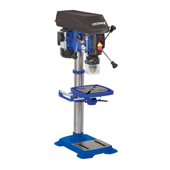
Page 8: Know Your Bench Drill Press
V. Know your drill press Fig. 1 A Digital speed readout H Housing cover P Bevel scale B Large ON/OFF switch Column Q Laser line ON/OFF switch C Depth scale J Rack R LED work light switch D Chuck K Crank handle S Extension wing with integrated E Table L Column support... -
Page 9: Assembly And Adjustments
VI. Assembly and adjustments UNPACKING AND CLEANING Unpack the bench drill press and all its parts, and compare against the list below. Do not discard the carton or any packaging until the bench drill press is completely assembled. To protect the bench drill press from moisture, a protective coating has been applied to the machined surfaces. - Page 10 VI. Assembly and adjustments ... continued ASSEMBLY The column assembly (column, column support, rack, rack collar, and table support bracket) must be attached to the base. The table and table support handles must be attached to the table support bracket. The motor housing must be attached to the column. WARNING: IF ANY PART IS MISSING OR DAMAGED, DO NOT PLUG THE BENCH DRILL PRESS IN UNTIL THE MISSING OR DAMAGED PART IS REPAIRED OR...
- Page 11 VI. Assembly and adjustments ... continued Drill press head to column (Fig. 5) Fig. 5 CAUTION: The drill press head is heavy. To avoid injury, two people should lift it into position. 1. Carefully lift the drill press head assembly (1) and position it over the column (2).
- Page 12 VI. Assembly and adjustments ... continued Mount the bench drill press (Fig. 8) Fig. 8 The bench drill press must be securely fastened through the mounting holes (1) to a stand or workbench with heavy-duty fasteners. This will prevent the bench drill press from tipping over, sliding, or walking during operation.
- Page 13 VI. Assembly and adjustments ... continued WARNING: DISCONNECT THE BENCH DRILL PRESS FROM THE POWER SOURCE BEFORE INSTALLING, ADJUSTING, OR REMOVING THE CHUCK. Fig. 10 To install the chuck (Fig. 10) 1. Inspect and clean the taper hole in the chuck (1) and the spindle (2).
- Page 14 VI. Assembly and adjustments ... continued ADJUSTMENTS Table adjustments Fig. 12 To raise or lower the table (Fig. 12) Loosen the support lock handle (1) and turn the crank handle (2) until the table is at the desired height. Tighten the table lock before drilling. To rotate the table (Fig.
- Page 15 VI. Assembly and adjustments ... continued To install drill bits (Fig. 15) Place the chuck key (1) into the side keyhole Fig. 15 of the chuck (2), meshing the key with the gear teeth. Turn the chuck key counter-clockwise to open the chuck jaws (3).
- Page 16 VI. Assembly and adjustments ... continued Laser line (Fig. 17 and 18) WARNING: DO NOT STARE DIRECTLY AT THE LASER BEAM! A HAZARD MAY EXIST IF YOU DELIBERATELY STARE INTO THE BEAM, PLEASE OBSERVE ALL SAFETY RULES: THE LASER SHALL BE USED AND MAINTAINED IN ACCORDANCE WITH THE MANUFACTURER'S INSTRUCTIONS: •...
- Page 17 VI. Assembly and adjustments ... continued Spindle return spring (Fig. 19) Fig. 19 The spindle is equipped with an auto-return mechanism. The main components are a spring and a notched housing. The spring was properly adjusted at the factory and should not be readjusted unless absolutely necessary.
- Page 18 VI. Assembly and adjustments ... continued WARNING: DISCONNECT THE BENCH DRILL PRESS FROM THE POWER SOURCE BEFORE REPLACING THE BELT. To replace the belt (Fig. 21) Belt tension and bench drill press speed is Fig. 21 controlled by automatic adjustments made to the diameter of the front spindle when the drive handle is moved.
-
Page 19: Operation
VII. Operation Bench Drill Press ON/OFF switch (Fig. 23) Fig. 23 1. To turn the drill press ON, insert the yellow safety key (1) into the switch housing (2). As a safety feature, the switch cannot be turned ON without the safety key. 2. - Page 20 VII. Operation ... continued GENERAL DRILLING GUIDELINES WARNING: TO PREVENT THE WORKPIECE AND THE BACKUP MATERIAL FROM SLIPPING FROM YOUR HAND WHILE DRILLING, POSITION WORKPIECE AND BACKUP MATERIAL TO THE LEFT SIDE OF THE COLUMN. IF THE WORKPIECE AND THE BACKUP MATERIAL ARE NOT LONG ENOUGH TO REACH THE COLUMN, CLAMP WORKPIECE AND BACKUP MATERIAL TO THE TABLE.
- Page 21 VII. Operation ... continued Drilling an unmeasured blind hole (not all the way Fig. 26 through the workpiece) to a given depth can be done two ways: using the depth scale method or workpiece method. Depth scale method (Fig. 26) 1.
- Page 22 VII. Operation ... continued Drilling speeds Important factors when determining the best drilling speed: • Material type • Hole size • Drill bit or cutter type • Quality desired Smaller drill bits require greater speed than large drill bits. Softer materials require greater speed than harder materials.
- Page 23 VII. Operation ... continued Mechanical variable speed (Fig. 28) This is a variable speed bench drill press. To Fig. 28 increase or decrease the speed when operating, raise or lower the speed handle (1). Use the following table to determine the recommended speed for the drill size you are using and the type of material you are to drill.
-
Page 24: Maintenance
VIII. Maintenance WARNING: FOR YOUR OWN SAFETY, TURN THE SWITCH OFF AND REMOVE THE PLUG FROM THE POWER SUPPLY BEFORE MAINTAINING OR LUBRICATING THE BENCH DRILL PRESS. Vacuum sawdust or metal shavings that accumulates in and on the motor, pulley housing, table, and work surface. -
Page 25: Troubleshooting
IX. Troubleshooting PROBLEM PROBABLE CAUSE REMEDY Noisy operation. 1. Incorrect belt tension. • Adjust the belt tension. See "To replace the belt" in ADJUSTMENTS. 2. Dry spindle. • Lubricate the spindle. See MAINTENANCE section. 3. Loose spindle pulley. • Tighten the retaining nut on the pulley insert. 4. - Page 26 IX. Troubleshooting ... continued PROBLEM PROBABLE CAUSE REMEDY The workpiece splinters 1. No backup material under • Always use a backup material. See "Position on the underside. the workpiece. the table and workpiece" in OPERATION. The workpiece is 1. Not supported or clamped •...
-
Page 27: Replacement Parts
X. Replacement parts K15310 Explosive Drawing... - Page 28 X. Replacement parts ... continued K15310 PARTS LIST Description Description No. Part No. Part No. Base Tube-quill K15310-1 K15310-38 Support column Lock-depth bolt K15310-2 K15310-39 Hex.Bolt M10x30 Quill Gasket K15310-3 K15310-40 Hex.Screw M8x8 Ball Bearing 6201 K15310-4 K15310-41 Handlebar Assembly...
- Page 29 X. Replacement parts ... continued Description Description No. Part No. Part No. Ring-retaining Screw K15310-75 K15310-104 Spacer nut M5 K15310-76 K15310-105 Pulley Insert Self-tapping screw K15310-77 K15310-106 Screw K15310-78 K15310-107 Hex nut M12 Cord clamp K15310-79 K15310-108 Cap-spring Washer K15310-80...
Need help?
Do you have a question about the K15310 and is the answer not in the manual?
Questions and answers