
Related Manuals for Hatz Diesel 1B20V


Summary of Contents for Hatz Diesel 1B20V
- Page 1 Translation of the ORIGINAL INSTRUCTION BOOK 1B 20V 1B 30V 1B 40V 1B 40W 1B 50V 1B 50W 000043380277- ENG- 01.11- 0.1 Printed in Germany...
- Page 3 A new HATZ Diesel engine - working for you This engine is intended only for the purpose determined and tested by the manufacturer of the equipment in which it is installed. Using it in any other manner contravenes the intended purpose.
-
Page 4: Table Of Contents
Contents Page Page Important safety notes 5.3. Maintenance every 250 when operating the engine operating hours 5.3.1. Changing engine oil Description of the engine 5.3.2. Checking and adjusting valve clearances General notes 5.3.3. Cleaning the air cleaner zone 3.1. Technical data 5.3.4. -
Page 5: Important Safety Notes When Operating The Engine
Important safety notes when operating the engine HATZ diesel engines are efficient, strong and durable. For this reason they are frequently installed on equipment used for commercial purposes. The manufacturers of such equipment must observe any relevant equipment safety regulations when the engine forms part of an overall system. - Page 6 Important safety notes when operating the engine – The engine must be stopped before performing any maintenance, cleaning- or repair work. – Stop the engine before refilling the fuel tank. Never refuel near a naked flame or sparks which could start a fire. Don’t smoke. Don’t spill fuel. –...
-
Page 7: Description Of The Engine
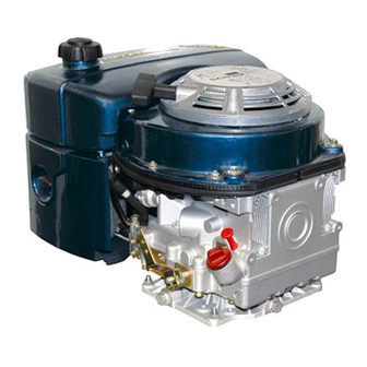
Description of the engine Fig 1 1 Fuel tank cap 9 Engine shutdown pin 2 Recoil starter 10 Speed control lever 3 Dry-type air cleaner 11 Oil filler pipe 4 Intake opening for cooling and 12 Oil filter combustion air 13 Oil drain plug 5 Voltage regulator 14 Dipstick... -
Page 8: General Notes
General notes 3.1. Technical data Type 1B20 V 1B30 V 1B40 V/ W 1B50 V/ W Design Air-cooled four-stroke diesel engine Combustion system Direct injection Number of cylinders Bore/stroke 69 / 65 80 / 69 88 / 76 93 / 76 Displacement Lubricating oil capacity l, approx. -
Page 9: Transport
3.2. Transport The permitted loads and elements on the speed adjusting lever and the A suspension lug „ 8“ is provided as engine shutdown pin should be observed as an standard equipment, so that the engine excess can lead to damage to the contacts and can be lifted safely, chap. -
Page 10: Operation
Operation 4.1. Before starting up for the first time Engines are normally supplied dry, i.e. not con- taining fuel or oil. 4.1.1. Engine oil Oil quality Qualified are all trademark oils which fulfil at least one of the following specifications: ACEA –... -
Page 11: Fuel
When adding oil or checking the oil level, the 4.1.2. Fuel engine must be horizontal. Stop the engine before refilling the fuel tank. Never refuel near a naked flame or sparks which could start a fire. Don’t smoke. Use only pure fuel and clean filling equipment. -
Page 12: Starting
At temperatures below 0 °C, winter-grade fuel should be used or paraffin added to the fuel well in advance. Paraffin content for: Lowest ambient temperature when Summer Winter starting, in °C fuel fuel 0 up to –10 20 % – –10 up to –15 30 % –... -
Page 13: Recoil Start For Versions Without Electric Starter
– Let the cable run back; in this way the entire length of the starting cable can be used to start the engine. – Devices which are not securely fastened should be restrained with the foot. Never use starting sprays ! 4.2.2. -
Page 14: Recoil Start For Versions With Electric Starter
Note: Note: If after several attempts of starting the exhaust In the case of engines with automatic electrical begins to emit white smoke, move the speed shutdown system (see next chapter), first control lever to the STOP position and pull the actuate the starter switch from position 0 to starting cable out slowly 5 times. - Page 15 – The battery charge telltale and oil pressure Fuel shut-off valve, stop solenoid warning must go out immediately after start- (additional equipment) ing. Indicator light „1“ is on when the engine is in operation; Fig. 15. – The engine temperature display „4“ (additional equipment) lights up if the temperature at the cylinder head becomes too high.
-
Page 16: Stopping The Engine
– As soon as the emergency start lever is in the Important ! starting position, the electric starter or recoil If the engine cuts out immediately after starting starter can be used; Chapter 4.2.2 and 4.2.3. or switches off by itself during operation, a The oil level must always be checked before an monitoring element in the automatic shutdown emergency start, as insufficient oil pressure... - Page 17 Note: Engines with a fixed lower idling speed cannot be switched off using the speed adjustment lever. See the paragraph entitled „Other ways of switching off the engine“. Other ways of switching off the engine 1. Fuel shut-off valve, stop solenoid (optional extra) –...
-
Page 18: Maintenance
Maintenance Only carry out maintenance work with the engine switched off. Observe all relevant laws and regulations governing the handling and disposal of used oil, filters and cleaning agents. Protect the starting key against unauthorised use. On engines with an electric starter, disconnect the battery’s negative terminal. When maintenance work has been completed, check that all tools have been removed from the engine and all protective guards fitted again. - Page 19 1B20: 0,20mm 1B27: 0,10mm 1B30: 0,10mm 1B40: 0,10mm 1B50: 0,10mm 0000 051 104 06 250h = 1h 500h Model without automatic valve clearance adjustment. AUTOM. 0000 052 502 02 250h = 1h 500h Model with automatic valve clearance adjustment. Depending whether the engine is equipped with On new or reconditioned engines, after the or without automatic valve clearance adjustment first 25 operating hours, always...
-
Page 20: Maintenance Every
Maintenance every 8 – 15 5.2. operating hours 5.2.1. Checking engine oil level To check the oil level, the engine must be standing level and be switched off. – Remove any dirt from the oil dipstick area. – Check air intake points „1“ for severe blockage due to leaves, heavy dust accumulation etc., and if necessary clean them. -
Page 21: Maintenance Every 250 Operating Hours
Maintenance every 250 5.3.2. Checking and adjusting valve 5.3. clearances operating hours Remark: 5.3.1. Changing engine oil Following steps are inapplicable in case equip- The engine must be standing level and be ment is with automatic tappet clearance com- switched off. pensation. - Page 22 – Remove any contamination adhering to the – Turn the crankshaft through 360° in the cover for the cylinder head. normal direction of rotation and align exactly to the OT-marking, Figure 27. – Remove screws „1“ and take off the cylinder head cover with gasket „2“.
-
Page 23: Cleaning The Air Cleaner Zone
5.3.3. Cleaning cooling air area 5.3.5. Cleaning the exhaust mesh inlet The engine must be switched off and Exhaust system components will cooled down before cleaning! naturally be hot and must not be touched while the engine is running or until it has cooled down after being stopped. - Page 24 Risk of injury! – Insert exhaust manifold with hoop „2“ into Wear protective gloves. hole, them pull outwards again so that the hoop is retained. – Eliminate deposited matter from the strainer insert using a suitable steel brush. – Tighten the hexagon nut fully. –...
-
Page 25: Maintenance Every 500 Operating Hours
Maintenance every 500 5.4. operating hours 5.4.1. Renewing fuel filter The maintenance intervals for the fuel pump filter are dependent upon the purity of the diesel oil being used and, if necessary, may have to be reduced to 250 hours. When working on the fuel system, do not expose it to naked flames;... - Page 26 – Remove the air cleaner cover. – On versions with a mechanical air cleaner service indicator, check the condition and cleanliness of valve plate „1“. – The filter cartridge should either be renewed or, depending upon the degree of contamina- tion, cleaned, or checked, as follows: Cleaning the filter cartridge Dry contamination...
-
Page 27: Maintenance Every 1000 Operating Hours
Important ! Maintenance every 1000 5.5. The pressure must not exceed 5 bar. operating hours 5.5.1. Cleaning the oil filter Persons handling compressed air must wear protective goggles. Never direct Cleaning of oil filter should be carried out the jet to animals, persons or yourself ! together with changing engine oil. - Page 28 – Remove oil filter from housing. – Check joint washer „1“ whether it is damage; replacement if necessary. – Coat packing rings „1“ and „2“ slightly with oil before assembly. – Use an air line to blow out oil filter dirt from the inside outwards.
-
Page 29: Servicing: Once A Year
5.6. Servicing: once a year 5.6.1. Draining the fuel tank When working on the fuel system, do not expose it to a naked flame; do not smoke. – Condensation forms due to temperature varia- tions at the lowest points of the fuel tank. The condensate must therefore be removed once a year as follows: –... -
Page 30: Malfunctions - Causes - Remedies
Malfunctions – causes and remedies Malfunctions Possible causes Remedy Chap. 6.1. Speed control lever in stop or Engine does not idle position. Move lever to START position. 4.2.1. start, or not imme- Engine shutdown pin in STOP Move to operating position by diately, but can be position. - Page 31 Malfunctions Possible causes Remedy Chap. At low Starting speed below 400 rpm: temperatures - Viscosity of oil too high. Change lubricating oil and add 5.3.1. oil of the correct viscosity class. 4.1.1. - Battery charge too low. Check the battery, if necessary contact a service station.
- Page 32 Malfunctions Possible causes Remedy Chap. 6.4. Fuel supply interrupted Engine cuts out of - Tank has run empty. Add fuel. 4.1.2. its own accord - Fuel filter blocked. Change fuel filter. 5.4.1. during operation. - Aeration outlet restricted at fuel tank seal. Ensure adequte tank venting.
- Page 33 Malfunctions Possible causes Remedy Chap. 6.6. Air cleaner contaminated. Clean or renew the air cleaner. 5.4.2. Engine output and speed fall, Valve clearances incorrect. Adjust valve clearances. 5.3.2. black smoke from exhaust. Injector not functioning. See workshop manual. 6.7. Too much lubricating oil in Drain off lubricating oil as far as Engine becomes engine.
-
Page 34: Work On The Electrical System
– Do not splash electrical device with water jet Work on the electrical or pressure jet during engine cleaning. system – When carrying out welding work on the en- gine or equipment, fit the earth clip of the welding equipment as close to the welding Batteries generate explosive gases. - Page 36 CALIFORNIA Proposition 65 Warning Diesel engine exhaust and some of its constituents are known to the State of California to cause cancer, birth defects, and other reproductive harm.
- Page 37 Technical Library http://engine.od.ua...
Need help?
Do you have a question about the 1B20V and is the answer not in the manual?
Questions and answers