Sign In
Upload
Manuals
Brands
NF Manuals
Amplifier
HVA4321
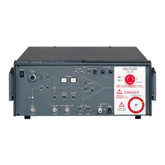
NF HVA4321 High Voltage Amplifier Manuals
Manuals and User Guides for NF HVA4321 High Voltage Amplifier. We have
1
NF HVA4321 High Voltage Amplifier manual available for free PDF download: Instruction Manual
NF HVA4321 Instruction Manual (152 pages)
Brand:
NF
| Category:
Amplifier
| Size: 4 MB
Table of Contents
Safety Precautions
6
Table of Contents
9
1 Overview
17
Features
19
Function Description and Block Diagram
21
Function Description
21
Block Diagram
21
Preparations before Use
23
Before Using the HVA4321
25
Table2-1. Accessories
25
Installation
26
Grounding and Power Supply Connection
27
Figure2-1. Check of Power off
27
Figure2-2. Check of Internal High Voltage DC Power off
27
Figure2-3. Inserting Power Cable Connector
28
Figure2-4. Using Conversion Connector
28
Figure2-5. Casing Ground Terminal
29
3 Nomenclature and Functions
31
Signal System
33
Internal DC Bias Signal Source
33
External Bias Signal Input
33
External Signal Input
34
Input Signal ON/OFF
34
Figure3-3. External Signal Input
34
Figure3-4. Signal ON/OFF Switch
34
Amplifier
36
Amplifier Operation Mode
36
Figure3-5. Operation Mode Switch
36
Amplifier Control
38
Figure3-6. Limiter and Response
38
Figure3-7. Operation of Voltage Limiter (1)
38
Figure3-8. Operation of Voltage Limiter (2)
38
Figure3-9. Operation of Current Limiter
39
Figure3-10. Response Function in Constant Voltage Mode
40
Figure3-11. Response Function in Constant Current Mode
40
Output
41
Figure3-13. Power Supply and Internal High Voltage DC Power
41
Figure3-14. Return Terminal
42
Monitor and Control Signal System
43
Monitor
43
Figure3-16. Status Signal Output
43
Control Signal System
44
Figure3-17. Remote/Local Settings
44
Figure3-18. Remote Control Input
44
Figure3-19. Remote Control Input Circuit
45
Table3-1. Logic of HIGH VOLTAGE POWER SUPPLY ON/OFF
45
Figure3-20. Remote Control of HIGH VOLTAGE POWER SUPPLY ON/OFF
46
Figure3-21. Remote Control of Signal System ON/OFF
46
Table3-2. Logic of Signal System ON/OFF Signal
46
Figure3-22. Remote Control of Signal ON/OFF
47
Table3-3. Logic of SIGNAL ON/OFF Signal
47
Figure3-23. Example of Status Contact Output
48
Table3-4. Status Contact Output Signal
48
Power Supply Items
49
Front Panel
51
Rear Panel
53
4 Operation Method
55
Operation Example in Constant Voltage Mode
57
Figure4-1. Constant Voltage Mode (Total Mode)
57
Figure4-2. Constant Voltage Mode (Load Mode)
58
Figure4-3. Internal High Voltage DC Power off
59
Figure4-4. Switch Settings
59
Panel Setting
59
Figure4-5. Output Mode Settings
60
Figure4-6. Local Settings
60
Figure4-7. Limiter Settings
61
Figure4-8. Current Monitor Mode Settings
61
Connection of Signal Source and Connection of Load
62
Figure4-10. Connection of External Signal Source Signal
62
Figure4-9. Response Settings
62
Figure4-11. Connection of Monitor
63
Figure4-12. Connection of Output Cable
63
Figure4-13. Power Supply
65
Power Supply and Internal High Voltage DC Power Supply
65
Figure4-14. Internal High Voltage DC Power on
66
Figure4-15. Using Internal DC Bias Signal
67
Signal Output and Adjustment
67
Figure4-16. Using External Oscillator
68
Figure4-17. Using External DC Bias Signal
68
Signal off
69
Operation Example in Constant Current Mode (Total)
70
Figure4-18. Total Mode
71
Figure4-19. Internal High Voltage DC Power off
72
Figure4-20. Switch Settings
72
Panel Setting
72
Figure4-21. Output Mode Settings
73
Figure4-22. Local Settings
73
Figure4-23. Limiter Settings
74
Figure4-24. Current Monitor Mode Settings
74
Connection of Signal Source and Connection of Load
75
Figure4-25. Response Settings
75
Figure4-26. Connection of External Signal Source Signal
75
Figure4-27. Connection of Monitor
76
Figure4-28. Connection of Output Cable
76
Figure4-29. Power Supply
78
Power Supply and Internal High Voltage DC Power Supply
78
Figure4-30. Internal High Voltage DC Power on
79
Figure4-31. Using Internal DC Bias Signal
80
Signal Output and Adjustment
80
Figure4-32. Using External Oscillator
81
Figure4-33. Using External DC Bias Signal
81
Signal off
82
Operation Example in Constant Current Mode (Load)
83
Figure4-34. Load Mode
84
Figure4-35. Internal High Voltage DC Power off
85
Figure4-36. Switch Settings
85
Panel Setting
85
Figure4-37. Output Mode Settings
86
Figure4-38. Local Settings
86
Figure4-39. Limiter Settings
87
Figure4-40. Current Monitor Mode Settings
87
Connection of Signal Source and Connection of Load
88
Figure4-41. Response Settings
88
Figure4-42. Connection of External Signal Source Signal
88
Figure4-43. Connection of Monitor
89
Figure4-44. Connection of Output Cable
89
Figure4-45. Power Supply
91
Power Supply and Internal High Voltage DC Power Supply
91
Figure4-46. Internal High Voltage DC Power on
92
Figure4-47. Using Internal DC Bias Signal
93
Signal Output and Adjustment
93
Figure4-48. Using External Oscillator
94
Figure4-49. Using External DC Bias Signal
94
Signal off
95
Operation Example in Constant Current + Constant Voltage Mode
96
Figure4-50. Constant Current Constant Voltage Mode (Total Mode)
97
Figure4-51. Constant Current Constant Voltage Mode (Load Mode)
97
Figure4-52. Internal High Voltage DC Power off
98
Figure4-53. Switch Settings
98
Panel Setting
98
Figure4-54. Output Mode Settings
99
Figure4-55. Local Settings
99
Figure4-56. Limiter Settings
100
Figure4-57. Current Monitor Mode Settings
100
Connection of Signal Source and Connection of Load
101
Figure4-58. Response Settings
101
Figure4-59. Connection of External Signal Source Signal
101
Figure4-60. Connection of Monitor
102
Figure4-61. Connection of Output Cable
103
Figure4-62. Power Supply
104
Power Supply and Internal High Voltage DC Power Supply
104
Figure4-63. Internal High Voltage DC Power on
105
Power Supply
105
Figure4-64. Using Internal DC Bias Signal
106
Signal Output and Adjustment
106
Figure4-65. Using External Oscillator
107
Figure4-66. Using External DC Bias Signal
107
Signal off
108
Change of Load and Power off
109
Change of Load
109
Figure4-67. Input Signal off
109
Figure4-68. Internal High Voltage Power Supply off
109
Figure4-69. Checking Items before Power off
110
Figure4-70. POWER off
110
Figure4-71. Removing High Voltage Cable
111
Power Supply off
112
Remote Control
113
Figure4-72. Remote Control
113
Figure4-73. Remote Control Switch
114
Panel Setting for Use of Remote Control
114
5 Representative Characteristics
115
Measuring Method
117
Figure5-1. Compensation of Probe
117
Figure5-2. Measuring Method of Output Voltage
117
Figure5-3. Measuring Method of Output Current
118
Characteristics in Constant Voltage Mode
119
Frequency Characteristics
119
Figure5-4. Frequency Characteristics in Constant Voltage Mode Without Load
119
Figure5-5. Frequency Characteristics in Constant Voltage Mode with Capacity Load
119
Step Response
120
Figure5-6. Step Response in Constant Voltage Mode Without Load
120
Figure5-7. Step Response in Constant Voltage Mode with 35 Pf Load
120
Characteristics in Constant Current Mode
121
Frequency Characteristics
121
Figure5-8. Frequency Characteristics in Constant Current (TOTAL) Mode
121
Figure5-9. Frequency Characteristics in Constant Current (LOAD) Mode
121
Step Response
122
Figure5-10. Step Response in Constant Current Mode with 1 Mωload
122
Characteristics in Constant Current and Constant Voltage Mode
123
Frequency Characteristics
123
Figure5-11. Frequency Characteristics in Constant Current (TOTAL) + Constant Voltage Mode
123
Figure5-12. Frequency Characteristics in Constant Current (LOAD) + Constant Voltage Mode
123
Characteristics of Voltage Monitor and Current Monitor
124
Frequency Characteristics
124
Figure5-13. Frequency Characteristics of Voltage Monitor
124
Figure5-14. Frequency Characteristics of Current Monitor
124
Others
125
Delay of Output Signal for Input Signal
125
Figure5-15. Delay of Input/Output Signal
125
Step Response Due to Difference of Amplitude
126
Figure5-16. Step Response in Constant Voltage Mode
126
6 Troubleshooting
127
When Suspecting a Fault
129
7 Maintenance
131
Daily Maintenance
133
Figure7-1. How to Remove Fan Cover
133
Inspection
134
When the Unit Is Not Used for a Long Time
134
Performance Test
135
Test of Constant Voltage Mode
135
Figure7-2. Check Method of Constant Voltage Mode
135
Test of Constant Current Mode
136
Figure7-3. Check Method of Constant Current Mode
136
8 Specification
137
Figure3-12. Output Area
137
Figure3-15. Monitor Output
137
Signal Area
139
Amplifier
140
Characteristics of Constant Voltage Mode
140
Figure8-1. Output Current
140
Figure8-2. Voltage and Current Range Allowed for Output
141
Characteristics of Constant Current Mode
142
Monitor Output
143
Output Area
143
Other Input/Output Signal
144
Others
145
Protection Circuit
145
General Items
146
Advertisement
Advertisement
Related Products
NF HSA4051
NF HSA4014
NF HSA4012
NF HSA4052
NF HSA42011
NF HSA42012
NF HSA42014
NF HSA42051
NF HSA42052
NF BA4825
NF Categories
Amplifier
Measuring Instruments
AC Power Distribution
Portable Generator
Power Supply
More NF Manuals
Login
Sign In
OR
Sign in with Facebook
Sign in with Google
Upload manual
Upload from disk
Upload from URL