Panasonic CS-VE9NKE Service Manual
Hide thumbs
Also See for CS-VE9NKE:
- Operating instructions manual (64 pages) ,
- Service manual (72 pages)
Table of Contents
Advertisement
This service information is designed for experienced repair technicians only and is not designed for use by the general public.
It does not contain warnings or cautions to advise non-technical individuals of potential dangers in attempting to service a product.
Products powered by electricity should be serviced or repaired only by experienced professional technicians. Any attempt to service
or repair the products dealt with in this service information by anyone else could result in serious injury or death.
In order to avoid frostbite, be assured of no refrigerant leakage during the installation or repairing of refrigerant circuit.
TABLE OF CONTENTS
1. Safety Precautions.............................................3
2. Specification .......................................................5
3. Features ............................................................11
4. Location of Controls and Components .........12
4.1
Indoor Unit..................................................12
4.2
Outdoor Unit ...............................................12
4.3
Remote Control ..........................................12
5. Dimensions .......................................................13
5.1
Indoor Unit and Remote Control ................13
5.2
Outdoor Unit ...............................................14
6. Refrigeration Cycle Diagram...........................15
7. Block Diagram ..................................................16
8. Wiring Connection Diagram............................17
8.1
Indoor Unit..................................................17
WARNING
PRECAUTION OF LOW TEMPERATURE
PAGE
9. Electronic Circuit Diagram ..............................19
10. Printed Circuit Board .......................................21
11. Installation Instruction.....................................24
12. Operation Control.............................................33
Indoor Unit
CS-VE9NKE
CS-VE12NKE
8.2
Outdoor Unit ...............................................18
9.1
Indoor Unit..................................................19
9.2
Outdoor Unit ...............................................20
10.1
Indoor Unit..................................................21
10.2
Outdoor Unit ...............................................23
11.1
Select the Best Location ............................24
11.2
Indoor Unit..................................................25
11.3
Outdoor Unit ...............................................30
12.1
Basic Function............................................33
12.2
Indoor Fan Motor Operation.......................35
12.3
Outdoor Fan Motor Operation ....................38
Order No: RAC1207001CE
Outdoor Unit
CU-VE9NKE
CU-VE12NKE
PAGE
Advertisement
Table of Contents

Subscribe to Our Youtube Channel
Related Manuals for Panasonic CS-VE9NKE


Summary of Contents for Panasonic CS-VE9NKE
-
Page 1: Table Of Contents
Order No: RAC1207001CE Indoor Unit Outdoor Unit CS-VE9NKE CU-VE9NKE CS-VE12NKE CU-VE12NKE WARNING This service information is designed for experienced repair technicians only and is not designed for use by the general public. It does not contain warnings or cautions to advise non-technical individuals of potential dangers in attempting to service a product. - Page 2 12.4 Airflow Direction..........38 12.5 Quiet Operation ..........41 12.6 Powerful Mode Operation......41 12.7 Timer Control..........41 12.8 Auto Restart Control ........42 12.9 Indication Panel ..........42 12.10 nanoe-G Operation........43 12.11 +8/10°C Heat Operation ......45 12.12 AUTO COMFORT and ECONAVI Operation............46 13. Protection Control..........53 13.1 Protection Control for All Operations..53 13.2 Protection Control for Cooling and Soft...
-
Page 3: Safety Precautions
1. Safety Precautions Read the following “SAFETY PRECAUTIONS” carefully before perform any servicing. Electrical work must be installed or serviced by a licensed electrician. Be sure to use the correct rating of the power plug and main circuit for the model installed. ... - Page 4 WARNING 19. During installation, install the refrigerant piping properly before run the compressor. (Operation of compressor without fixing refrigeration piping and valves at opened condition will caused suck-in of air, abnormal high pressure in refrigeration cycle and result in explosion, injury etc). 20.
-
Page 5: Specification
2. Specification Indoor CS-VE9NKE Model Outdoor CU-VE9NKE Performance Test Condition EN 14511 Phase, Hz Single, 50 Power Supply Min. Mid. Max. Min. Mid. Max. Capacity 0.60 2.50 3.00 0.60 2.50 3.00 Running Current — — — — Input Power Annual Consumption —... - Page 6 Indoor CS-VE9NKE Model Outdoor CU-VE9NKE Type Cross-flow fan Material AS+GF Resin Motor Type PWM (8-poles) Input Power 23.6 Output Power Cool Heat Cool Heat Cool Speed Heat Cool 1110 Heat 1110 Cool 1190 Heat 1110 Type Propeller Fan + Flat piece...
- Page 7 Indoor CS-VE9NKE Model Outdoor CU-VE9NKE Inner Diameter 16.7 Drain Hose Length Fin Material Aluminium (Pre Coat) Indoor Heat Exchanger 26.5 + 17 Fin Material Aluminium (Pre Coat) Fin Type Corrugated Fin Outdoor Heat Row x Stage x FPI 2 × 32 × 19.5 Exchanger 871.6 ×...
- Page 8 Indoor CS-VE12NKE Model Outdoor CU-VE12NKE Performance Test Condition EN 14511 Phase, Hz Single, 50 Power Supply Min. Mid. Max. Min. Mid. Max. Capacity 0.60 3.50 4.00 0.60 3.50 4.00 Running Current — — — — Input Power 1.10k 1.10k Annual Consumption —...
- Page 9 Indoor CS-VE12NKE Model Outdoor CU-VE12NKE Type Cross-flow fan Material AS+GF Resin Motor Type PWM (8-poles) Input Power 28.5 Output Power Cool Heat Cool Heat Cool 1040 Speed Heat 1050 Cool 1190 Heat 1140 Cool 1270 Heat 1140 Type Propeller Fan + Flat piece Material Motor Type DC Brushless (8-poles)
- Page 10 Indoor CS-VE12NKE Model Outdoor CU-VE12NKE Inner Diameter 16.7 Drain Hose Length Fin Material Aluminium (Pre Coat) Indoor Heat Exchanger 26.5 + 17 Fin Material Aluminium (Pre Coat) Fin Type Corrugated Fin Outdoor Heat Exchanger Row x Stage x FPI 2 × 32 × 19.5 871.6 ×...
-
Page 11: Features
3. Features Inverter Technology Wider output power range Energy saving Quick Cooling Quick Heating More precise temperature control Environment Protection Non-ozone depletion substances refrigerant (R410A) Long Installation Piping Long piping up to 15 meters during single split connection only ... -
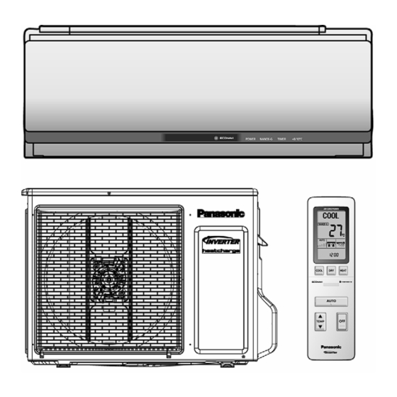
Page 12: Location Of Controls And Components
4. Location of Controls and Components Indoor Unit Outdoor Unit Remote Control... -
Page 13: Dimensions
5. Dimensions Indoor Unit and Remote Control... -
Page 14: Outdoor Unit
Outdoor Unit... -
Page 15: Refrigeration Cycle Diagram
6. Refrigeration Cycle Diagram... -
Page 16: Block Diagram
7. Block Diagram... -
Page 17: Wiring Connection Diagram
8. Wiring Connection Diagram Indoor Unit... -
Page 18: Outdoor Unit
Outdoor Unit... -
Page 19: Electronic Circuit Diagram
9. Electronic Circuit Diagram Indoor Unit... -
Page 20: Outdoor Unit
Outdoor Unit... -
Page 21: Printed Circuit Board
10. Printed Circuit Board 10.1 Indoor Unit 10.1.1 Main Printed Circuit Board... - Page 22 10.1.2 Printed Circuit Board...
-
Page 23: Outdoor Unit
10.2 Outdoor Unit 10.2.1 Main Printed Circuit Board... -
Page 24: Installation Instruction
11. Installation Instruction 11.1 Select the Best Location 11.1.3 Indoor/Outdoor Unit Installation 11.1.1 Indoor Unit Diagram Do not install the unit in excessive oil fume area such as kitchen, workshop and etc. There should not be any heat source or steam near the unit. -
Page 25: Indoor Unit
11.2 Indoor Unit 11.2.1 How to Fix Installation Plate The mounting wall shall be strong and solid enough to prevent it from the vibration. The center of the installation plate should be at more than 495 mm at right and left of the wall. The distance from installation plate edge to ceiling should more than 80 mm. - Page 26 11.2.3 Indoor Unit Installation 11.2.3.1 For the Right Rear Piping 11.2.3.2 For the Right and Right Bottom Piping 11.2.3.3 For the Embedded Piping (This can be used for left rear piping and bottom piping also.)
-
Page 28: Connect The Cable To The Indoor Unit
11.2.4 Connect the Cable to the Indoor Unit The inside and outside connection cable can be connected without removing the front grille. Connection cable between indoor unit and outdoor unit shall be approved polychloroprene sheathed 4 x 1.5 flexible cord, type designation 245 IEC 57 or heavier cord. Bind all the indoor and outdoor connection cable with tape and route the connection cable via the escapement. - Page 29 11.2.5 Wire Stripping and Connecting Requirement 11.2.6 Cutting and Flaring the Piping Please cut using pipe cutter and then remove the burrs. Remove the burrs by using reamer. If burrs is not removed, gas leakage may be caused. Turn the piping end down to avoid the metal powder entering the pipe. Please make flare after inserting the flare nut onto the copper pipes.
-
Page 30: Outdoor Unit
11.3 Outdoor Unit 11.3.1 Install the Outdoor Unit After selecting the best location, start installation according to Indoor/Outdoor Unit Installation Diagram. Install at least 3 cm above the ground. Do not install the unit on the floor. Fix the unit on concrete or rigid frame firmly and horizontally by bolt (ø10 mm). -
Page 31: Evacuation Of The Equipment
11.3.3 Evacuation of the Equipment WHEN INSTALLING AN AIR CONDITIONER, BE SURE TO EVACUATE THE AIR INSIDE THE INDOOR UNIT AND PIPES in the following procedure. Connect a charging hose with a push pin to the Low side of a charging set and the service port of the 3-way valve. -
Page 32: Connect The Cable To The Outdoor Unit
11.3.4 Connect the Cable to the Outdoor Unit Remove the control board cover from the unit by loosening the screw. Connection cable between indoor unit and outdoor unit shall be approved polychloroprene sheathed 4 x 1 .5 flexible cord, type designation 245 IEC 57 or heavier cord. -
Page 33: Operation Control
12. Operation Control 12.1 Basic Function Inverter control, which equipped with a microcomputer in determining the most suitable operating mode as time passes, automatically adjusts output power for maximum comfort always. In order to achieve the suitable operating mode, the microcomputer maintains the set temperature by measuring the temperature of the environment and performing temperature shifting. -
Page 34: Heating Operation
12.1.4 Heating Operation 12.1.4.1 Thermostat Control Compressor is OFF when Intake Air Temperature - Internal Setting Temperature > +2.0°C continue for 3 minutes. Compressor is ON after waiting for 3 minutes, if the Intake Air Temperature - Internal Setting Temperature < Compressor OFF point. -
Page 35: Indoor Fan Motor Operation
12.2 Indoor Fan Motor Operation 12.2.1 CS-VE9NKE Indicates the changeable range using the remote control Stop SSLo Quiet Lo 1100 ~ Fan speed: Manual 1180 Outside temperature is below 35°C or Neuro is Outside temperature is 35°C or higher Normal (with programmed air) stable. - Page 36 (1) When the area control is in operation, the minimum rotation speed is limited as outlined below depending on the human position area. Same as the fan speed in the powerful mode. When the airflow is stable, the minimum rotation speed is limited to COOL &...
- Page 37 12.2.2 CS-VE12NKE Indicates the changeable range using the remote control Stop SSLo Quiet Lo 1100 ~ Fan speed: Manual 1010 1190 Outside temperature is below 35°C or Neuro is Outside temperature is 35°C or higher Normal (with programmed air) stable. and Neuro is unstable.
-
Page 38: Outdoor Fan Motor Operation
(1) When the area control is in operation, the minimum rotation speed is limited as outlined below depending on the human position area. Same as the fan speed in the powerful mode. When the airflow is stable, the minimum rotation speed is limited to COOL &... -
Page 39: Vertical Airflow
12.4.1 Vertical Airflow Vertical Airflow Direction Louver Airflow direction: Auto Airflow direction: Sensor Normal Powerful Long Manual Normal AUTO According to each mode Discharge temperature 35° is high. Horizontal airflow 3.6kW or below: 60° direction (Slightly upward when there is no airflow When “Front, Spot or towards feet.) 1-4: Preset... - Page 40 12.4.2 Horizontal Airflow Automatic horizontal airflow direction can be set using remote control; the vane swings left and right within the angles as stated below. Left vane/right vane During Manual Setting At air-conditioning Area During Auto Setting Middle Setting Right Setting Left Setting Condition...
-
Page 41: Quiet Operation
12.5 Quiet Operation Purpose To provide quiet cooling operation compare to normal operation. Control condition Quiet operation start condition When “QUIET” button at remote control is pressed. Quiet operation stop condition When one of the following conditions is satisfied, quiet operation stops: ... -
Page 42: Auto Restart Control
12.7.3 Sleep Timer Sleep operation is performed according to the delay OFF time (0.5, 1, 2, 3, 5, 7 or 9 hr) and provide comfortable environment by shifting set temperature. Heating Cooling, Dry *5am *4am * According to remote control clock Temperature Shift Status 1 Status 2... -
Page 43: Nanoe-G Operation
12.10 nanoe-G Operation This operation provides clean air by producing great amount of negative ions and distribute through the discharge airflow to capture or deactivate molds, bacteria or viruses. nanoe-G ON/OFF condition Priority Item Output “No NANOE-G” is selected during model selection. During Demo mode Two-way communications on remote control NANOE-G connector open... - Page 44 Remote Control Receiving Sound Normal Operation nanoe-G Operation : Beep Nanoe-G Operation Normal Operation : Beep Stop nanoe-G individual Operation : Beep Nanoe-G individual Operation Stop : Long Beep Power failure During nanoe-G individual operation, if power failure occurs, after power resumes, nanoe-G individual operation resumes immediately.
-
Page 45: 8/10°C Heat Operation
12.11 +8/10°C Heat Operation +8/10°C Heat operation provides heating at low setting temperature in unoccupied houses during winter for the purpose of protecting equipments or housing appliances which may be destroyed by the extreme cold weather. This operation can be ON by pressing the +8/10°C heat button on the remote control. ... -
Page 46: Auto Comfort And Econavi Operation
12.12 AUTO COMFORT and ECONAVI Operation Area of human availability, activity level and absent is judged based on pulses by using 2 infrared sensors. The internal setting temperature shift, fan speed and horizontal airflow direction are adjusted in order to provide comfort environment while maintain the energy saving level. - Page 47 12.12.1.1 Signal Detection Presumption flow of human position. Detection outline. 12.12.1.2 Information Log The signal from Infrared sensor will be log to human activity database for further analysis. 12.12.1.3 Human Position Analysis According to Area of Living, frequency of activity, the system will analyze the human position away from the indoor unit.
- Page 48 12.12.1.6 Area of Living Classification Judgment The system is able to judge area of living according to human activity database, classified as following: (Zone I ) Living Area - In front of television, dining table, etc. (Zone II) Walkway - Human detection is relatively less. (Zone III) Non-Living Area - Near windows, wall, etc.
-
Page 49: Demo Mode
12.12.2.1 Demo Mode The air conditioner starts the operation in the Demo mode as described below when 2 minutes have elapsed after the protection control was started subsequent to the confirmation of communication error. (At this time, a strong warning sound is emitted for 3 minutes if the test run memory is “incomplete”.) Condition to stop the mode The operation is stopped by turning off the air conditioner on the remote control or pressing the EMERGENCY OPERATON switch during the Demo mode. - Page 50 Descriptions of the mode Every time the signal for infrared sensor check is received, the fixed detection is performed at a different human activity sensor angle. The result is displayed on LED every 3 seconds. Operation mode OFF (Cleaning is also stopped) Panel Ordinary operating position (It opens even if the mode signal received is “OFF”) Every time the signal for infrared sensor check is received, the position is shifted in the sequence of...
- Page 51 12.12.3.2 Judge Sunlight Intensity Based on sunlight sensor output voltage, the sunlight intensity value will be computed and logged to sunlight intensity database. The sunlight sensor sensitivity could be adjusted: 12.12.3.3 Judge Ambient Condition According to sunlight intensity over a period of time, the system will analyze the ambient condition is sunny, cloudy or night.
- Page 52 12.12.3.5 Sunlight Sensor Check Mode Operation details The sunlight sensor check mode will be operated for 5 minutes. During check mode, the ON and OFF timer will be memorized but it operation be ignored. During check mode, if the sunlight sensor check code is retransmitted, the 5 minutes counter will be reset. During check mode, if sunlight sensor detected the sunlight intensity value above minimum level, the ECONAVI indicator turns ON.
-
Page 53: Protection Control
13. Protection Control 13.1 Protection Control for All Operations 13.1.1 Restart Control (Time Delay Safety Control) The Compressor will not turn on within 3 minutes from the moment operation stops, although the unit is turned on again by pressing OFF/ON button at remote control within this period. ... - Page 54 13.1.3 IPM (Power Transistor) Prevention Control Overheating Prevention Control When the IPM temperature rises to 120°C, compressor operation will stop immediately. Compressor operation restarts after 3 minutes the temperature decreases to 110°C. If this condition repeats continuously 4 times within 20 minutes, timer LED will be blinking (“F96” is indicated). ...
-
Page 55: Protection Control For Cooling And Soft Dry Operation
13.1.8 4-Way Valve Operation Detection Control (Switching Abnormality between Cooling and Heating) When indoor heat exchanger exceeds 45°C (Cooling operation) or 0°C (Heating and Deice operation) in 4 minutes or 3 minutes (Deice operation) after compressor start, compressor will stopped. ... -
Page 56: Protection Control For Heating Operation
13.2.5 Dew Prevention Control 1 To prevent dew formation at indoor unit discharge area. This control will be activated if: Outdoor air temperature and Indoor pipe temperature judgment by microcontroller is fulfilled. When Cooling or Dry mode is operated more than 20 minutes or more. ... - Page 57 13.3.4 Low Temperature Compressor Oil Return Control In heating operation, if the outdoor temperature falls below -10°C when compressor starts, the compressor frequency will be regulated up to 600 seconds. 13.3.5 Cold Draught Prevention Control When indoor pipe temperature is low, cold draught operation starts where indoor fan speed will be reduced. 13.3.6 Deice Operation ...
- Page 58 Non-stop heating deice operation is prohibited when any of the following condition is met Protection control that limit capacity. Heat charge temperature sensor abnormal. Heat charge cycle abnormal. Outdoor pipe temperature sensor 2 abnormal. The outdoor temperature range falls under -30°C. ...
-
Page 59: Servicing Mode
14. Servicing Mode 14.1 Auto OFF/ON Button AUTO OPERATION MODE The Auto operation will be activated immediately once the Auto OFF/ON button is pressed. This operation can be used to operate air conditioner with limited function if remote control is misplaced or malfunction. TEST RUN OPERATION (FOR PUMP DOWN/SERVICING PURPOSE) The Test Run operation will be activated if the Auto OFF/ON button is pressed continuously for more than 5 seconds. -
Page 60: Remote Control Button
PREFERENCE SETTING MODE Individual Mode Each mode is cancelled if no operation is performed for 5 minutes or any code other than the diagnosis code is received from the remote control. 14.2 Remote Control Button 14.2.1 RESET To restore the unit’s setting to factory default. Press once to restore the unit’s setting. -
Page 61: Troubleshooting Guide
15. Troubleshooting Guide 15.1 Refrigeration Cycle System In order to diagnose malfunctions, make sure that there are no Normal Pressure and Outlet Air Temperature (Standard) electrical problems before inspecting the refrigeration cycle. Gas Pressure Outlet air Temperature Such problems include insufficient insulation, problem with the (kg/cm (°C) power source, malfunction of a compressor and a fan. - Page 62 15.1.1 Relationship between the Condition of the Air Conditioner and Pressure and Electric Current Cooling Mode Heating Mode Condition of the Electric current Electric current air conditioner Low Pressure High Pressure Low Pressure High Pressure during operation during operation Insufficient refrigerant ...
-
Page 63: Breakdown Self Diagnosis Function
15.2 Breakdown Self Diagnosis Function 15.2.1 Self Diagnosis Function (Three Digits Alphanumeric Code) Once abnormality has occurred during operation, the unit will stop its operation and Timer LED blinks. In case of abnormality which does not affect the refrigeration cycle, the operation will not stop but the Timer LED will blinks. ... -
Page 64: Self Diagnosis Functions And Points Of Diagnosis
15.3 Self Diagnosis Functions and Points of Diagnosis [List of Diagnosis Method] Main Areas to be Code Name of Diagnosis Descriptions on Diagnosis Diagnosed Codes for the commencement of — — — self diagnosis No memory of error — — code Indoor/outdoor When the indoor/outdoor communication failed for 15 seconds or more, the power relay... - Page 65 Outdoor unit heat Outdoor unit heat This error code is displayed when the detected temperature of the outdoor temperature exchanger sensor 2 is below -58°C or 107°C or higher for 5 consecutive seconds. exchanger temperature sensor 2 <Points of diagnosis> temperature error 1.
- Page 66 Indoor unit When the temperature of the indoor unit heat exchanger temperature sensor exceeds Dirt on air filter overpressure 60°C during the heating operation, this diagnosis code is stored in the memory and the Short-circuit of protection compressor stops operation. It resumes operation after 180 seconds if the temperature indoor unit is below 60°C.
- Page 67 Outdoor unit control Compressor rotation If the rotation of the compressor does not synchronize with the control signal, this error diagnosis code is stored in the memory and the compressor stops. It resumes operation board after 180 seconds. The error code is displayed if this error is detected four times within ...
-
Page 68: Self-Diagnosis Method
15.4 Self-diagnosis Method 15.4.1 H11 (Indoor/Outdoor Communication Error) Troubleshooting... - Page 69 15.4.2 H14 (Indoor Unit Intake Air Temperature Sensor Error) Troubleshooting...
- Page 70 15.4.3 H15 (Compressor Temperature Sensor Error) 15.4.4 H23 (Indoor Unit Heat Exchanger Temperature Sensor Error) 15.4.5 H27 (Outdoor Unit Temperature Sensor) 15.4.6 H28 (Outdoor Unit Heat Exchanger Temperature Sensor 1 Error) 15.4.7 H29 (Outdoor Unit Heat Exchanger Temperature Sensor 2 Error)
- Page 71 15.4.8 H53 (Heat Storage Tank Temperature Sensor Error) Troubleshooting...
- Page 72 15.4.9 H16 (Outdoor Unit CT Disconnection Error) Troubleshooting...
- Page 73 15.4.10 H19 (Indoor Unit Fan Motor Lock Error) Troubleshooting...
- Page 74 15.4.11 H33 (Connection Error of the Models with Different Voltage Power Supply) Troubleshooting...
- Page 75 15.4.12 H38 (Brand not Corresponding) Troubleshooting...
- Page 76 15.4.13 H50 (Ventilation Fan Motor Error) Troubleshooting...
- Page 77 15.4.14 H51 (Filter Cleaning Nozzle Lock Error) Troubleshooting...
- Page 78 15.4.15 H59 (Infrared Sensor Error) Troubleshooting...
- Page 79 15.4.16 H67 (NANOE Error) Troubleshooting...
- Page 80 15.4.17 H70 (Sunlight Sensor Error) Troubleshooting...
- Page 81 15.4.18 H96 (2- and 3-Way Valve Opening Failure Check) Troubleshooting...
- Page 82 15.4.19 H97 (Outdoor Unit Fan Motor Lock Error) Troubleshooting...
- Page 83 15.4.20 H98 (Indoor Unit Overpressure Protection) Troubleshooting...
- Page 84 15.4.21 H99 (Indoor Unit Heat Exchanger Freezing Protection (Error Code is to be Stored in the Memory only)) Troubleshooting...
- Page 85 15.4.22 F11 (Cooling-Heating Switching Error) Troubleshooting...
- Page 86 15.4.23 F16 (Cooling-Dry Switching Error) Troubleshooting...
- Page 87 15.4.24 F19 (Heat Storage Cycle Error) Troubleshooting...
- Page 88 15.4.25 F90 (PFC Protection) Troubleshooting...
- Page 89 15.4.26 F91 (Refrigeration Cycle Error) Troubleshooting...
- Page 90 15.4.27 F93 (Compressor Rotation Error) Troubleshooting...
- Page 91 15.4.28 F95 (Overpressure Protection in Case of Cooling Error) Troubleshooting...
- Page 92 15.4.29 F96 (Transistor Module Over-temperature Protection) Troubleshooting...
- Page 93 15.4.30 F97 (Compressor Over-temperature Protection) Troubleshooting...
- Page 94 15.4.31 F98 (Total Current Protection Control) Troubleshooting...
- Page 95 15.4.32 F99 (DC Peak Operation Error) Troubleshooting...
-
Page 96: Disassembly And Assembly Instructions
16. Disassembly and Assembly Instructions 16.1 Points of Disassembly (Indoor Unit) Be sure to disconnect the power plug from the outlet before disassembly or repair of the unit. Failure to observe this warning could result in electric shock. Be very careful not to touch the live parts when performing a repair work which requires power supply or Disconnect the power plug inspecting the circuit. - Page 97 16.1.3 Removing the Front Grille (Right) and Front Grille (Left) Perform “16.1.1 Removing the Front Panel”. Open the vertical airflow direction louver slowly. Remove the fixing screw (1 piece) of the indoor/outdoor unit transmission wire cover and leave the cover open.
- Page 98 16.1.4 Removing the Control Board Box Perform “16.1.1 Removing the Front Panel”. Perform “16.1.3 Removing the Front Grille (Right) and Front Grille (Left)”. Note on disassembly: When removing only the control board box, remove the front grille (right) only. Remove the electrical component cover (front) on the right side of the control board box.
- Page 99 Disconnect the connectors and terminals. Connectors CN-TH2 (green) ・・・・・ Indoor intake air temperature sensor No. 1 CN-DISP (white) ・・・・・ Control board (human sensor unit, signal receptor and indicator) No. 2 CN-FM (white) ・・・・・ Fan motor No. 3 CN-TH1 (yellow) ・・・・・ Indoor heat exchanger temperature sensor No. 4 CN-STM1 (green) ・・・・・...
- Page 100 Remove the earth wire screw (1 piece) and disconnect the indoor/outdoor connection wires as well as the connector for the white wire connected to the terminal block. Then, remove the control board box. Note on assembly: About lead wire arrangement during assembly ...
- Page 101 Disengage the tabs (5 locations) which fix the control board and then remove the control board. 16.1.6 Removing the Control Board (Emergency Operation Switch and Buzzer) Perform “16.1.1 Removing the Front Panel”. Perform “16.1.3 Removing the Front Grille (Right) and Front Grille (Left)”. ...
- Page 102 16.1.7 Removing the Human and Object Sensor of the Control Board (Indicator and Signal Receptor) Perform “16.1.1 Removing the Front Panel”. Perform “16.1.3 Removing the Front Grille (Right) and Front Grille (Left)”. Disengage the tabs (2 locations) on both sides of the indicator panel. Then, remove the indicator panel. Flip the indicator panel and remove the screws (2 pieces).
- Page 103 Disconnect the connector CNSTM4 (blue) connected to the control board. How to remove the control board (signal receptor) Disconnect the connectors (3 locations) and disengage the tabs (3 locations) on the control board (signal receptor). Then, remove the control board (signal receptor). ...
- Page 104 16.1.8 Removing the Air Filter Frame (Auto Cleaner) Perform “16.1.1 Removing the Front Panel”. Perform “16.1.2 Removing the Air Filters”. Note on disassembly: The air filter frame can be removed without removing the air filters. Nevertheless, be sure to remove the air filters because the top portion of the air filters may get stuck while reattaching the air filter frame.
- Page 105 16.1.9 Removing the Vertical Airflow Direction Louver How to remove the lower louver of the vertical airflow direction louver Open the lower louver. The back side of the lower louver is designed as follows: left – inserting type; center – hook engaging type; and right –...
- Page 106 16.1.10 Removing the Blowout Grille Perform “16.1.1 Removing the Front Panel”. Perform “16.1.2 Removing the Air Filters”. Perform “16.1.3 Removing the Front Grille (Right) and Front Grille (Left)”. Perform “16.1.4 Removing the Control Board Box”. Perform “16.1.8 Removing the Air Filter Frame (Auto Cleaner)”. Remove the screws (1 piece each on right and left) located at the bottom side of the blowout grille.
- Page 107 16.1.11 Removing the Drive Motor of the Vertical Airflow Direction Louver (Upper and Lower Louvers) Perform “16.1.1 Removing the Front Panel”. Perform “16.1.2 Removing the Air Filters”. Perform “16.1.3 Removing the Front Grille (Right) and Front Grille (Left)”. Perform “16.1.4 Removing the Control Board Box”. Perform “16.1.8 Removing the Air Filter Frame (Auto Cleaner)”.
- Page 108 Remove the horizontal louver (left) drive motor. Remove the drive motor fixing screw (1 piece) on the right side of the blowout grille. Push the drive motor fixing tab (1 location) towards the direction indicated by the arrow to disengage it. 10 Release the lever from the horizontal louver and remove the drive motor.
- Page 109 Loosen the fixing screw (1 screw) which fixes the cross flow fan to the indoor motor. Pull out the cross flow fan while lifting up the left side of the heat exchanger. 10 Remove the screws (3 pieces) of the indoor motor cover and pull out the indoor motor together with the cover to the right side to remove it.
-
Page 110: Points Of Disassembly (Outdoor Unit)
16.2 Points of Disassembly (Outdoor Unit) The electrical components of the outdoor unit are under high voltage by the operation of the booster capacitor. Fully discharge the capacitor before commencing a repair work. Failure to observe this warning could result in electric shock. CAUTION: HIGH VOLTAGE 16.2.1 Removing the Outer Top Panel and Outer Front Panel Remove the screws of the outer top panel. - Page 111 Disengage the tabs on the outer front panel (3 locations on the left side and 1 location on the right side). Remove the outer front panel while pulling it slightly up. 16.2.2 Removing the Electrical Component Covers (2 & 3-way valve Cover and Terminal Plate Cover) Remove the screw (1 piece) of the electrical component cover (2 &...
- Page 112 16.2.3 Removing the Power-Supply Box Perform “16.2.1 Removing the Outer Top Panel and Outer Front Panel”. Perform “16.2.2 Removing the Electrical Component Covers (2 & 3-way valve Cover and Terminal Plate Cover)”. Disengage 4 tabs of the electrical component cover (the top cover of the control board) (2 locations each on the right and left sides).
- Page 113 Disconnect the connector of the indoor/outdoor connection wires (red, white and black) and remove the fixing screw of the earth wire (green). Remove the screw (1 piece) which fixes the power-supply box to the outer side panel (right). Pull the outer side panel (right) towards you while pulling up the fixing tab (1 location) of the powersupply box to disengage the tab.
- Page 114 16.2.5 Removing the Propeller Fan and Outdoor Motor Perform “16.2.1 Removing the Outer Top Panel and Outer Front Panel”. Disengage 4 tabs of the electrical component cover (the top cover of the control board) (2 locations each on the right and left sides). Remove the electrical component cover (the top cover of the control board). Remove the fixing screw (1 piece) of the power-supply box.
- Page 115 Loosen the fixing screws (4 pieces) of the outdoor motor and remove the outdoor motor. Notes on assembly: When assembling the propeller fan and outdoor motor, the alignment mark located in the center part of the propeller fan should be aligned with the slit in the shaft of the outdoor motor. 16.2.6 Removing the Outer Side Panel (Right) Perform “16.2.1 Removing the Outer Top Panel and Outer Front Panel”.
- Page 116 Pull the outer side panel (right) towards you while pulling up the fixing tab (1 location) of the power-supply box to disengage the tab. Remove the fixing screws (5 pieces) of the outer side panel (right) and remove the outer side panel (right). ...
- Page 117 16.2.7 Removing the Compressor and Heat Storage Tank Perform “16.2.1 Removing the Outer Top Panel and Outer Front Panel”. Perform “16.2.2 Removing the Electrical Component Covers (2 & 3-way valve Cover and Terminal Plate Cover)”. Perform “16.2.3 Removing the Power-Supply Box”. Perform “16.2.6 Removing the Outer Side Panel (Right)”.
- Page 118 Remove the acoustic insulation material and then remove the nuts which fix the compressor (2 locations). (The heat storage tank is attached to the compressor.) Note on disassembly: Use a box wrench to remove the nut located on the right side from the front view. Remove the welded parts (4 locations).
- Page 119 Remove the compressor and heat storage tank. Cut the bands (2 locations) which fix the compressor to the heat storage tank. Remove the clamp and separate the compressor and heat storage tank. Note on disassembly: Remove the heat storage tank sensor when replacing the heat storage tank. 16.2.8 Heat Charger () Replacement Procedure 16.2.8.1 Preparation...
- Page 120 Cut off the band (small) for holding soundproof board and heat charger. Remove 4 screws (see figure) and slide soundproof board towards to propeller fan side to remove. Remove soundproof material at upper compressor. Remove discharge pipe sensor. Remove terminal cover from the compressor. 10 Remove 3 lead wires from compressor terminal.
- Page 121 16.2.8.3 Process 2 (Removing Brazing Point) Removing butyl tape from piping prior to removing the brazing point. Caution Protection from the brazing flame should be considered during replacing the parts. Firstly disconnect the pipe which entering to heat charger, discharging from heat charger, compressor suction and the discharging pipes.
- Page 122 16.2.8.5 Replacement of Heat Charger Exchange with the new heat charger. 16.2.8.6 Stick Heat Transferring Sheet and Fix the Heat Charger on the Compressor by Band Peel-off the yellow film from new heat transferring sheet, and stick it on compressor body. Then peel off transparent film for attaching heat charger.
- Page 123 16.2.8.7 Fix-back Compressor and Connect the Tubes Set compressor and heat charger block to the original position. Tighten 2 mounting nuts of compressor by using wrench. Braze-back the tubes you dismantled. Caution Protection from the brazing flame should be considered during brazing-back the parts, too. After brazing tubes, use cooling rag (wet towel) to cool it down and put the materials such as butyl tape and etc., as original conditions.
- Page 124 16.2.9 Heat Charger Sensor Replacement Procedure Disconnect the sensor connectors from control board. (CN-TH2: red) Open Velcro on soundproof material to expose the sensor. Insert flat screwdriver into heat charger fixing bracket to open it wide enough to remove the sensor. (approximately 7mm) Do not open the bracket too wide.
-
Page 125: Technical Data
17. Technical Data 17.1 Operation Characteristics 17.1.1 CS-VE9NKE CU-VE9NKE Cooling Characteristic Condition Room temperature: 27°C (DBT), 19°C (WBT) Piping length: 5m Fc : 29Hz... - Page 126 Piping Length Characteristic Cooling Condition Room temperature: 27°C (DBT), 19°C (WBT) Outdoor temperature: 35°C (DBT) Fc : 29Hz...
- Page 127 Heating Characteristic Condition Room temperature: 20°C (DBT) Piping length: 5m Fh : 37Hz...
- Page 128 Piping Length Characteristic Heating Condition Room temperature: 20°C (DBT) Outdoor temperature: 7.0°C (DBT), 6.0°C (WBT) Fh : 37Hz...
- Page 129 17.1.2 CS-VE12NKE CU-VE12NKE Cooling Characteristic Condition Room temperature: 27°C (DBT), 19°C (WBT) Piping length: 5m Fc : 48Hz...
- Page 130 Piping Length Characteristic Cooling Condition Room temperature: 27°C (DBT), 19°C (WBT) Outdoor temperature: 35°C (DBT) Fc : 48Hz...
- Page 131 Heating Characteristic Condition Room temperature: 20°C (DBT) Piping length: 5m Fh : 49Hz...
- Page 132 Piping Length Characteristic Heating Condition Room temperature: 20°C (DBT) Outdoor temperature: 7.0°C (DBT), 6.0°C (WBT) Fh : 49Hz...
-
Page 133: Sensible Capacity Chart
17.2 Sensible Capacity Chart CS-VE9NKE CU-VE9NKE 230V Outdoor Temp. (ºC) Indoor wet bulb temp. 17.0ºC 2.47 1.51 0.44 2.31 1.44 0.48 2.15 1.39 0.51 19.0ºC 0.49 19.5ºC 2.73 1.58 0.45 2.56 1.51 0.49 2.38 1.46 0.52 22.0ºC 2.98 1.63 0.46... -
Page 134: Exploded View And Replacement Parts List
18. Exploded View and Replacement Parts List 18.1 Indoor Unit... - Page 135 Note The above exploded view is for the purpose of parts disassembly and replacement. The non-numbered parts are not kept as standard service parts.
- Page 136 SAFETY REF NO. PART NAME & DESCRIPTION QTY. CS-VE9NKE CS-VE12NKE REMARK CHASSIS CWD50C1740 ← MOTOR (SMALL DC) ARW7714AC ← CROSS-FLOW FAN ASS'Y CWH02K1068 ← BEARING ASS'Y CWH64K1005 ← L-SHAPED PLATE CWD601212 ← L-SHAPED PLATE CWD601213 ← PARTICULAR PLATE CWD911992B ←...
- Page 137 SAFETY REF NO. PART NAME & DESCRIPTION QTY. CS-VE9NKE CS-VE12NKE REMARK HOLDER-P.S. CORD CWH311001 ← PARTICULAR PIECE CWD933197 ← CONTROL BOARD COVER CWH131370 ← ELECTRONINC CONTROL-MAIN CWA73C6759 CWA73C6760 FRONT GRILLE FRAME CWE121212 ← FRONT GRILLE FRAME CWE121213 ← GRILLE DOOR CWE14C1100 ←...
-
Page 138: Outdoor Unit
18.2 Outdoor Unit Note The above exploded view is for the purpose of parts disassembly and replacement. The non-numbered parts are not kept as standard service parts. - Page 139 SAFETY REF. NO. DESCRIPTION & NAME QTY. CU-VE9NKE CU-VE12NKE REMARK CHASSIS CWD50K2229 ← HEATER CWA341072 ← ANTI-VIBRATION BUSHING CWH50077 ← COMPRESSOR CWB092610 ← MULTIBENT TUBE CWT338949 ← PARTICULAR PIECE CWD933310 ← SENSOR-COMPLETE CWA50C2676 ← TERMINAL COVER CWH171053 ← NUT-TERMINAL COVER CWH7080300J ←...
- Page 140 SAFETY REF. NO. DESCRIPTION & NAME QTY. CU-VE9NKE CU-VE12NKE REMARK UNION NUT 3/8" CWT251049 ← CONTROL BOARD COVER CWH131551 ← HOLDER-P.S. CORD CWH311082 ← CONTROL BOARD COVER CWH13C1214 ← SCREW CWH551060J ← PACKAGING-C.C.CASE CWG50C2950 ← SHOCK ABSORBER CWG713492 ← SHOCK ABSORBER CWG713493 ←...
Need help?
Do you have a question about the CS-VE9NKE and is the answer not in the manual?
Questions and answers