Table of Contents
Advertisement
CONTENTS
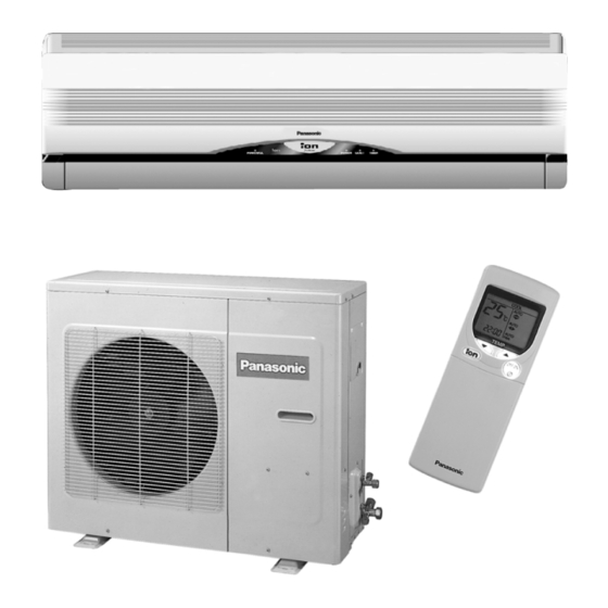
CS-V18CKE CU-V18CKE
CS-V24CKE CU-V24CKE
Page
2
3
6
10
12
13
14
15
15
16
20
22
22
© 2003 Matsushita Industrial Corp. Sdn. Bhd.
(11969-T). All rights reserved. Unauthorized copying
and distribution is a violation of law.
Order No. MAC0310023C2
Air Conditioner
Page
23
23
24
25
25
26
30
38
38
41
44
48
48
Advertisement
Table of Contents

Related Manuals for Panasonic CS-V18CKE


Summary of Contents for Panasonic CS-V18CKE
-
Page 1: Table Of Contents
Order No. MAC0310023C2 Air Conditioner CS-V18CKE CU-V18CKE CS-V24CKE CU-V24CKE CONTENTS Page Page 1 Features 8.6. Powerful Mode Operation 2 Functions 8.7. Random Auto Restart Control 3 Product Specifications 8.8. Airflow Direction Control 4 Dimensions 8.9. Delay ON Timer Control 5 Refrigeration Cycle Diagram 8.10. -
Page 2: Features
CS-V18CKE CU-V18CKE / CS-V24CKE CU-V24CKE 11.2. TOOLS FOR INSTALLING/SERVICING REFRIGERANT 15 Exploded View PIPING 16 Replacement Parts List 11.3. REFRIGERANT PIPING WORK 17 Exploded View 11.4. INSTALLATION, TRANSFERRING, SERVICING 18 Replacement Parts List 12 Servicing Information 19 Electronic Circuit Diagram 12.1. -
Page 3: Functions
CS-V18CKE CU-V18CKE / CS-V24CKE CU-V24CKE 2 Functions Remote Control Self illuminating button OFF / ON TEMP. Operation OFF / ON Room Temperature Setting Cooling, Soft Dry Operation. MODE • Temperature Setting (16°C to 30°C) Operation Mode Selection Automatic Operation •... - Page 4 CS-V18CKE CU-V18CKE / CS-V24CKE CU-V24CKE Indoor Unit AUTO OFF / ON Automatic Operation Button Random Auto Restart Control • Press for < 5s to operate Automatic • Operation is restarted randomly after operation mode. power failure at previous setting mode.
- Page 5 CS-V18CKE CU-V18CKE / CS-V24CKE CU-V24CKE Outdoor Unit Compressor Reverse Rotation Protection Control • To protect compressor from reverse rotation when there is an instantaneous power failure. Overload Protector • Inner protector. 60 Secs. Forced Operation Control • Once the compressor is activated, it does not stop within the first 60 secs.
-
Page 6: Product Specifications
CS-V18CKE CU-V18CKE / CS-V24CKE CU-V24CKE 3 Product Specifications Unit CS-V18CKE CU-V18CKE Power Source Phase, Voltage, Cycle Single, 230, 50 Hz Cooling Capacity kW (BTU/h) 5.30 (18,100) Moisture Removal l/h (Pint/h) 2.9 (6.1) Airflow Method OUTLET SIDE VIEW TOP VIEW INTAKE... - Page 7 CS-V18CKE CU-V18CKE / CS-V24CKE CU-V24CKE Unit CS-V18CKE CU-V18CKE Heat Exchanger Description Evaporator Condenser Tube material Copper Copper Fin material Aluminium (Pre Coat) Aluminium (Blue Coat) Fin Type Slit Fin Corrugated Fin Row / Stage (Plate fin configuration, forced draft) 2 × 15 2 ×...
- Page 8 CS-V18CKE CU-V18CKE / CS-V24CKE CU-V24CKE Unit CS-V24CKE CU-V24CKE Power Source Phase, Voltage, Cycle Single, 230, 50 Hz Cooling Capacity kW (BTU/h) 7.03 (24,000) Moisture Removal l/h (Pint/h) 4.0 (8.5) Airflow Method OUTLET SIDE VIEW TOP VIEW INTAKE Air Volume Indoor Air (Lo) /min (cfm) 13.9 (490)
- Page 9 CS-V18CKE CU-V18CKE / CS-V24CKE CU-V24CKE Unit CS-V24CKE CU-V24CKE Heat Exchanger Description Evaporator Condenser Tube material Copper Copper Fin material Aluminium (Pre Coat) Aluminium (Blue Coat) Fin Type Slit Fin Corrugated Fin Row / Stage (Plate fin configuration, forced draft) 2 × 15 2 ×...
-
Page 10: Dimensions
CS-V18CKE CU-V18CKE / CS-V24CKE CU-V24CKE 4 Dimensions... - Page 11 CS-V18CKE CU-V18CKE / CS-V24CKE CU-V24CKE...
-
Page 12: Refrigeration Cycle Diagram
CS-V18CKE CU-V18CKE / CS-V24CKE CU-V24CKE 5 Refrigeration Cycle Diagram... -
Page 13: Block Diagram
CS-V18CKE CU-V18CKE / CS-V24CKE CU-V24CKE 6 Block Diagram... -
Page 14: Wiring Diagram
CS-V18CKE CU-V18CKE / CS-V24CKE CU-V24CKE 7 Wiring Diagram... -
Page 15: Operation Details
CS-V18CKE CU-V18CKE / CS-V24CKE CU-V24CKE 8 Operation Details 8.1. Indoor Fan Speed Control • • • • Auto Fan Speed Control When set to Auto Fan Speed, the fan speed is adjusted between maximum and minimum setting as shown in the table. -
Page 16: Cooling Mode Operation
CS-V18CKE CU-V18CKE / CS-V24CKE CU-V24CKE 8.2. Cooling Mode Operation Cooling in operation according to Remote Control setting. Time Delay Safety Control (3 minutes) • • • • When the compressor is stopped by Remote Control, it restarts after 3 minutes when the Remote Control is turned ON. - Page 17 CS-V18CKE CU-V18CKE / CS-V24CKE CU-V24CKE 2. QLo fan speed (Transistor Motor) 3. QLo fan speed (Induction Motor) Automatic Fan Speed Mode When Automatic Fan Speed is selected at Remote Control during cooling operation. • • • • Fan speed rotates in the range of Hi to Me.
- Page 18 CS-V18CKE CU-V18CKE / CS-V24CKE CU-V24CKE Cooling Operation Time Diagram Quiet Operation Control (For Cooling Mode or cooling region of Soft Dry Mode) • • • • Purpose of this operation is to provide quite cooling operation compare to normal operation.
- Page 19 CS-V18CKE CU-V18CKE / CS-V24CKE CU-V24CKE • • • • Manual Fan Speed:- − − − − RPM control during Lo cool − − − − RPM control during Hi & Me cool • • • • Auto Fan Speed:- • • • • Quiet Mode Operation will stop if:- −...
-
Page 20: Soft Dry Mode Operation
CS-V18CKE CU-V18CKE / CS-V24CKE CU-V24CKE 8.3. Soft Dry Mode Operation • • • • The unit starts cooling operation until the room temperature reaches the setting temperature set on the Remote Control, and then Soft Dry operation will start. • • • • During Soft Dry operation, the Indoor Fan will operate at Lo- speed. - Page 21 CS-V18CKE CU-V18CKE / CS-V24CKE CU-V24CKE Soft Dry Operation Time Diagram Quiet Operation Control • • • • Same as Quiet Operation Control for Cooling Mode operation.
-
Page 22: Air Circulation Mode Operation
CS-V18CKE CU-V18CKE / CS-V24CKE CU-V24CKE 8.4. Air Circulation Mode Operation • • • • Fan operation only. Indoor fan speed selection by remote control and setting refer to Indoor Fan Speed Control. − − − − Manual Fan Speed Follow remote control setting −... -
Page 23: Powerful Mode Operation
CS-V18CKE CU-V18CKE / CS-V24CKE CU-V24CKE • • • • The mode judging temperature and standard setting temperature can be increased by 2°C, by open the circuit of JX1 at indoor electronic controller. 8.6. Powerful Mode Operation • • • • Purpose of this operation is to obtain the setting temperature quickly. -
Page 24: Airflow Direction Control
CS-V18CKE CU-V18CKE / CS-V24CKE CU-V24CKE 8.8. Airflow Direction Control Vertical Airflow Direction Auto-Control • • • • When set a Airflow Direction Auto-Control with remote control, the louver swings up and down as shown in the diagram. • • • • The louver does not swing when the Indoor Fan Motor stops during operation at the upper limit. -
Page 25: Delay On Timer Control
CS-V18CKE CU-V18CKE / CS-V24CKE CU-V24CKE Horizontal Airflow Direction manual Control • • • • When the manual Airflow Direction Selection Button is pressed, the automatic airflow is released and the airflow direction vane move left and right in the range shown in the diagram. -
Page 26: Ionizer Operation
CS-V18CKE CU-V18CKE / CS-V24CKE CU-V24CKE 8.11. Ionizer Operation Purpose To provide fresh air effect to user by discharging minus Ion to air. Control Condition a. Ionizer Only Operation. 1. When air-conditioner unit is at “OFF” condition (standby) and ION operation button at remote control is pressed. -
Page 27: Ionizer Operation Case Study
CS-V18CKE CU-V18CKE / CS-V24CKE CU-V24CKE 3. Ionizer operation status is not memorised by Micon. After OFF, when operation is “ON” again, air-conditioner operates without ionizer operation. However, during Cool mode etc + ionizer operation, if there is a power failure & then power resume, air conditioner shall on at that mode + ionizer operation. - Page 28 CS-V18CKE CU-V18CKE / CS-V24CKE CU-V24CKE Note: 1. 24 times checking: Actual Ion ON for 10s & OFF for 30 min continuously for 24 times. 2. 24 times count will be cleared when either one of the following conditions happen. a) 24 times count over, b) Ionizer cancel if press Ion button or power reset, c) Ion feedback signal is OK.
- Page 29 CS-V18CKE CU-V18CKE / CS-V24CKE CU-V24CKE...
-
Page 30: Operating Instructions
CS-V18CKE CU-V18CKE / CS-V24CKE CU-V24CKE 9 Operating Instructions... - Page 31 CS-V18CKE CU-V18CKE / CS-V24CKE CU-V24CKE...
- Page 32 CS-V18CKE CU-V18CKE / CS-V24CKE CU-V24CKE...
- Page 33 CS-V18CKE CU-V18CKE / CS-V24CKE CU-V24CKE...
- Page 34 CS-V18CKE CU-V18CKE / CS-V24CKE CU-V24CKE Plug / breaker...
- Page 35 CS-V18CKE CU-V18CKE / CS-V24CKE CU-V24CKE...
- Page 36 CS-V18CKE CU-V18CKE / CS-V24CKE CU-V24CKE...
- Page 37 CS-V18CKE CU-V18CKE / CS-V24CKE CU-V24CKE 33 / 34 33 / 34...
-
Page 38: Installation Instructions
CS-V18CKE CU-V18CKE / CS-V24CKE CU-V24CKE 10 Installation Instructions Required tools for Installation Works 1. Philips screw driver 5. Spanner 9. Gas leak detector 13. Multimeter 2. Level gauge 6. Pipe cutter 10. Measuring tape 14. Torque wrench 18 N.m (1.8 kgf.m) 55 N.m (5.5 kgf.m) - Page 39 CS-V18CKE CU-V18CKE / CS-V24CKE CU-V24CKE 1. This equipment must be earthed. It may cause electrical shock if grounding is not perfect. 2. Do not install the unit at place where leakage of flammable gas may occur. In case gas leaks and accumulates at surrounding of the unit, it may cause fire.
- Page 40 CS-V18CKE CU-V18CKE / CS-V24CKE CU-V24CKE Attached accessories Example: For W24CK If the unit is installed at a 10m distance, the quantity of additional refrigerant should be 75g...(10 - 7.5)m × 30g/m = Indoor/Outdoor Unit Installation Diagram Applicable piping kit CZ-4F5, 7, 10AN (V18CK, W18CK)
-
Page 41: Indoor Unit
CS-V18CKE CU-V18CKE / CS-V24CKE CU-V24CKE 10.2. INDOOR UNIT 10.2.1. SELECT THE BEST LOCATION 10.2.3. TO DRILL A HOLE IN THE WALL (Refer to “Select the best location” AND INSTALL A SLEEVE OF section) PIPING 1. Insert the piping sleeve to the hole. - Page 42 CS-V18CKE CU-V18CKE / CS-V24CKE CU-V24CKE 3. For the embedded piping (This can be used for left rear piping & left bottom piping also.)
- Page 43 CS-V18CKE CU-V18CKE / CS-V24CKE CU-V24CKE 10.2.5. CONNECT THE CABLE TO THE INDOOR UNIT 1. The inside and outside connecting cable can be connected without removing the front grille. 2. Connecting cable between indoor unit and outdoor unit shall be approved polychloroprene sheathed 3 × 2.5 mm (V18CK, V24CK) or 5 ×...
-
Page 44: Outdoor Unit
CS-V18CKE CU-V18CKE / CS-V24CKE CU-V24CKE 10.3. OUTDOOR UNIT HOW TO TAKE OUT FRONT GRILLE Please follow the steps below to take out front grille if 10.3.1. SELECT THE BEST LOCATION necessary such as when servicing. (Refer to “Select the best location”... -
Page 45: Evacuation Of The Equipment
CS-V18CKE CU-V18CKE / CS-V24CKE CU-V24CKE CUTTING AND FLARING THE PIPING 1. Please cut using pipe cutter and then remove the burrs. 2. Remove the burrs by using reamer. If burrs is not removed, gas leakage may be caused. Turn the piping end down to avoid the metal powder entering the pipe. -
Page 46: Connect The Cable To The Outdoor Unit
CS-V18CKE CU-V18CKE / CS-V24CKE CU-V24CKE 10.3.5. CONNECT THE CABLE TO THE OUTDOOR UNIT 1. Remove the control board cover from the unit by loosening the screw. 2. Connecting cable between indoor unit and outdoor unit shall be approved polychloroprene sheathed 3 × 2.5 mm (V18CK, V24CK) or 5 ×... -
Page 47: Pipe Insulation
CS-V18CKE CU-V18CKE / CS-V24CKE CU-V24CKE 10.3.6. PIPE INSULATION EVALUATION OF THE PERFORMANCE • • • • Operate the unit at cooling operation mode for fifteen 1. Please carry out insulation at pipe connection portion as mentioned in Indoor/Outdoor Unit Installation Diagram. -
Page 48: Installation And Servicing Air Conditioner Using R410A
CS-V18CKE CU-V18CKE / CS-V24CKE CU-V24CKE 11 Installation and Servicing Air Conditioner Using R410A 11.1. OUTLINE 11.1.1. About R410A Refrigerant 1. Converting air conditioners to R410A Since it was declared in1974 that chlorofluorocarbons (CFC), hydro chlorofluorocarbons (HCFC) and other substances pose a destructive danger to the ozone layer in the earth’s upper stratosphere (20 to 40 km above the earth), measures have been... -
Page 49: Tools For Installing/Servicing Refrigerant
CS-V18CKE CU-V18CKE / CS-V24CKE CU-V24CKE d. R410A refrigerating machine oil Conventionally, mineral oil or a synthetic oil such as alkylbenzene has been used for R22 refrigerating machine oil. Because of the poor compatibility between R410A and conventional oils like mineral oil, however, there is a tendency for the refrigerating machine oil to collect in the refrigerating cycle. -
Page 50: R410A Tools
CS-V18CKE CU-V18CKE / CS-V24CKE CU-V24CKE 11.2.2. R410A Tools 1. Copper tube gauge for clearance adjustment (used when flaring with the conventional flaring tool (clutch type)) • • • • This gauge makes it easy to set the clearance for the copper tube to 1.0-1.5 mm from the clamp bar of the... - Page 51 CS-V18CKE CU-V18CKE / CS-V24CKE CU-V24CKE 5. Charging hose • • • • The pressure resistance of the charging hose has been raised to match the higher pressure of R410A. The hose material has also been changed to suit HFC use, and the size of the fitting has been changed to match the manifold ports.
- Page 52 CS-V18CKE CU-V18CKE / CS-V24CKE CU-V24CKE 8. Electronic scale for refrigerant charging • • • • Because of the high pressure and fast vaporizing speed of R410A, the refrigerant cannot be held in a liquid phase inside the charging cylinder when charging is...
-
Page 53: Refrigerant Piping Work
CS-V18CKE CU-V18CKE / CS-V24CKE CU-V24CKE 11.3. REFRIGERANT PIPING WORK 11.3.1. Piping Materials It is recommended that you use copper and copper alloy jointless pipes with a maximum oil adherence of 40 mg/10m. Do not use pipes that are crushed, deformed, or discolored (especially the inside surface). If these inferior pipes are used, impurities may clog the expansion valves or capillaries. - Page 54 CS-V18CKE CU-V18CKE / CS-V24CKE CU-V24CKE Table 11 R410A flaring dimensions Nominal Outside Wall thickness A (mm) diameter diameter (mm) R410A flaring Conventional flaring tool (mm) tool, clutch type Clutch type Wing-nut type 6.35 0 - 0.5 1.0 - 1.5 1.5 - 2.0 9.52...
-
Page 55: Installation, Transferring, Servicing
CS-V18CKE CU-V18CKE / CS-V24CKE CU-V24CKE b. Copper pipes Use only copper pipes with the thickness given in table 10, and with minimal impurities. Because the surface of the pipe is exposed, you should take special care, and also take measures such as marking the pipes to make sure they are easily distinguished from other piping materials, to prevent mistaken use. -
Page 56: Transferring (Using New Refrigerant Piping)
CS-V18CKE CU-V18CKE / CS-V24CKE CU-V24CKE 11.4.2. Transferring (Using New Refrigerant Piping) 1. Removing the unit a. Collecting the refrigerant into the outdoor unit by pumping down The refrigerant can be collected into the outdoor unit (pumping down) by pressing the TEST RUN button, even when the temperature of the room is low. - Page 57 CS-V18CKE CU-V18CKE / CS-V24CKE CU-V24CKE 3. Fully open the handle Lo of the manifold gauge, turn on the power of the vacuum pump and continue the vacuum process for at least one hour. 4. Confirm that the low pressure gauge shows a reading of -0.1 Mpa (-76 cmHg), then fully close the handle Lo, and turn off the vacuum pump.
- Page 58 CS-V18CKE CU-V18CKE / CS-V24CKE CU-V24CKE 11.4.6. Brazing As brazing requires sophisticated techniques and experiences, it must be performed by a qualified person. In order to prevent the oxide film from occurring in the pipe interior during brazing, it is effective to proceed with brazing while letting dry nitrogen gas (N ) flow.
-
Page 59: Servicing Information
CS-V18CKE CU-V18CKE / CS-V24CKE CU-V24CKE 12 Servicing Information Caution: • • • • Pb free solder has a higher melting point than standard solder; Typically the melting point is 50 - 70°F (30 - 40°C) higher. Please use a high temperature soldering iron. In case of the soldering iron with temperature control, please set it to 700 ± 20°F (370 ± 10°C). -
Page 60: Cross Flow Fan And Indoor Fan Motor Removal Procedures
CS-V18CKE CU-V18CKE / CS-V24CKE CU-V24CKE 12.2. Cross Flow Fan and Indoor Fan Motor Removal Procedures 1. In order to remove the Cross Flow Fan and Indoor Fan Motor, Control Board need to be taken out by releasing all the connectors as indicated below. - Page 61 CS-V18CKE CU-V18CKE / CS-V24CKE CU-V24CKE 6. Remove the Bearing. (Fig. 9) 7. Remove the screws at the left of the Evaporator. (Fig. 9) Fig. 9 8. Push up the Evaporator and pull out the Cross Flow Fan from shaft. By then, Fan Motor can be taken out. (Fig. 10).
- Page 62 CS-V18CKE CU-V18CKE / CS-V24CKE CU-V24CKE • • • • Remote Control Reset When the batteries are inserted for the first time, or the batteries are replaced, all the indications will blink and the remote control might not work. If this happen, remove the cover of the remote control and you will find a resetting terminal, and by shorting it with a minus screwdriver, it will return to normal.
-
Page 63: Troubleshooting Guide
CS-V18CKE CU-V18CKE / CS-V24CKE CU-V24CKE 13 Troubleshooting Guide 13.1. Refrigeration cycle system In order to diagnose malfunctions, make sure that there are no electrical problems before inspecting the refrigeration cycle. Such problems include insufficient insulation, problem with the power source, malfunction of a compressor and a fan. -
Page 64: Diagnosis Methods Of A Malfunction Of A Compressor
CS-V18CKE CU-V18CKE / CS-V24CKE CU-V24CKE 13.1.1. Relationship between the condition of the air conditioner and pressure and electric current Cooling Mode Condition of the air conditoner Low Pressure High Pressure Electric current during operation Insufficient refrigerant (gas leakage) Clogged capillary tube or... -
Page 65: Technical Data
CS-V18CKE CU-V18CKE / CS-V24CKE CU-V24CKE 14 Technical Data... - Page 66 CS-V18CKE CU-V18CKE / CS-V24CKE CU-V24CKE 230V Outdoor Temp. (°C) Indoor wet bulb temp. 17.0°C 5.26 3.99 1.49 4.91 3.82 1.61 4.57 3.67 1.72 4.16 3.49 1.85 19.0°C 5.30 1.63 19.5°C 5.77 4.17 1.52 5.40 4.01 1.64 5.02 3.86 1.75 4.56 3.67...
-
Page 67: Exploded View
CS-V18CKE CU-V18CKE / CS-V24CKE CU-V24CKE 15 Exploded View Note: The above exploded view is for the purpose of parts disassembly and replacement. The non-numbered parts are not kept as standard service parts. -
Page 68: Replacement Parts List
CS-V18CKE CU-V18CKE / CS-V24CKE CU-V24CKE 16 Replacement Parts List <Model: CS-V18CKE CS-V24CKE> REF. NO. PART NAME & DESCRIPTION QTY. CS-V18CKE CS-V24CKE REMARKS ← ← ← ← CHASSY COMPLETE CWD50C1293 ← ← ← ← FAN MOTOR CWA981056 ← ← ← ←... -
Page 69: Exploded View
CS-V18CKE CU-V18CKE / CS-V24CKE CU-V24CKE 17 Exploded View Note: The above exploded view is for the purpose of parts disassembly and replacement. The non-numbered parts are not kept as standard service parts. -
Page 70: Replacement Parts List
CS-V18CKE CU-V18CKE / CS-V24CKE CU-V24CKE 18 Replacement Parts List <Model: CU-V18CKE CU-V24CKE> REF. NO. PART NAME & DESCRIPTION QTY. CU-V18CKE CU-V24CKE REMARKS CHASSY ASS’Y CWD50K515B CWD50K514B ← ← ← ← SOUND PROOF BOARD CWH15223 FAN MOTOR BRACKET CWD54238 CWD54237 ← ← ← ←... -
Page 71: Electronic Circuit Diagram
CS-V18CKE CU-V18CKE / CS-V24CKE CU-V24CKE 19 Electronic Circuit Diagram CS-V18CKE CU-V18CKE CS-V24CKE CU-V24CKE SCHEMATIC DIAGRAM 1/3 ELECTRONIC CONTROL UNIT TEMPERATURE FUSE TEST R54 1k Q001 R12 1k R35 5.1k BZ01 0.01 TO OUTDOOR YELLOW AC01 (WHT) CAPACITOR RY-PWR BLUE (XH4) 0.01... - Page 72 CS-V18CKE CU-V18CKE / CS-V24CKE CU-V24CKE SCHEMATIC DIAGRAM 2/3 CN-MAIN R11 1k 0.01µ 47µ 0.1µ 0.01µ 0.01µ R10 10k 100µ 0.01µ R03 100Ω R02 20k 0.1µ 510Ω R29 1k 1000p (MB) P50/A8 RY-PWR DRIVE SIGNAL STEPPING P51/A9 MOTOR AUTO OPERATION R13 220...
- Page 73 CS-V18CKE CU-V18CKE / CS-V24CKE CU-V24CKE SCHEMATIC DIAGRAM 3/3 ELECTRONIC CONTROL UNIT R020 F001 D101 R026 R016 CN001 R052 R027 L001 C003 R105 R031 Z001 C005 C002 R017 R051 DB004 C004 C007 C012 L101 R050 ZD002 Q004 C103 R015 R013 R048...
- Page 74 CS-V18CKE CU-V18CKE / CS-V24CKE CU-V24CKE How to use electronic circuit diagram TIMER TABLE Test Mode Name Time (When test point Remarks Short-circuited) Real Timer 1 hr. 1 min. 10 min. 10 sec. 1 min. 1 sec. Time Delay Safety Control 2 min.
-
Page 75: Remote Control
CS-V18CKE CU-V18CKE / CS-V24CKE CU-V24CKE 19.1. REMOTE CONTROL... -
Page 76: Print Patternindoor Unit Printed Circuit
CS-V18CKE CU-V18CKE / CS-V24CKE CU-V24CKE 19.2. PRINT PATTERN INDOOR UNIT PRINTED CIRCUIT BOARD... -
Page 77: Print Patternindoor Unit Printed Circuit
CS-V18CKE CU-V18CKE / CS-V24CKE CU-V24CKE 19.3. PRINT PATTERN INDOOR UNIT PRINTED CIRCUIT BOARD [MAICO] Printed in Malaysia...
Need help?
Do you have a question about the CS-V18CKE and is the answer not in the manual?
Questions and answers