Table of Contents
Advertisement
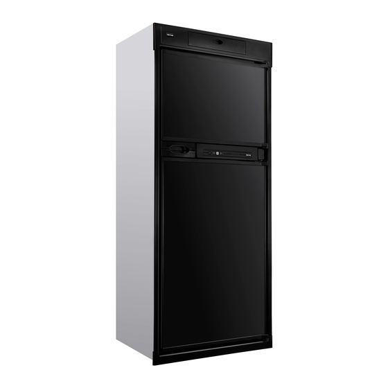
N614E.3F (184 L (approx) 3-way operation with LP gas, 240 volts AC, or 12 volts DC )
!
WARNING
FOR YOUR SAFETY
Do not store or use gasoline or other flammable vapors and liquid in the
vicinity of this or any other appliance.
FOR YOUR SAFETY
If you smell gas:
DO NOT install this refrigerator in below deck marine applications. Do not install this refrigerator in
!
WARNING
fixed indoor cabin or other dwelling applications. This refrigerator must use only Thetford designed and
approved outside air intake and exhaust ventilation for correct and safe operation. Any other ventilation
could cause lethal combustion exhaust fumes and/or explosive LP gas fumes to be in the living area and/or
to be below deck.
Thetford Australia
41 Lara Way
Campbellfield, VIC 3061
Installation Manual
For Australian refrigerator model:
Improper installation, adjustment, alteration, service or maintenance
can cause personal injury or property damage. Refer to this manual.
For assistance or additional information, contact a qualified installer,
service agency, or the LP gas supplier.
1. Open windows.
2. Don't touch electrical switches.
3. Extinguish any open flame.
4. Immediately call your gas supplier.
Thetford Customer Support
Telephone: (61) 03-9358-0700
Fax: (61) 03-9357-7060
Web Site: www.thetford.com.au
Part No. 636771B (4/02/2015)
Advertisement
Table of Contents

Related Manuals for Thetford N614E.3F


Summary of Contents for Thetford N614E.3F
-
Page 1: Installation Manual
Installation Manual For Australian refrigerator model: N614E.3F (184 L (approx) 3-way operation with LP gas, 240 volts AC, or 12 volts DC ) Improper installation, adjustment, alteration, service or maintenance WARNING can cause personal injury or property damage. Refer to this manual. -
Page 2: Table Of Contents
Table of Contents Safety Awareness ....................................2 Safety Instructions ....................................2 Certification and Code Requirements..............................3 Ventilation Requirements..................................3 Key Refrigerator Dimensions................................4 Assemble the Enclosure ..................................5 Install the Upper and Lower Vents................................5 Install Decorative Door Panels ................................9 Install the Refrigerator ..................................9 Reverse the door swing ..................................10 Connect the Electrical Components ..............................13 Connect the 240 volt AC supply ..............................13 Connect the 12 volt DC supply ..............................13... -
Page 3: Certification And Code Requirements
The refrigerator is made for installation in a caravan or a recreational vehicle. The installation must obey the requirements of this “installation Manual” for the THETFORD limited warranty to be in effect. The installation must agree with local codes. In the absence of local codes, the installation must obey these standards: - Gas Installations AS5601. -
Page 4: Key Refrigerator Dimensions
Certified installation needs one lower intake vent and one upper exhaust vent. Install the upper exhaust vent either through the roof or through the side wall of the vehicle exactly as written in this manual. Any other installation method voids both the certification and the factory warranty of the refrigerator. -
Page 5: Assemble The Enclosure
Assemble the Enclosure 1. Make sure the enclosure is: 1415mm high x 600mm wide x 610mm deep. 2. Make sure the floor is solid and level. - The floor must be metal or a wood panel and extend the full width and depth of the enclosure. - The floor must be able to support the weight of the refrigerator and its contents. - Page 6 3. Install the upper exhaust vent: Make sure that no sawdust, insulation, or other WARNING construction debris is on the refrigerator or in the enclosure. Debris can cause a combustion hazard and prevent the refrigerator from operating correctly. Tighten the screws of the upper roof exhaust cap to 11.5kgf/cm. NOTICE Also make sure that the air flow around the upper roof exhaust cap is not blocked or decreased by other roof mounted features such as a...
- Page 7 - If the depth of the enclosure is more than 660mm, install a wood or an aluminum or galvanized sheet solid box baffle [21] in the rear of the enclosure (See Art02267 and Art02268). - Make sure that the bottom of the solid box baffle is 455mm to 470mm above the bottom of the enclosure [17] (205mm to 220mm above the top of the lower intake vent opening REF) [18] .
-
Page 8: Make Sure There Is Less Than 6Mm Clearance [15] Between The Baffle
- Install the upper side-wall exhaust vent [24] (See Art02262 and Art02263). - Make sure the distance [25] from the bottom of the enclosure to the top of the rough opening for the upper exhaust vent is at least 1400mm. - Align the upper exhaust vent [24] horizontally above the lower intake vent [9] of the refrigerator. -
Page 9: Install Decorative Door Panels
- Make sure that the vertical top edge of the baffle is between 6mm [213] below the condenser and 38mm above the bottom of the condenser. - Make sure that there is 6mm or less clearance [15] between the rear of the condenser and the baffle. Install Decorative Door Panels The doors are made to accept decorative panels. -
Page 10: Reverse The Door Swing
- Install the upper trim piece [40] over the control panel: - Align the four (4) metal mounting clips on the back of the upper trim piece with the four (4) rectangular slots in the mounting bracket of the refrigerator. - Push the upper trim piece firmly until all four (4) mounting clips engage the rectangular slots with a “snap”... - Page 11 - Remove the three plastic hole caps that are near the strike plate. - Remove the L-shaped plastic covers that are opposite the hinges. - Remove and save the screws from the upper cabinet hinge [66a] of each door. - Put each of these hinges on the other side of the refrigerator as the lower hinge [66b].
- Page 12 3. Change the position of the door handles (See Art01727): - Remove the screws [41] and door handle [70] from each door. - Reverse each door handle and put the lower door handle on the upper door and the upper door handle on the lower door. - Attach each door handle with the screws.
-
Page 13: Connect The Electrical Components
Connect the Electrical Components The current draws are nominal values. AC Operation 240 VAC (216 VAC min. - 264 VAC max.) Current Draw: AC heater 1.25 A at 240 VAC DC Operation 12 VDC (11.5 VDC min. - 15.4 VDC max.) Current Draw: DC Heater 17.14 A at 12 VDC... -
Page 14: Connect The Lp Gas Components
2. Install a fuse in DC power supply wires between the battery and the refrigerator: - Put fuse as close to the battery as possible. 3. Connect the DC power supply wires: These models have 2 connection points to prevent the battery from being discharged by the refrigerator when the engine is not running. -
Page 15: Operation Check
- That the door gasket seals correctly. - That the refrigerator and freezer are defrosted. If you unable to correct your refrigerator problem after using this guide, see your dealer or an authorized Thetford Service Center. Installation / Owner’s Manual 15... - Page 16 Installation / Owner’s Manual 16...
Need help?
Do you have a question about the N614E.3F and is the answer not in the manual?
Questions and answers