
Subscribe to Our Youtube Channel
Related Manuals for SportsArt Fitness S775


Summary of Contents for SportsArt Fitness S775
- Page 1 S775 15” TFT LCD Pinnacle Cross Trainer Owner’s Manual Sports Art Industrial Co., Ltd. ISO 9001/14001 Certified 2014.11 No. 11, Gong Huan Rd. Tainan City, Taiwan R.O.C. www.gosportsart.com...
-
Page 2: Table Of Contents
STEP 12 TV Terminal and Netwotk ............34 STEP 13 Install the TV Cable ............... 35 STEP 14 Unit Inspection ..............5. UNDERSTAND THE S775-15 DISPLAY ........DISPLAY Overview ................37 DISPLAY Home Page Display Sequence ..........37 DISPLAY Keys ..................38 DISPLAY Windows ................ -
Page 3: Introduction
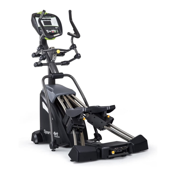
1. INTRODUCTION Congratulations on your purchase of one of the finest exercise products on the market today, the SportsArt S775 15” Touch Screen Pinnacle Cross Trainer. Constructed of high quality materials and designed for years of reliable usage, this product was made to become an integral part of your commercial fitness venue. -
Page 4: Safety Precautions
2. SAfETy PRECAUTIONS Your SportsArt pinnacle cross trainer was designed and built for optimum safety. However certain precautions apply whenever you use your pinnacle cross trainer. Please read the entire manual before assembly and operation. Also, please note the following safety precautions: ●... - Page 5 2. SAfETy PRECAUTIONS (CONTINUED) ● Children should be supervised to ensure that they do not play with the pinnacle cross trainer. Caution If you feel any pain or abnormal sensation, STOP YOUR WORKOUT and consult your physician immediately. Work within your recommended exer- cise level.
- Page 6 2. CONSIGNES DE SÉCURITÉ IMPORTANTES • Votre pinnacle croix trainer SportsArt a été conçu et fabriqué afin d’assurer une sécurité optimale. Cependant certaines précautions s’appliquent chaque fois que vous utilisez votre pinnacle croix trainer de course. • Lisez entièrement le manuel avant l’assemblage et l’utilisation. Veuillez aussi noter les consignes de sécurité...
- Page 7 2. CONSIGNES DE SÉCURITÉ (SUITE) • Pour diminuer le risque de choc électrique, débranchez toujours ce l’ pinnacle croix trainer de course de la prise de courant, immédiatement après utilisation et avant le nettoyage. Ce pinnacle croix trainer n’est pas destiné à être utilisé par des personnes (y compris des enfants) dont les capacités physiques, sensorielles ou mentales sont réduites ou qui ne disposent pas de l’expérience ou du savoir nécessaires, sauf si celles-ci ont au préalable été...
-
Page 8: List Of Parts
3. LIST Of PARTS Assembly Parts Name Qty. Name Qty. Right support lower Display neck assembly cover Pedestal assembly A12 Feeder cord Main frame A13 Right handle cover Right glide track A14 Left handle cover Left glide track A15 Connecting board Rear adjustment base A16 Right pedal Right support... - Page 9 Components in the Hardware Kit Name Qty. Specification Notes 30 Cover cap 31 Mushroom top Phillips screw M4*L16 32 Phillips screw M5*L15 33 Ground wire Screw socket L shaped Allen wrench (M4) L shaped Allen wrench (M6) Double open end wrench (13*17) Double open end wrench (17*23)
- Page 10 Components on the Product Name Specification Notes Axle C M10*L78 Bushing B ØD20*d12.2*L14.5 Nylon hex lock nut Fan cover Mushroom top Phillip screw M4*L16 Bevelled head inner hex screw M6*L15 Pedestal cover Mushroom top Phillip screw M4*L16 Inner hex screw M8*P1.25*L25 Serrated washer D18*d8.5*t2.0*19T...
-
Page 11: Assemble The Product
4. ASSEMBLE THE PRODUCT Follow instructions below to assemble this product. Note that in this manual the words “left” and “right” are used to refer to the product and its parts. As such, these designations correspond to the “left” and “right” sides of a person in position to exercise on this product. -
Page 12: Step 1 Install The Rear Adjustment Base
STEP 1 Install the Rear Adjustment Base Please follow instructions (a) through (d) to install the rear adjustment base. (a) First, remove the rear footplate (53) and screws (52) from the rear adjustment base (A6) (b) Remove the mount (58) and screws (57) from the rear adjustment base (A6) Note: The removed parts are bilateral. - Page 13 STEP 1 Install the Rear Adjustment Base (Continued) (c) Remove screws (56) from the main frame (A3). (b) Secure the rear adjustment base (A6) to the main frame (A3) with screws (56). Secure screws at area A first. and then secure screws at area B. (Note: Make sure the serrated side of washer touches the frame.)
-
Page 14: Step 2 Install The Left And Right Glide Track
STEP 2 Install the Left and Right Glide Track Please follow instructions (a) through (j) to install the left and right glide track. (a) First, remove screws (79) from the right glide track (A4). (b) There are rubber pads on the foot pedals (A16). Fold the rubber pad up to access screws. - Page 15 STEP 2 Install the Left and Right Glide Track (Continued) (c) First, remove the covers (59) (60) (62) from the main frame (A3). (d) Remove the axle (63A) and the nut (63) from the main frame (A3). (Note: The axle may drop off.)
- Page 16 STEP 2 Install the Left and Right Glide Track (Continued) Install the right glide track (A4) and the main frame (A3) (e) First, loosen 3 piece screws from area (d1) covers (Do not reomove these screws) and then place the right glide track (A4) on the main frame (A3) and insert the axle (63) into the main frame (A3) and the right glide track (A4), and loosely secure it with nut.
- Page 17 STEP 2 Install the Left and Right Glide Track (Continued) (f) Follow the same procedure to install the left glide track (A5).
- Page 18 STEP 2 Install the Left and Right Glide Track (Continued) Install the right and left glide track (A4) (A5) and the rear adjustment base (A6). (g) Remove the axle (77) from the right and left glide track (A4) (A5) and insert the ball socket.
-
Page 19: Step 3 Install The Belts
STEP 3 Install the Belts Do not cross the belts, make sure the belts are parallel as shown. (Note: The belt are side-specific.) Please follow instructions (a) through (d) to install the belts. (a) First, remove the axle (64) from the left glide track (A5). (b) Insert two belts and bushing from the main frame through the axle. - Page 20 STEP 3 Install the Belts (Continued) After installing the belts, please inspect the position of the belt on the idler pulley. The belt should be in the middle of the idler pulley. Make sure that the belt is not outside of the idler pulley. If the belt is in the wrong position, lift the pedal to loosen the belt and then place the belt in the middle of the idler pulley.
-
Page 21: Step 4 Install The Display Neck And Pedestal Assembly
STEP 4 Install the Display Neck and Pedestal Assembly Please follow instructions (a) through (l) to install the display neck and pedestal assembly. (a) First, remove the fan cover (65) and screws (66) from the display neck assembly (A1). (b) Remove the pedestal mount (76), pedestal cover (68) and screws (67) (69) from the pedestal assembly (A2). - Page 22 STEP 4 Install the Display Neck and Pedestal Assy (Cont.) (c) Thread five date cables of the pedestal assembly (A2) out the hole C1 in the fan cover (54) and then insert the fan cover (65) onto place on the pedestal assembly (A2) as shown.
- Page 23 STEP 4 Install the Display Neck and Pedestal Assy (Cont.) (e) Disconnect the zip tie to release five date cables from the pedestal assembly (A2). (f) Pull five date cables from the pedestal assembly (A2) to thread through the hole G as shown and connect thenm to the five date cables from the display neck assembly (A1), and then push the black cover of two date cables to cover the end of two date cables as shown.
- Page 24 STEP 4 Install the Display Neck and Pedestal Assy (Cont.) (i) Pull the feeder cord downward to thread through the pedestal and out the hole H as shown and then disconnect the feeder cord from the cables. (j) Connect two cables (M2) and two cables (M1) from the pedestal as shown and then tuck the cables (M2) (M1) back into the hole H of pedestal for safely.
- Page 25 STEP 4 Install the Display Neck and Pedestal Assy (Cont.) (k) Place the display neck assembly (A1) into the place of the pedestal mount (76) and secure them with screws (32) as shown. (Note: Avoid pinching or crimping the cables during the assembly.) (l) Secure the fan cover (65) to the display neck assembly with screws (66) as shown.
-
Page 26: Step 5 Install The Pedestal Assembly And The Main Frame
STEP 5 Install the Pedestal Assembly and the Main frame Note: Make sure the water guard of the pedestal has been placed on the pedestal as shown. Please follow instructions (a) through (c) to install the pedestal assembly and the main frame. (a) First, remove screws (70) from the main frame (A3). -
Page 27: Step 6 Install The Left And Right Support
STEP 6 Install the Left and Right Support Please follow instructions (a) through (d) to install the left and right support. (a) First, remove screws (73) from the main frame (A3). (b) Secure the right and left support (A7) (A8) to the main frame with the connecting board (A15). -
Page 28: Step 7 Install The Covers
STEP 7 Install the Covers Please follow instructions (a) through (i) to install the covers. (a) Secure the top cover (62) back into place with screws (61). (b) Click the front cover (60) back into place and insert the cover cap (59). (c) Press the water guard downward into place against the top cover. - Page 29 STEP 7 Install the Covers (Continued) Collect the cables and tuck them into the pedestal assembly as shown before installing the pedestal cover (68). (f) Secure the pedestal cover (68) with screws (69), wihtout pinching or crimping the cables.
- Page 30 STEP 7 Install the Covers (Continued) (g) Secure the left carriage rear cover (54) with screws (52). (h) Secure the right carriage rear cover (51) with screws (52). (i) Secure the rear footplate (53) with screws (52) and then insert the cap (55) into place as shown.
-
Page 31: Step 8 Moving The Unit
STEP 8 Moving the Unit Note: Two people will be required for moving the unit. Stand on the left and right sides, behind the rear base. Grip the glide track in area A with both hands as shown. Simultaneously lift the unit and roll it into place carefully. -
Page 32: Step 9 Leveling The Unit
STEP 9 Leveling the Unit (a) To function properly, the unit must be level on the floor. (b) Loosen the leveler nut. (c) Rotate the leveler feet at area C and check if the unit is level. (d) Rotate the leveler feet at area B downward until it touches the floor. (e) Rotate the leveler nut at areas B and C upward, against the frame of the unit, to secure this position. -
Page 33: Step 10 Install The Left And Right Support Lower Cover
STEP 10 Install the Left and Right Support Lower Cover Please follow instructions (a) through (b) to install the left and right support lower cover. (a) Remove screws (75) from the right support (A7). (b) Secure the right support lower cover (A11) to the unit with screws (75). Note: Follow the same procedure to secure the left support lower cover (A10). -
Page 34: Step 11 Install The Power Cord
STEP 11 Install the Power Cord (a) First remove screws (80) from the power cord socket on the product. (b) Insert the power cord into place on the product. (c) Secure power cord connector screws (80) and then insert the other end of the power cord (A19) into the appropriate power supply socket in the wall. -
Page 35: Step 12 Tv Terminal And Netwotk
STEP 12 TV Terminal and Netwotk (a) NETWORK: Connect to Ethernet. (b) CATV: Connect to NTSC or PAL (c) AV Terminal: Connect to DVD Player or Media Player. (d) DTV: Connect to Digital TV. -
Page 36: Step 13 Install The Tv Cable
STEP 13 Install the TV Cable NTSC system: Directly connect your local area connector as shown. PAL system: Insert NTSC To PAL Adapter (A18) as shown and conect to your local area connector. -
Page 37: Step 14 Unit Inspection
STEP 14 Unit Inspection Please follow instructions (a) through (c) to inspect operation and confirm that the unit is working properly after all parts are assembled. Note: Inspect the unit is stable without moving. (a) Pull the knob at area K to make sure that every hole can be engaged easily and the handle can be adjusted upward and downward. -
Page 38: Understand The S775-15 Display
5. UNDERSTAND THE S775-15 DISPLAy DISPLAy Overview The S775-15 display was designed to help people obtain their fitness goals simply and conveniently. Please familiarize yourself with the features of this display and thereby get optimum benefit and enjoyment from this product. -
Page 39: Display Keys
DISPLAy Keys 1. Energy Smart wake up button 2. Headphone Jacks DISPLAy Windows 1. SPEED: 0.1 mph (kph) 2. LEVEL: 1 - 40 3. TIME: 0:00 to 600:00 4. DISTANCE: 0.00 to 9999 kilometers or miles 5. CALORIES: Range 0 to 9999 kcal 6. -
Page 40: Home Page
4. USER PROFILE key: to set up user’s profile 5. DEFAULT SETTINGS key: to enter engineering settings 6. HELP key: to find out information and/or instruction for each function 7. GO GREEN key: to learn more about SportsArt Fitness’ Green Mission... -
Page 41: Operate The Product
6. OPERATE THE S775-15 ELLIPTICAL There are two ways to start operating this product: (1) Press the QUICK START key, or (2) press the PROGRAM SELECTION key to enter a preset program. Using the QUICK START key allows you to begin exercising immediately, without first entering user information. - Page 42 OPERATION Quick Start (Continued) 7. Program selection button: switch current program to a different program during exercising. 8. Left-handed or right-handed buttons: press either hand to put the Quick keys (10) on the left side of the screen or right side. 9.
-
Page 43: Operation Program Selection
OPERATION Quick Start (Continued) Workout summary: OPERATION Program Selection The program mode provides user-specific caloric expenditure and target heart rate values, along with accumulated time, total distance, and total caloric expenditure values for individual users. WORKOUT PROGRAMS: Preset workout programs include: Manual, Plateau, Interval (1:1, 1:2, 2:2) programs, Vari-stride &... - Page 44 OPERATION Program Selection (Continued) Display during exercise is as shown below. The human icon indicates the current progress; the finished portion is showing in Grey; current position is flashing orange and white and the future portion is showing in white. The progress bar is showing below to indicate user progress.
- Page 45 OPERATION Program Selection (Continued) Display during exercise is as shown below. The human icon indicates the current progress; the finished portion is showing in Grey; current position is flashing orange and white and the future portion is showing in white. The progress bar is showing below to indicate user progress.
- Page 46 OPERATION Program Selection (Continued) INTERVAL (1:1, 1:2, 2:2) There are two segments, a rest segment and a work segment, each of which can have a different time and resistance setting. There are three interval programs: 1:1, 1:2, and 2:2. Numbers in these programs represent time. For instance, in the 1:2- interval workout, one indicates a segment of one-minute in duration, followed by a second segment of two minutes in duration.
- Page 47 OPERATION Program Selection (Continued) Display during exercise is the same as Plateau program, refer to pervious program pages for details. fAT BURN In this program, there are 1-20 different difficulty stages to select from. Once Manual-Level program is selected, it will enter user profile setting page. (1) Age: enter user’s age.
- Page 48 OPERATION Program Selection (Continued) RANDOM Each time the RANDOM key is pressed a different randomly generated workout illustration will appear. There is an almost infinite number of randomly generated workouts. Once Random program is selected, it will enter user profile setting page: Age, weight, goal and speed. After setting, press START to begin the program.
- Page 49 OPERATION Program Selection (Continued) Display during exercise is as shown below. The number above the Heart icon represents the current heart rate. The progress bar is showing below to indicate user progress. The graph in the middle represents the target RPM vs.
- Page 50 OPERATION Program Selection (Continued) fIT TEST The FIT TEST program is designed for physical fitness assessments. Once the Fit Test program is selected, it will enter user profile setting page: Age, weight, height, gender. Target heart rate and BMI boxes are calculated and filled based on the information user entered;...
-
Page 51: Operation Media Selection
OPERATION Media Selection There are several media input options built in this console; such as TV(TV, DTV, A/V), USB(Music/Video) as well as 5 web quick keys. There is a built in remote control for changing the channels and volume control. Channel changing is compatible with TV & DTV only. Music media will be displayed with a play list as shown below. -
Page 52: Operation User Profile
OPERATION User Profile User profile is designed for more accurate workout calculation and control during program. It is encouraged to enter and save the user profile before each program for future convenience and more accurate workout tracking. OPERATION Default Setting User may change the default setting by visit Default setting section and modify the settings. -
Page 53: Operation Switching Program
OPERATION Switching Program User may switch to a different program during exercising by pressing the Program Selection button on the bottom of the screen. If this occurs, the program goal will remain the same as previous program and data accumulation (Time, Distance, Calories) will continue counting from previous program as well. -
Page 54: About Heart Rate Detection
7. ABOUT HEART RATE DETECTION Heart rate detection functions are selected at the time of purchase. Not every product includes every type of heart rate detection device. The following explains factors that influence the performance of two of the most common types of heart rate detection devices. -
Page 55: Guidelines For Exercise
Note that in dry areas in particular, static electricity can interfere with unit operation and shock people. To discharge static electricity from your body, touch something else before touching metal on the product. 8. GUIDELINES fOR EXERCISE HOW HARD SHOULD I EXERCISE? Studies show that to benefit from aerobic exercise, people need to maintain a certain heart rate during their workouts. -
Page 56: Accessories
9. ACCESSORIES There are accessories attached to this console; some are standard and some are optional. The following explains the details of each accessory and its function. USB CHARGER (Standard) The USB charger will provide 5V 500mA voltage for the smart phone or other devices charging. -
Page 57: Accessories Entertainment Cap
9. ACCESSORIES (CONTINUED) Entertainment Cap (a) RFID member card slot: work with both optional SA WELL+ and ECOFIT member cards. (b) Bluetooth connection button: press this button to unpair the smart phone SA WELL+ App. (c) USB port: this port is used for device charging as well as optional data transferring. -
Page 58: Maintenance
10. MAINTENANCE Maintenance topics are presented below in the following order: maintenance schedule, task list, one-year maintenance log, and electronics block diagram. MAINTENANCE Message The following message can appear on this product for diagnostic purposes. ERR0R_8_x Error messages will appear on the display when the Micro Inverter or stride- length drive board communication is abnormal. -
Page 59: Maintenance How To Replace A Fuse
MAINTENANCE How to Replace a fuse If electrical current becomes too high, the fuse breaks. This protects the product. To replace a fuse, follow instructions (a) through (g) below. (a) Press the fuse cap inward. using a tool. (b) Turn the fuse cap counterclockwise. (c) The fuse cap springs out. -
Page 60: Maintenance Lubrication
MAINTENANCE Lubrication In area A: Put silicone lubricant on the right and left glide track (A4) (A5) everyday. Method: (a) Use a clean, lint-free cloth to wipe dust and dirt off the right and left glide track (A4) (A5). (b) Move footplates to inspect the right and left glide track (A4) (A5) operation smoothness. -
Page 61: Maintenance Inspect Belt
MAINTENANCE Inspect Belt Cautionary notes regard the following: (a) belt. 1. The belt is wear item. Replace them as necessary on a regular schedule. 2. The belt must be inspected once a week. Increase inspections as necessary according to usage. Pay attention to exterior skin cracking and exposed fibers or cables. -
Page 62: Maintenance Schedule
MAINTENANCE Schedule Area Day Week Month Quarter year Notes Exterior Clean Inspect and secure Screws loose parts Glide Wipe away dirt and track debris. Apply silicone Rollers lubricant. Inspect for serious Belt cracking and wear. Ball Apply bearing grease. socket (8 ball sockets) -
Page 63: Maintenance Task List
MAINTENANCE Task List (Pinnacle Cross Trainer) Like cars, fitness products require maintenance. Regular maintenance extends product life, and failure to maintain products can void the manufacturer’s warranty. Copy the maintenance log sheet, and record maintenance work for each fitness product. Daily tasks 1. -
Page 64: Maintenance One-Year Maintenance Log
MAINTENANCE One-year Maintenance Log Facility:_______________________ Supervisor:____________________ Product model number:__________ Serial number:_________________ Start date: ____________________ End date:_____________________ Daily Tasks Weeks 1-7 Weeks 8-14 Weeks 15-21 Week 22-28 Completed Daily Tasks Week 29-35 Week 36-42 Week 43-49 Week 50-52 Completed Weekly Tasks Weeks 1-7 Weeks 8-14 Weeks 15-21 Weeks 22-28... -
Page 65: Maintenance Electronics Block Diagram
MAINTENANCE Electronics Block Diagram USB Board 15" LCD Screen CSAFE Board iPod Board Control Board Display Board HRC Board CATV EUP Key Board Head Phone Board HTR Board Contact HTR plates Drive Board Electro-magnet EUP Board Model no. board Speed sensor Console power board Fuse Switch...
Need help?
Do you have a question about the S775 and is the answer not in the manual?
Questions and answers