Lennox LCH092H Unit Information
Hide thumbs
Also See for LCH092H:
- Installation instructions manual (50 pages) ,
- Installation instructions manual (48 pages)
Advertisement
Table of Contents
- 1 Table of Contents
- 2 Electrical/Electric Heat Data
- 3 Electrical / Electric Heat Data 0942
- 4 Electric Heat Capacities
- 5 Parts Arrangement
- 6 I Unit Components
- 7 Placement and Installation
- 8 Charging
- 9 Start up - Operation
- 10 Belt Drive Supply Air Inverter
- 11 Direct Drive Supply Air Inverter
- 12 Staged Supply Air Operation
- Download this manual
Service Literature
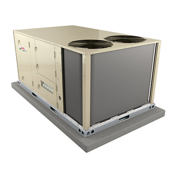
The LCH092H, 094U, 102H, 120H, 122U, 150S, 150H and
152Uunits are configure to order units (CTO) with a wide
selection of factory installed options.
Cooling capacities range from 7.5 to 12.5 tons (38.1 to
70.3 kW). All units are equipped with two compressors.
Optional electric heat is factory-or field-installed. Electric
heat operates in single or multiple stages depending on the
kW input size. 7.5kW to 45kW heat sections are available
for the 092 & 102 and 15kW to 60kW heat sections are
available for 120 &150.
Ultra-high efficiency units are available with an optional di
rect drive blower or belt drive blower equipped with a sup
ply air inverter. Standard and high efficiency units are
available with a belt drive blower equipped with an option
al supply air inverter. The blower will operate at lower
speeds when demand is low and increase to higher
speeds when demand is high.
Standard and high efficiency units come standard with a
lightweight, all-aluminum condenser coil; optional, fin/
tube condenser coils are available. Ultra-high efficiency
units come standard with a tube/fin condenser coil.
Ultra high efficiency units come standard with two single-
speed compressors plumbed in tandem to form a single re
frigerant circuit.
All LCH units are designed to accept any of several different
energy management thermostat control systems with mini
mum field wiring. Factory or field provided control options
connect to the unit with jack plugs. When "plugged in" the
controls become an integral part of the unit wiring.
Information contained in this manual is intended for use by
qualified service technicians only. All specifications are
subject to change. Procedures outlined in this manual are
presented as a recommendation only and do not super
sede or replace local or state codes.
If the unit must be lifted for service, rig unit by attaching four
cables to the holes located in the unit base rail (two holes at
each corner). Refer to the installation instructions for the
proper rigging technique.
WARNING
Improper installation, adjustment, alteration, service
or maintenance can cause property va, personal in
jury or loss of life. Installation and service must be
performed by a licensed professional HVAC installer
or equivalent, service agency, or the gas supplier
Corp. 1009-L7
Revised 05/2020
LCH092 through 152U
Options / Accessories 092/150
Specification 092/150
Options / Accessories 094/152
Specifications 094/152
Blower Tables
Electrical / Electric Heat Data 092 / 150
V System Service Checks
VI Accessories
X Wiring and Operation Sequence
As with any mechanical equipment, contact with
sharp sheet metal edges can result in personal in
jury. Take care while handling this equipment and
wear gloves and protective clothing.
LCH SERIES
7.5 to 12.5 ton
38.1 to 70.3 kW
Table of Contents
. . . . . . . . . . . . . . . . . .
. . . . . . . . . . . . . . . . . . . . . . . . . .
. . . . . . . . . . . . . . . . . .
. . . . . . . . . . . . . . . . . . . . . . . . .
. . . . . . . . . . . . . . . . . . . . . . . . . . . . . . . . .
. . . . . . . . . . . . . . . . . . . . . . . .
. . . . . . . . . . . . . . . . . . . . . . . . . . . .
. . . . . . . . . . . . . . . . . . . . . . . . . . . .
. . . . . . . . . . . . . . . . . . . .
. . . . . . . . . . . . . . . . . . . . . . . . . . . . . . . . . . .
. . . . . . . . . . . . . . . . . . . . . . . . .
. . . . . . . . . . . . . . . . . . . . .
. . . . . . . . . . . . . . . . . . . . . . . . . . . . . .
. . . . . . . . . . . . . . . .
. . . . . . . . . . . . . .
. . . . . . . . . . . . . . . . .
. . . . . . . . . . . . . . .
CAUTION
WARNING
Electric shock hazard. Can cause injury
or death. Before attempting to perform
any service or maintenance, turn the
electrical power to unit OFF at discon
nect switch(es). Unit may have multiple
power supplies.
2
6
8
13
15
. . . . . . . . . .
20
. . . . . . . . .
24
30
31
32
50
50
56
57
57
64
66
68
69
Advertisement
Table of Contents

Related Manuals for Lennox LCH092H


Summary of Contents for Lennox LCH092H
-
Page 1: Table Of Contents
Revised 05/2020 Service Literature LCH092 through 152U The LCH092H, 094U, 102H, 120H, 122U, 150S, 150H and 152Uunits are configure to order units (CTO) with a wide selection of factory installed options. Cooling capacities range from 7.5 to 12.5 tons (38.1 to 70.3 kW). - Page 2 OPTIONS / ACCESSORIES Unit Model No Model Catalog Item Description Number Number 092 102 120 150 COOLING SYSTEM Condensate Drain Trap PVC - C1TRAP20AD2 76W26 Copper - C1TRAP10AD2 76W27 Conventional Fin/Tube Condenser Coil (replaces Environ Coil System) Factory Corrosion Protection Factory Drain Pan Overflow Switch E1SNSR71AD1...
- Page 3 OPTIONS / ACCESSORIES Unit Model No Model Catalog Item Description Number Number 092 102 120 150 CONTROLS Blower Proving Switch C1SNSR35FF1 53W65 Commercial Controls Prodigy Control System - BACnet Module - C0CTRL60AE1L 59W51 ® ® Prodigy Control System - LonTalk Module - C0CTRL65FF1 54W27 ®...
- Page 4 OPTIONS / ACCESSORIES Unit Model No Model Catalog Item Description Number Number 092 102 120 150 ELECTRIC HEAT 7.5 kW 208/230V-3ph - C1EH0075B-1Y 56W38 460V-3ph - C1EH0075B-1G 56W39 575V-3ph - C1EH0075B-1J 56W40 15 kW 208/230V-3ph - C1EH0015B-1Y 56W41 460V-3ph - C1EH0150B-1G 56W42 575V-3ph - C1EH0150B-1J 56W43...
- Page 5 OPTIONS / ACCESSORIES Unit Model No Model Catalog Item Description Number Number 092 102 120 150 ROOF CURBS Hybrid Roof Curbs, Downflow 8 in. height C1CURB70B-1 11F54 14 in. height C1CURB71B-1 11F55 18 in. height C1CURB72B-1 11F56 24 in. height C1CURB73B-1 11F57 Adjustable Pitch Curb...
- Page 6 SPECIFICATIONS General Data Nominal Tonnage 7.5 Ton 7.5 Ton 8.5 Ton 8.5 Ton Model Number LCH092H4B LCH092H4M LCH102H4B LCH102H4M Efficiency Type High High High High Blower Type Constant Air MSAV® (Multi- Constant Air MSAV® (Multi- Volume CAV Stage Air Volume) Volume CAV Stage Air Volume) Cooling...
- Page 7 SPECIFICATIONS General Data Nominal Tonnage 10 Ton 10 Ton 12.5 Ton 12.5 Ton Model Number LCH120H4B LCH120H4M LCH150H4B LCH150H4M Efficiency Type High High High High Blower Type Constant Air MSAV® (Multi- Constant Air MSAV® (Multi- Volume (CAV) Stage Air Volume) Volume (CAV) Stage Air Volume) Cooling...
- Page 8 OPTIONS / ACCESSORIES Unit Model No Model Catalog Item Description Number Number COOLING SYSTEM Condensate Drain Trap PVC - C1TRAP20AD2 76W26 Copper - C1TRAP10AD2 76W27 Corrosion Protection Factory Drain Pan Overflow Switch E1SNSR71AD1 68W88 Refrigerant Type R-410A BLOWER - SUPPLY AIR Blower DirectPlus™...
- Page 9 OPTIONS / ACCESSORIES Unit Model No Model Catalog Item Description Number Number CONTROLS Blower Proving Switch C1SNSR35FF1 53W65 Commercial Controls L Connection Building Automation System Factory ® Prodigy Control System - BACnet Module - C0CTRL60AE1L 59W51 ® ® Prodigy Control System - LonTalk Module - C0CTRL65FF1 54W27 ®...
- Page 10 OPTIONS / ACCESSORIES Unit Model No Model Catalog Item Description Number Number ELECTRIC HEAT - DIRECT DRIVE UNITS 7.5 kW 208/230V-3ph - E1EH0075BP1Y 10U96 460V-3ph - E1EH0075BP1G 10U97 575V-3ph - E1EH0075BP1J 11J19 15 kW 208/230V-3ph - E1EH0150BP1Y 10U99 460V-3ph - E1EH0150BP1G 10X01 575V-3ph - E1EH0150BP1J 10X02...
- Page 11 OPTIONS / ACCESSORIES Unit Model No Model Catalog Item Description Number Number ECONOMIZER Standard Economizer (Not for Title 24) Standard Economizer E1ECON15B-1 55W05 Downflow or Horizontal - Includes Outdoor Air Hood and Downflow Barometric Relief Dampers with Exhaust Hood Order Horizontal Barometric Relief Dampers separately High Performance Economizer (Approved for California Title 24 Building Standards / AMCA Class 1A Certified) High Performance Economizer E1ECON17B-1...
- Page 12 OPTIONS / ACCESSORIES Unit Model No Model Catalog Item Description Number Number ROOF CURBS Hybrid Roof Curbs, Downflow 8 in. height C1CURB70B-1 11F54 14 in. height C1CURB71B-1 11F55 18 in. height C1CURB72B-1 11F56 24 in. height C1CURB73B-1 11F57 Adjustable Pitch Curb 14 in.
- Page 13 SPECIFICATIONS - DIRECTPLUS™ (DIRECT DRIVE) MODELS General Data Nominal Tonnage 7.5 Ton 10 Ton 12.5 Ton Model Number LCH094U4E LCH122U4E LCH152U4E Efficiency Type Ultra Ultra Ultra Blower Type MSAV (Multi-Stage Air MSAV (Multi-Stage Air MSAV (Multi-Stage Air Volume) DirectPlus™ Volume) DirectPlus™ Volume) DirectPlus™...
- Page 14 SPECIFICATIONS - BELT DRIVE MODELS General Data Nominal Tonnage 7.5 Ton 10 Ton 12.5 Ton Model Number LCH094U4M LCH122U4M LCH152U4M Efficiency Type Ultra Ultra Ultra Blower Type MSAV (Multi-Stage Air MSAV (Multi-Stage Air MSAV (Multi-Stage Air Volume) Volume) Volume) Belt Drive Belt Drive Belt Drive Cooling Performance...
- Page 15 BLOWER DATA - DIRECTPLUS™ (DIRECT DRIVE) - ALL ULTRA MODELS BLOWER TABLE INCLUDES RESISTANCE FOR BASE UNIT ONLY (NO HEAT SECTION) WITH DRY INDOOR COIL AND AIR FILTERS IN PLACE. FOR ALL UNITS ADD: 1 − Wet indoor coil air resistance of selected unit. 2 −...
- Page 16 BLOWER DATA - BELT DRIVE - 7.5 TON (092 / 094 / 102) BELT DRIVE BLOWER − BASE UNIT BLOWER TABLE INCLUDES RESISTANCE FOR BASE UNIT ONLY (NO HEAT SECTION) WITH DRY INDOOR COIL AND AIR FILTERS IN PLACE. FOR ALL UNITS ADD: 1 −...
- Page 17 BLOWER DATA - BELT DRIVE - 10 AND 12.5 TON (120 / 122 / 150 / 152) BELT DRIVE BLOWER − BASE UNIT BLOWER TABLE INCLUDES RESISTANCE FOR BASE UNIT ONLY (NO HEAT SECTION) WITH DRY INDOOR COIL AND AIR FILTERS IN PLACE.
- Page 18 BLOWER DATA ALL MODELS FACTORY INSTALLED BELT DRIVE KIT SPECIFICATIONS Motor Efficiency Nominal Drive Kit Number RPM Range Standard & High 590 - 890 Standard & High 800 - 1105 Standard & High 795 - 1195 Standard 730 - 970 Standard 940 - 1200 Standard...
- Page 19 BLOWER DATA ALL MODELS CEILING DIFFUSERS AIR RESISTANCE - in. w.g. RTD11 Step-Down Diffuser Unit Size FD11 Flush Diffuser Air Volume 1 Side, 2 Ends All Ends & Sides 2 Ends Open Open Open 2400 0.21 0.18 0.15 0.14 2600 0.24 0.21 0.18...
-
Page 20: Electrical/Electric Heat Data
ELECTRICAL/ELECTRIC HEAT DATA 7.5 TON 7.5 TON HIGH EFFICIENCY (R-410A) LCH092H4 Voltage - 60hz 208/230V - 3 Ph 460V - 3 Ph 575V - 3 Ph Compressor 1 Rated Load Amps 11.6 Locked Rotor Amps Compressor 2 Rated Load Amps 11.6 Locked Rotor Amps Outdoor Fan... -
Page 21: Electrical / Electric Heat Data 0942
ELECTRICAL/ELECTRIC HEAT DATA 8.5 TON 8.5 TON HIGH EFFICIENCY (R-410A) LCH102H4 Voltage - 60hz 208/230V - 3 Ph 460V - 3 Ph 575V - 3 Ph Compressor 1 Rated Load Amps Locked Rotor Amps Compressor 2 Rated Load Amps Locked Rotor Amps Outdoor Fan Full Load Amps Motors (2) - Page 22 ELECTRICAL/ELECTRIC HEAT DATA 10 TON 10 TON HIGH EFFICIENCY (R-410A) LCH120H4 Voltage - 60hz 208/230V - 3 Ph 460V - 3 Ph 575V - 3 Ph Compressor 1 Rated Load Amps Locked Rotor Amps 38.9 Compressor 2 Rated Load Amps 38.9 Locked Rotor Amps Outdoor Fan...
- Page 23 ELECTRICAL/ELECTRIC HEAT DATA 12.5 TON 12.5 TON HIGH EFFICIENCY (R-410A) LCH150H4 Voltage - 60hz 208/230V - 3 Ph 460V - 3 Ph 575V - 3 Ph Compressor 1 Rated Load Amps 19.6 Locked Rotor Amps 66.1 55.3 Compressor 2 Rated Load Amps 22.4 10.6 Locked Rotor Amps...
- Page 24 ELECTRICAL/ELECTRIC HEAT DATA 7.5 TON DIRECTPLUS™ (DIRECT DRIVE) LCH094U4E Voltage - 60hz 208/230V - 3 Ph 460V - 3 Ph 575V - 3 Ph Compressor 1 Rated Load Amps 13.1 Locked Rotor Amps 83.1 Compressor 2 Rated Load Amps 13.1 Locked Rotor Amps 83.1 Outdoor Fan...
- Page 25 ELECTRICAL/ELECTRIC HEAT DATA 10 TON DIRECTPLUS™ (DIRECT DRIVE) LCH122U4E Voltage - 60hz 208/230V - 3 Ph 460V - 3 Ph 575V - 3 Ph Compressor 1 Rated Load Amps Locked Rotor Amps 38.9 Compressor 2 Rated Load Amps Locked Rotor Amps 38.9 Outdoor Fan Full Load Amps...
- Page 26 ELECTRICAL/ELECTRIC HEAT DATA 12.5 TON DIRECTPLUS™ (DIRECT DRIVE) LCH152U4E Voltage - 60hz 208/230V - 3 Ph 460V - 3 Ph 575V - 3 Ph Compressor 1 Rated Load Amps 19.6 Locked Rotor Amps 66.1 55.3 Compressor 2 Rated Load Amps 19.6 Locked Rotor Amps 66.1...
- Page 27 ELECTRICAL/ELECTRIC HEAT DATA 7.5 TON BELT DRIVE LCH094U4M Voltage - 60hz 208/230V - 3 Ph 460V - 3 Ph 575V - 3 Ph Compressor 1 Rated Load Amps 13.1 Locked Rotor Amps 83.1 Compressor 2 Rated Load Amps 13.1 Locked Rotor Amps 83.1 Outdoor Fan Full Load Amps...
- Page 28 ELECTRICAL/ELECTRIC HEAT DATA 10 TON BELT DRIVE LCH122U4M Voltage - 60hz 208/230V - 3 Ph 460V - 3 Ph 575V - 3 Ph Compressor 1 Rated Load Amps 16.5 Locked Rotor Amps 38.9 Compressor 2 Rated Load Amps Locked Rotor Amps 38.9 Outdoor Fan Full Load Amps...
- Page 29 ELECTRICAL/ELECTRIC HEAT DATA 12.5 TON BELT DRIVE LCH152U4M Voltage - 60hz 208/230V - 3 Ph 460V - 3 Ph 575V - 3 Ph Compressor 1 Rated Load Amps 19.6 Locked Rotor Amps 66.1 55.3 Compressor 2 Rated Load Amps 19.6 Locked Rotor Amps 66.1 55.3...
-
Page 30: Electric Heat Capacities
ELECTRIC HEAT CAPACITIES 7.5 kW 15 kW 22.5 kW 30 kW 45 kW 60 kW Volts Btuh No. of Btuh No. of Btuh No. of Btuh No. of Btuh No. of Btuh No. of Input Input Output Stages Input Output Stages Input Output... -
Page 31: Parts Arrangement
PARTS ARRANGEMENT - 092H, 102H, 120H, 150S, 150H BLOWER REHEAT COIL EVAPORATOR MOTOR (Hot Gas Reheat COIL CONDENSER FANS CONDENSER Units Only) FILTERS COILS (FOUR - 20 X 25 X 2") UNIT CONTROLLER BLOWER ECONOMIZER (OPTIONAL) DISCONNECT / CIRCUIT BREAKER (FACTORY OR FIELD L L E E L L E E... - Page 32 CONTROL BOX PARTS ARRANGEMENT - Standard & High Efficiency Units T43 REHEAT CONTROL COMPRESSOR 2 BLOWER TRANSFORMER TRANSFORMER CONTACTOR CONTACTOR EXHAUST FAN RELAY OUTDOOR FAN 1 RELAY BLOWER MOTOR OVERLOAD RE OUTDOOR LAY SWITCH FAN 2 RELAY COMPRESSOR 1 K125 CONTACTOR HEAT SHUTOFF...
- Page 33 CONTROL BOX PARTS ARRANGEMENT - Ultra High Efficiency Units K3 BLOWER CONTACTOR (BELT DRIVE BLOWERS, WITH INVERTER AND BYPASS OPTION) OR TB13 TERMINAL STRIP (BELT DRIVE BLOW ERS, WITH INVERTER, NO BYPASS OPTION T43 CONTROL CONTROL COMPRESSOR 2 AND DIRECT DRIVE BLOWERS) TRANSFORMER TRANSFORMER CONTACTOR...
-
Page 34: I Unit Components
I-UNIT COMPONENTS 4-Compressor Contactor K1, K2 All compressor contactors are three‐pole, double‐break All 7.5 through 12.5 ton (38.1 through 70.3 kW) units are contactors with 24VAC coils. In all LCH units, K1 and K2 configure to order units (CTO). The LCH unit components (both energized by A55) energize compressors B1 and B2. - Page 35 9-Compressor Overload Relays S176, S177 13-VFD Controller (GP board) A133 (VFD (M-volt CE units) units) Relays are wired in series with the appropriate compres M2 and earlier versions of Unit Controller only. The GP sor contactor and monitor the current flow to the compres board A133 controls and monitors the status of the VFD sor motor.
- Page 36 LINE VOLTAGE IN TELEMECANIQUE OVERLOAD RELAY TRIP CLEAR INDICATION COVER WINDOW DETAIL SHOWING RESET BUTTON (SHOWN ADJUSTED TO MANUAL POSITION CLOSED) AMP SETTING Lift clear cover and turn adjustment screw STOP POINTER counterclockwise. Reset screw will pop out BUTTON when pointer is in M (manual position). Close (RED) cover to lock reset screw into position.
- Page 37 PLUMBING, COMPRESSOR AND REFRIGERANT CIRCUITS DETAIL Standard Efficiency / Fin Tube Coil OUTDOOR COIL STAGE 1 INDOOR COIL STAGE 2 OUTDOOR INDOOR COIL COIL STAGE 2 STAGE 1 DRIERS COMPRESSOR COMPRESSOR S87 LOW EXTERNAL THERMAL S88 LOW PRESSURE PROTECTOR S-5 PRESSURE SWITCH (SOME MODELS)
- Page 38 PLUMBING, COMPRESSOR AND REFRIGERANT CIRCUITS DETAIL High Efficiency All-Aluminum Outdoor Coil INDOOR COIL STAGE 2 DRIERS INDOOR COIL STAGE 1 OUTDOOR COIL STAGE 2 COMPRESSOR OUTDOOR COIL STAGE 1 COMPRESSOR S7 HIGH S4 HIGH PRESSURE PRESSURE SWITCH SWITCH S87 LOW PRESSURE S88 LOW SWITCH...
- Page 39 PLUMBING, COMPRESSOR AND REFRIGERANT CIRCUITS DETAIL Ultra High Efficiency Units With Fin/Tube Coil LIQUID LINE LIQUID LINE DISCHARGE LINE DISCHARGE LINE INDOOR COIL DRIER OUTDOOR COILS COMPRESSOR (1 CIRCUIT) COMPRESSOR COMMON COMMON DISCHARGE LINE SUCTION LINE A185 PRESSURE COMPRESSOR 2 HIGH TRANSDUCER TEMPERATURE LIMIT LOW PRESSURE...
- Page 40 B-Cooling Components Each compressor is energized by a corresponding com pressor contactor. Standard and high efficiency units use independent cooling NOTE-Refer to the wiring diagram section for specific unit circuits consisting of separate compressors, condenser coils operation. and evaporator coils. See figure 10 or 11. Ultra high efficien If Interlink compressor replacement is necessary, call cy units use a common cooling circuit consisting of two 1-800-453-6669.
- Page 41 The A55 Unit Controller has a three-strike counter before 7-Service Valve (optional) locking out. This means the control allows three high LCH units may be equipped with service valves located pressure trips per one thermostat demand. The control in the discharge and liquid lines. The service valves are can be reset by breaking and remaking the thermostat manually operated valves used for service operation.
- Page 42 2 Read the voltage at the appropriate high voltage fan 11-Temperature Sensors RT37 and RT38 motor plug (J86, J87, or J88) using the VAC meter set Ultra high efficiency units are equipped with a temperature ting. sensor (thermistor) located on the back of each compres 3 If high voltage is present, check the low voltage plug sor underneath the crankcase heater.
- Page 43 C-Blower Compartment STANDARD BLOWER ASSEMBLY TO INCREASE BELT TENSION SIDE VIEW 1- Loosen four bolts securing motor mounting base to frame. 2- Turn adjusting bolt to the right, or clockwise, to move the motor away from the blower housing. MOTOR ALLEN SCREW IMPORTANT - Gap between end of frame and motor...
- Page 44 DIRECT DRIVE BLOWER ASSEMBLY BLOWER HOUSING BLOWER MOTOR SECURED TO THIS SIDE OF HOUSING REMOVE TWO SCREWS ON EACH SIDE TO SLIDE BLOWER OUT OF UNIT INLET GRID FIGURE 16 The blower compartment is located between the evapora 1-Blower Wheels tor coil and the condenser coil section.
- Page 45 alarm and the unit will not start. If line voltage is corrected, Determining Unit Air Volume the Unit Controller will energize the unit after five (default) IMPORTANT - VFD units are factory-set to run the blower minutes. While line voltage is continually checked by the at full speed when there is a blower (G) demand without a Unit Controller, the voltage phasing is not.
- Page 46 LOCATION OF STATIC PRESSURE READINGS INSTALLATIONS WITH DUCTWORK INSTALLATIONS WITH CEILING DIFFUSERS ROOFTOP UNIT ROOFTOP UNIT RETURN AIR READING LOCATION RETURN AIR READING RE RE SUPPLY SUPPLY LOCATION TURN TURN FIRST BRANCH OFF OF MAIN RUN MAIN DUCT RUN SUPPLY AIR SUPPLY AIR READING READING...
- Page 47 Check Belt Tension MEASURE BELT TENSION Overtensioning belts shortens belt and bearing life. Check belt tension as follows: 1 Measure span length X. See figure 19. 2 Apply perpendicular force to center of span (X) with enough pressure to deflect belt 1/64” for every inch of FORCE span length or 1.5mm per 100mm of span length.
- Page 48 D-Electric Heat Components the back panel of the electric heat section below the heating elements. The thermostat is wired in series with the first stage contactor coil. When either S15 or See ELECTRICAL / ELECTRIC HEAT DATA and ELEC S19 opens, indicating a problem in the system, contac TRIC HEAT CAPACITIES (table of contents) for electric tor K15 is de‐energized.
- Page 49 ELECTRIC HEAT HEATING ELEMENTS SECONDARY HE1 - HE6 LIMIT S20 SECONDARY SECONDARY LIMIT S20 LIMIT S20 ELECTRIC HEAT VESTIBULE SECONDARY LIMIT S20 SECONDARY LIMIT S20 SECONDARY LIMIT S20 ELECTRIC HEAT THERMOSTAT PRIMARY ELECTRIC HEAT LIMIT CONTROL WIRE HARNESS FIGURE 20 ELECTRIC HEAT TERMINAL STRIP FUSE F3...
-
Page 50: Placement And Installation
TABLE 3 ELECTRIC HEAT SECTION FUSE RATING FUSE (3 each) EHA QUANTITY VOLTAGES & SIZE F3 - 1 F3 - 2 F42 - 1 F42 - 2 208/230 25 Amp 250V 15 Amp 600V EHO075-1, 7.5 10 Amp 600V 208/230 50 Amp 250V 25 Amp 600V EHO150-1, 15... - Page 51 TABLE 4 LGH/LCH092H Normal Operating Pressures - All-Aluminum - TXV Outdoor Coil Entering Air Temperature 65 °F 75 °F 85 °F 95 °F 105 °F...
- Page 52 TABLE 5 LGH/LCH102H Normal Operating Pressures - All-Aluminum - TXV Outdoor Coil Entering Air Temperature 65 °F 75 °F 85 °F 95 °F 105 °F 115 °F Suct Disc Suct Disc Suct Disc Suct Disc Suct Disc Suct Disc (psig) (psig) (psig) (psig)
- Page 53 B-Refrigerant Charge and Check - Fin/Tube Coil - TXV TABLE 9 LCH092H Fin/Tube Coil Hot Gas Reheat - TXV LCH092H, 102H, 120H, 150S, 150H WARNING-Do not exceed nameplate charge under any CIRCUIT 1 CIRCUIT 2 Outdoor condition. Dis Dis Coil...
- Page 54 TABLE 14 3 The approach method is not valid for grossly over or LCH150S Fin/Tube Coil - TXV undercharged systems. Use tables 8 through 17 as a CIRCUIT 1 CIRCUIT 2 guide for typical operating pressures. Outdoor Dis Dis Coil TABLE 18 Suction Suction...
- Page 55 go below the target liquid temperature when adjusting liquid temperature is 96°F. For a measured liquid tem charge. Note that suction pressure can change as perature of 106°F, add charge in increments until mea charge is adjusted. sured liquid temperature agrees with the target liquid temperature.
-
Page 56: Start Up - Operation
1155 F Apply power to unit. F-Charge Verification - Approach Method - AHRI Testing LCH092H, 102H, 120H and 150S, 150H (Figure 22 or 23) (Fin/Tube Coil Continued) 1 Initiate first and second stage cooling demands ac 1 Using the same thermometer, compare liquid tempera... - Page 57 3 Check amp-draw on both condenser fan motor and REFRIGERANT STAGES - blower motor. All-Aluminum Coil Fan Motor Rating Plate ____ Actual ________ (BOTH FANS ARE ENERGIZED WITH A Y1 DEMAND) Indoor Blower Motor Rating Plate____ Actual____ CONDENSER VI-ACCESSORIES FAN 1 The accessories section describes the application of most of CONDENSER CONDENSER...
- Page 58 ASSEMBLED ROOF MOUNTING FRAME TYPICAL FLASHING DETAIL UNIT BASE BOTTOM SUPPLY AIR OPENING UNIT BASE RAIL RETURN AIR OPENING FIBERGLASS INSULATION (Furnished) COUNTER FLASHING (Field Supplied) NAILER STRIP (Furnished) CANT STRIP (Field Supplied) RIGID INSULATION (Field Supplied) FIGURE 25 ROOF MOUNTING FRAME ROOFING (Extends around entire...
- Page 59 OUTDOOR AIR DAMPER COVER PANEL MANUAL DAMPER HORIZONTAL SUPPLY AIR OPENING COMPRESSOR HORIZONTAL SECTION RETURN AIR OPENING LOWER PANEL FIGURE 28 NOTE - All free cooling modes of operation will modu E-Economizer E1ECON15 (standard) or E1ECON17 (high performance) late dampers to 55_F (13_C) supply / discharge air. The following is a brief description of standard economizer Unit Controller Settings E1ECON15.
- Page 60 TABLE 24 ECONOMIZER MODES AND SETPOINT Free Field- ° Free Cooling Dampers will modulate to 55 F (default, parameter 159) Cooling Provided Input Ranges Setpoint discharge air (RT6) when outdoor air is suitable: Mode Sensors Outdoor air temperature (RT17) is less than return air temperature (RT16) °...
- Page 61 F-Gravity Exhaust Dampers H-Control Systems The A55 Unit Controller provides all control function for the LAGEDH03/15 dampers (figure 30) are used in downflow rooftop unit. Default operation requires a standard room and horizontal air discharge applications. Horizontal thermostat or direct digital controller (DDC). The A55 can gravity exhaust dampers are installed in the return air also control the unit from a zone temperature sensor.
- Page 62 N-Factory Installed-Hot Gas Reheat (option) Check-Out General Test Hot Gas Reheat operation using the following proce Hot Gas Reheat units provide a dehumidifying mode of op dure. eration. These units contain a reheat coil adjacent to and 1 Make sure reheat is wired as shown in wiring section. downstream of the evaporator coil.
- Page 63 REHEAT MODE REFRIGERANT ROUTING RETURN OUTDOOR STAGE 2 EVAPORATOR COIL CONDENSER FANS STAGE 1 EVAPORATOR COIL EXPANSION REHEAT STAGE 2 VALVE COIL CONDENSER COIL SUPPLY REHEAT STAGE 1 VALVE CONDENSER COIL STAGE 1 COMPRESSOR STAGE 2 CHECK COMPRESSOR VALVE FIGURE 32 COOLING MODE REFRIGERANT ROUTING RETURN OUTDOOR...
-
Page 64: Belt Drive Supply Air Inverter
VII-Belt Drive Supply Air Inverter M2 Unit Controllers: NOTE - Units equipped a Variable Frequency Drive (VFD) Data > Status > Blower are designed to operate on balanced, three-phase power. M3 Unit Controllers: Operating units on unbalanced three-phase power will re duce the reliability of all electrical components in the unit. - Page 65 ADJUST CFM SETTINGS > RTU Options > EDIT PARAMETER > EN TER DATA ID - 9 > MIN DAMPER LOW BLOWER = X.X If a test and balance contractor has not commissioned the unit, use this section to set supply air CFM. Measure the intake air CFM.
-
Page 66: Direct Drive Supply Air Inverter
Caution - Units not equipped with a VFD will be set to Set VIII-Direct Drive Supply Air Inverter tings > Control > MSAV VFD Bypass > None. The blower If a test and balance contractor has not commissioned the motor could be damaged and/or result in product or proper unit, use this section to set supply air CFM. - Page 67 B-Set Damper Minimum Position TABLE 29 MINIMUM AND MAXIMUM CFM To maintain required minimum ventilation air volumes when 094U4E, 122U4E, 152U4E the unit is in the occupied mode, two minimum damper posi Gas Heat Minimum CFM tions must be set. The Unit Controller will open the dampers Unit Gas Heat Size to “Min OCP Blwr Low”...
-
Page 68: Staged Supply Air Operation
IX-Staged Supply Air Operation Compressor 1 On (on ultra high efficiency units, one compressor will operate) This is a summary of cooling operation for both belt and di Blower Cooling Low rect drive blowers. Dampers Minimum Position Note - During a dehumidification demand the blower oper Y2 Demand - ates at the highest speed. - Page 69 X-Wiring Diagrams and Sequence of Operation LCH092/102/120H - CONSTANT SUPPLY AIR, BELT DRIVE BLOWER Page 69...
- Page 70 LCH150H - Y - CONSTANT SUPPLY AIR, BELT DRIVE BLOWER 24 VAC POWER COMPONENT P268 P268 NOTE - IF ANY WIRE IN THIS APPLIANCE IS REPLACED PANEL, MAIN IT MUST BE REPLACED WITH WIRE OF LIKE SIZE, COMPRESSOR 1 J268 J268 RATING, TERMINATION AND INSULATION THICKNESS.
- Page 71 LCH150H - G, J, M - CONSTANT SUPPLY AIR, BELT DRIVE BLOWER 24 VAC POWER COMPONENT P268 P268 NOTE - IF ANY WIRE IN THIS APPLIANCE IS REPLACED PANEL, MAIN IT MUST BE REPLACED WITH WIRE OF LIKE SIZE, COMPRESSOR 1 J268 J268 COMPRESSOR 2...
- Page 72 LCH092/150S & H SEQUENCE OF OPERATION Power: 1 Line voltage through the S48 unit disconnect, TB2 terminal block, or CB10 circuit breaker energizes the T1 trans former. T1 provides 24VAC power to A55 Unit Controller which provides 24VAC to the unit cooling, heating and blower controls.
- Page 73 LCH092/152U STAGED SUPPLY AIR, NO BYPASS, BELT DRIVE BLOWER Page 73...
- Page 74 LCH092/152U SEQUENCE OF OPERATION Power: 1 Line voltage through the S48 unit disconnect, TB2 terminal block, or CB10 circuit breaker energizes the T1 trans former. T1 provides 24VAC power to A55 Unit Controller which provides 24VAC to the unit cooling, heating and blower controls.
- Page 75 ELECTRONIC OR ELECTROMECHANICAL THERMOSTAT 24 V POWER TO M3 THERMOSTAT INPUTS J297A P297 TO R TO G K55*1 J255 J298A P255 TO Y1 OTHER THERMOSTAT SIGNALS REMAIN CONNECTED AS SHOWN ON THE RIGHT. TO PROVIDE SUPERMARKET REHEAT SCHEME USE S86 DEHUMIDISTAT AND K55. J298A J298A P298...
- Page 76 BRWN DESCRIPTION A130 COMPONENT TB37 SENSOR, SOLID STATE ENTHALPY CONTROL, ERS A130 CONTROL, MAIN PANEL LENNOX SENSOR, ENTHALPY INDOOR CONTROL, REMOTE MIN POS (OPT) MOTOR, DAMPER ECONOMIZER MOTOR, EXHAUST DAMPER JACK, UNIT ECONOMIZER JACK, SENSOR OUTDOOR ENTHALPY J104 JACK, SENSOR RETURN AIR ENTHALPY...
- Page 77 LCH092/102/120H STAGED SUPPLY AIR, NO BYPASS, BELT DRIVE BLOWER 24 VAC POWER COMPONENT NOTE - IF ANY WIRE IN THIS APPLIANCE IS REPLACED PANEL, AUTOMATED LOGIC CONTROL (ALC) IT MUST BE REPLACED WITH WIRE OF LIKE SIZE, PANEL, MAIN RATING, TERMINATION AND INSULATION THICKNESS. CONTROL INVERTER COMPRESSOR 1 DISCONNECT ALL POWER BEFORE SERVICING!
- Page 78 LCH150H - Y - STAGED SUPPLY AIR, NO BYPASS, BELT DRIVE BLOWER COMPONENT 24 VAC POWER PANEL, AUTOMATED LOGIC CONTROL (ALC) NOTE - IF ANY WIRE IN THIS APPLIANCE IS REPLACED PANEL, MAIN IT MUST BE REPLACED WITH WIRE OF LIKE SIZE, CONTROL INVERTER RATING, TERMINATION AND INSULATION THICKNESS.
- Page 79 LCH150H G, J, M - STAGED SUPPLY AIR, NO BYPASS, BELT DRIVE BLOWER COMPONENT 24 VAC POWER PANEL, AUTOMATED LOGIC CONTROL (ALC) NOTE - IF ANY WIRE IN THIS APPLIANCE IS REPLACED PANEL, MAIN IT MUST BE REPLACED WITH WIRE OF LIKE SIZE, CONTROL INVERTER RATING, TERMINATION AND INSULATION THICKNESS.
- Page 80 LCH092/102/120H STAGED SUPPLY AIR, WITH BYPASS, BELT DRIVE BLOWER COMPONENT 24 VAC POWER PANEL, AUTOMATED LOGIC CONTROL (ALC) NOTE - IF ANY WIRE IN THIS APPLIANCE IS REPLACED PANEL, MAIN IT MUST BE REPLACED WITH WIRE OF LIKE SIZE, CONTROL INVERTER RATING, TERMINATION AND INSULATION THICKNESS.
- Page 81 LCH150H - Y - STAGED SUPPLY AIR, WITH BYPASS, BELT DRIVE BLOWER COMPONENT 24 VAC POWER PANEL, AUTOMATED LOGIC CONTROL (ALC) NOTE - IF ANY WIRE IN THIS APPLIANCE IS REPLACED PANEL, MAIN IT MUST BE REPLACED WITH WIRE OF LIKE SIZE, CONTROL INVERTER RATING, TERMINATION AND INSULATION THICKNESS.
- Page 82 LCH150H - G, J, M - STAGED SUPPLY AIR, WITH BYPASS, BELT DRIVE BLOWER COMPONENT 24 VAC POWER PANEL, AUTOMATED LOGIC CONTROL (ALC) NOTE - IF ANY WIRE IN THIS APPLIANCE IS REPLACED PANEL, MAIN IT MUST BE REPLACED WITH WIRE OF LIKE SIZE, CONTROL INVERTER RATING, TERMINATION AND INSULATION THICKNESS.
- Page 83 LCH092-152U STAGED SUPPLY AIR, WITH BYPASS, BELT DRIVE BLOWER 24 VAC POWER P268 P268 COMPONENT J268 J268 PANEL, AUTOMATED LOGIC CONTROL (ALC) PANEL, MAIN CONTROL INVERTER COMPRESSOR 1 COMPRESSOR 2 RELAY MOTOR, BLOWER (IDB)PWM 1/VO MOTOR, OUTDOOR FAN 1 MOTOR, OUTDOOR FAN 2 MOTOR, EXHAUST FAN MOTOR, OUTDOOR FAN 3 (ODF)PWM 3...
- Page 84 SUPPLY AIR INVERTER - NO BYPASS SEQUENCE OF OPERATION OPERATION: A96 FAULT SEQUENCE: A55 energizes the K203 relay coil. A96 will interrupt the 0-10VDC signal at terminal 2 on an in ternal failure. A96 will retry three times before terminals B-C K203-2 N.O.
- Page 85 LCH092-152U STAGED SUPPLY AIR, DIRECT DRIVE BLOWER Direct Drive EBM Blower Motor: The blower speed is deter mined by thermostat demand and settings programmed into the A55. When A55 receives a Y1 demand, a low speed volt age output from A55 terminal 4 will energize B3 in low speed. When A55 receives a Y2 demand, a high speed voltage output from A55 terminal 4 will energize B3 in high speed.
- Page 86 DIRECT DRIVE BLOWER SEQUENCE OF OPERATION / TROUBLESHOOTING Blower Operation: Line voltage is routed to B3 blower motor through TB2 terminal strip, TB13 terminal strip, T4 transformer (575v units only), and J/P48 terminals 1, 2 and 3. B3 blower motor runs internal diagnostics to check for proper temperature, voltage, etc. (KL2-2 and -3). This process takes approximately 10 seconds.
- Page 87 TABLE 30 DIRECT DRIVE BLOWER MOTOR TROUBLESHOOTING Failure Error Warning Reason Troubleshoot No changes in hall signals Check for obstruction keeping Locked Rotor • within 2000ms impeller from rotating Warning, no error code set, Check for secondary airflow source in Braking Mode •...
- Page 88 ELECTRIC HEAT FOR LCH092/150 UNITS Page 88...
- Page 89 ELECTRIC HEAT FOR LCH092/150 UNITS Page 89...
- Page 90 SEQUENCE OF OPERATION EHA7.5, 15, 22.5, 30, 45, 60 kW - G, J, M and Y G, J and M Voltage Y Voltage 1 Terminal strip TB3 is energized when the unit discon 1 Terminal strip TB3 is energized when the unit discon nect closes.
Need help?
Do you have a question about the LCH092H and is the answer not in the manual?
Questions and answers