Table of Contents
Advertisement
Quick Links
Advertisement
Table of Contents

Related Manuals for Uninet iCOLOR 900


Summary of Contents for Uninet iCOLOR 900
- Page 1 900 APEX2Print Installation and User Guide...
- Page 2 System Requirements CPU: Intel Xeon E5-1650 @ 3.20GHz, or Intel Core i7-3930K @ 3.20GHz RAM: 12GB RAM (minimum) HDD: 150GB SATA 10K , 15K RPM or SDD OS: Windows 7 Professional, or Ultimate 64-bit Before starting the software installation, you need to ensure that you have a clean version of Windows 7 with nothing installed.
-
Page 3: Table Of Contents
Safety Information ......................8 120 Volt Models ............................8 220/240 Volt Models ..........................9 Introduction to the IColor 900 ..................11 a. Unpacking the Feeder ......................... 11 b. Unpacking and Setting Up the Printer ....................12 Loading Media ......................19 Installing APEX2Print Software .................. - Page 4 Appendix ..........................53 ICOLOR 900 Specifications ........................54 Die Cut Media Instructions ....................55 Feeder Menu Summary ....................... 58 a. Changing Menu Settings ........................58 b. Feeder Error Messages ........................60 Using the Printer Menu ....................... 61 a. Changing Settings ..........................61 b.
- Page 5 Avoiding Paper Jams ..........................96 Correcting Print Quality Defects ................... 97 Removing Glue Residue from the Feeder Unit ..............99 Adjusting Guide Width ...................... 101 Manually Adjusting the Guide Width ................. 109 Uninstalling APEX2Print ..................... 110 Troubleshooting ........................ 112 a. How to Change the Settings: User ....................112 b.
-
Page 6: Limitation Of Liability
1. Limitation of Liability Uninet total liability to the purchaser, or to any third party, for damages from any and all causes whatsoever, regardless of the form of action, whether in contract or in tort, including negligence, and any infringement of proprietary rights or any misappropriation or unlawful use of any proprietary rights or property of any third party shall, in the aggregate, be limited to purchase price actually paid by the purchaser for the product relating to the damages. -
Page 7: Icolor 900 Warranty
Product. A certified Uninet service representative shall perform repairs, and such repairs, at the option of Uninet, may be performed at the customer site, a dealer site, a service depot or the factory. Replacement Product, at the option of Uninet, may be either new or equivalent in performance to new. -
Page 8: Safety Information
3. Safety Information 120 Volt Models Your Uninet product has been carefully designed to give you years of safe, reliable performance. As with all electrical equipment, there are a few basic precautions you should take to avoid hurting yourself or damaging the product. -
Page 9: 220/240 Volt Models
If the product casing gets extremely hot or smoke, unusual smells or abnormal noises are emitted from the product, there is a risk of fire. Unplug the mains connector and contact your Uninet. If the product has been knocked over or damaged, there is a risk of electric shock, fire and/or injury. Unplug the mains connector and contact Uninet. - Page 10 Do not introduce foreign objects into the ventilation holes or operate this product with any covers open or doors removed as electric shock, fire and/or injuries may occur. Do not use an extremely flammable spray near the product as the product contains high temperature parts that may cause a fire.
-
Page 11: Introduction To The Icolor 900
Unpacking the Feeder 4. Introduction to the IColor 900 STEP 1 of 4 STEP 2 of 4 Cut the ties and remove the tape from the box. Lift the top sleeve upwards exposing the feeder. STEP 3 of 4... -
Page 12: Unpacking And Setting Up The Printer
b. Unpacking and Setting Up the Printer STEP 1 of 23 STEP 2 of 23 Cut the ties and remove the tape from the Remove the top sleeve. printer box. STEP 3 of 23 STEP 4 of 23... - Page 13 Remove the accessory box and corner pieces. Using two or three people, lift the printer and place it on the feeder, making sure the printer is level on the feeder.
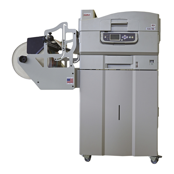
- Page 14 STEP 5 of 16 STEP 6 of 16 When placing the printer on the feeder, ensure ICOLOR 900 should be similar to this diagram when you are aligning the printer with the pins located full assembled. on the top back of the feeder.
- Page 15 Check all the components are present before assembling: (1) Printer (2) Light-shield bags, paper tray media labels, LED lens cleaning pad (3) Power Cable (4) Ferrite Core (5) CD (includes User Guide, Warranties, and Drivers) (6) Toner Cartridges STEP 7 of 23 STEP 8 of 23 Remove any shipping tape.
- Page 16 STEP 10 of 23 STEP 11 of 23 Remove colored image drum packing pieces. Remove tape DO NOT remove the actual image drums. STEP 12 of 23 STEP 13 of 23 Remove protective sheet 1. Remove colored locks (b). 2. Remove tape then remove colored seals (a). NOTE: Be sure all tape is removed from image drum cartridges.
- Page 17 STEP 16 of 23 STEP 17 of 23 1. Lock toner cartridge with blue lever. Close the top cover. 2. Repeat these steps for remaining toner cartridges. STEP 18 of 23 STEP 19 of 23 1. Pull out the paper tray (a). Load paper.
- Page 18 STEP 20 of 23 STEP 21 of 23 1. Set guides (a, b) to paper size. Make sure the paper Install the paper catcher. guides are snug against the paper. 1. Lift cover where paper catcher is placed. 2. Close the paper tray (c). 2.
-
Page 19: Loading Media
5. Loading Media IMPORTANT: Use with Media with a maximum width of 12.9" Maximum Print width: 12.6" Cutter Cover Guide Channels Spindle Pin Extension Media Door Guide Door Load Door Identify the three doors and cover for the feeder. - Page 20 STEP 1 of 7 STEP 2 of 7 Open the Media Door. Lift the Extension Arm back up into position making sure both the Plunger and Extension Arm lock. Before loading the roll, ensure the sides of the roll are completely flat.
- Page 21 Open the Guide Channels. Feed the media under the Place the paper evenly between the Guide orange Tension Swing as shown. Channels and hold it steady with one hand. STEP 5 of 7 STEP 6 of 7 Remove cut piece of media. Channel Gap Ensure the Channel Gap (the distance between the Press the Load button to load the media.
-
Page 22: Installing Apex2Print Software
The control panel screen should look like this after a few moments. Press the Done button. The media will then load and the feeder will return to Idle status. 6. Installing APEX2Print Software STEP 1 of 8 Before proceeding with this installation log into your computer with an Administrator account. Navigate to the installation folder provided by your vendor. - Page 23 Navigate to the 2) Install RIP vR2 Folder > Run the Prepare_Uninet_RIP_v2.1.exe file.
- Page 24 STEP 3 of 8 The KEYLOK and Sentinel Drivers will install.
- Page 25 STEP 4 of 8 The Dongles ( ) should be inserted at this stage. Click the “Install Dongles then Click to Continue” button.
- Page 26 STEP 5 of 8 Click Done. STEP 6 of 8...
- Page 27 Navigate to the 3) Install APEX2Print folder> Run the APEX2Print_Install.msi file >Click Next >.
- Page 28 STEP 7 of 8 Click Next > on the Select Installation Folder Window> Click Next on the Confirm Installation Window. STEP 8 of 8 The Installation will proceed. Click Close on the Installation Complete Window.
-
Page 29: Apex2Print Interface
7. APEX2Print Interface 1.Toolbar 2.Preview Screen 3.Print Settings 4.Image List 5.Rip Options Note: Before launching APEX2Print make sure the two dongles are inserted... -
Page 30: First Time Setup
Setting up the IP Addresses 8. First Time Setup In order to connect to the IColor 900, you need two predetermined static IP Addresses and two network cables, one for the printer and feeder. Setting the IP address on the ICOLOR 900... - Page 31 STEP 5 Use the up arrow keys to enter the IP Address, hitting enter to move right to the next column. When a * (asterisk) symbol appears, the IP Address has been saved. Select Online to finish. Write this IP address down as you will need to input it into the software.
-
Page 32: Input Ip Addresses Into Apex2Print
b. Input IP addresses into APEX2Print. STEP 1 Step 2 Input the IP Addresses that were setup for the From the APEX2Print toolbar click on Setup Options Printer and Feeder> Click Save. > IP Addresses. c. Selecting a Media ID STEP 1... - Page 33 To select the media of choice, click Media tab on the APEX2Print toolbar> Select the correct Media ID you are using and double click on that Media ID to use the predefined settings required for using that specific media type. *To create or edit custom media please refer to the appendix...
-
Page 34: Setting Up The Cost Calculator
d. Setting up the Cost Calculator STEP 1 Step 2 Input the price paid for each consumable. This will From the APEX2Print toolbar click on Setup Options calculate the cost per label. This value will appear > Cost Calculator. in the Image List. -
Page 35: Changing Units Of Measurement
e. Changing Units of Measurement STEP 1 Step 2 From the APEX2Print toolbar click on Setup Options Choose Measurement Units in either Imperial (in.) > Display Options. or Metric (mm). To apply settings click Save. -
Page 36: Changing The Color Registration
f. Changing the Color Registration STEP 1 From the APEX2Print toolbar click on Setup Options > Color Registration. STEP 2 Click Print Registration Plot. - Page 37 STEP 3 The printer will print a similar page that will aid in determining the proper registration values across CMY. Using a printer's loupe, or best judgment, the correct values can be determined. In this case, the correct values are as follows: C:6 M:4 Y:0; this is because the pixels are perfectly filled within the boxes.
- Page 38 STEP 4 With the values determined: C:6 M:4 Y:0. The following adjustments can be made to the Color Registration Form. Click Apply to set.
-
Page 39: How To View Cost Report
g. How to View Cost Report From the APEX2Print toolbar click Cost Report. The Cost Report will be displayed. Notice that 3 PDF files are in the job and each are separately calculated. The TOTAL COST of all jobs is calculated at the bottom of the page along with the TOTAL LENGTH. - Page 40 Job Set #1 -- Column #2 of 3 PDF Name : 2x2_green.pdf Label Size : 2 x 2 in K Percentage = 3.0% C Percentage = 45.5% M Percentage = 8.2% Y Percentage = 57.1% Toner Cost per Label(CMYK) = 0.0148 Total Length Column #2 = 1.77 feet Total Labels To Print = 10 Total Toner Cost(CMYK) = 0.1479...
-
Page 41: Saving And Loading
h. Saving and Loading Page Information STEP 1 The Page Information Settings can be saved and loaded for later use. Click File> Save Page Information> Select a location> Type a file name> Click Save. To Load a Page Information file, click File>... -
Page 42: Before Printing
9. Before Printing a. Measuring your Media Measure Width of Paper, Horizontal and Vertical Gaps between labels (if applicable), and input these values into APEX2Print. Option 1: For Die cut labels with gaps (For Die Cut Media Instructions see Appendix: Die Cut Media Instructions). -
Page 43: Selecting Media
From the toolbar click Media. The following media list will open. This media list holds Medias that have been certified by Uninet. After selecting the type of material and the texture of your media roll, click on the type of media that will be used or match it to the Media ID. -
Page 44: Sensor Calibration
c. Sensor Calibration (for die cut media only) Die cut media with gaps in between labels will use the Gap Sensor. (see Step 2 of 6) Die cut with black lines on the back will use the Back Sensor. Die cut with black lines on the top will use the Top Sensor. (see Step 2 of 6) STEP 1 In APEX2Print select Die Cut Mode. - Page 45 STEP 2 • Select correct sensor according to the type of media being used. • If the calibration sensor is red, you must calibrate the media.
- Page 46 STEP 3 Red Arrow: Where the sensor is located. The media needs to pass through here to be calibrated. Blue arrow: Is the place where the media should be before calibration. For calibrating media that uses the Back and Top sensor, line up the Black Marking on the paper (shown in the photo as the blue arrow) about one inch below the sensor (Red arrow).
- Page 47 STEP 5 Select Run Calibration to start the auto calibration. The printer will run the paper • about 6 inches to the nearest gap or black mark. • To use the values previously stored in the feeder from the last use press Copy Feeder Settings To Media Library.
- Page 48 STEP 6 • After calibration manually rewind the roll until the paper is inside the red arms The feeder will read Require Load. • Press the Load button •...
-
Page 49: Printing
10. Printing a. Adding Label Image The Apex2Print program uses PDF format only. To open a file simply Drag and Drop your PDF image file to the preview screen or you may also choose the Open File button or choose File > Open b. -
Page 50: Printing
d. Printing STEP 1 of 4 Click Open File and select a PDF file or multiple PDF files all of the same dimensions (the selected files will be displayed in the Preview Screen). Notice that multiple files are aligned in columns. Once all PDF files have been added and the entire page Information adjustments have been made click Print. - Page 51 STEP 2 of 4 If a previous media width was used with your feeder, the feeder guide will retain that width. If the new media width is not the same size then the Feeder / Media Size Mismatch window will display. Select OK to Unload Media (If there is no media loaded this action still needs to be completed).
- Page 52 STEP 4 of 4 If Done is not selected on the feeder unit the printer will remain in a busy state and display a Feeder Not Ready window> Press Done on the feeder unit> Click OK.
-
Page 53: Appendix
Appendix... -
Page 54: Icolor 900 Specifications
1. Published performance results based on laboratory testing. Individual results may vary. 2. Must use Narrow Fuser. 3. This product is designed and engineered to operate only with genuine Uninet consumables and certified media substrates. Please contact Uninet for the most current Certified Media List of substrates available. -
Page 55: Die Cut Media Instructions
4. Letter-size sheets at 5% coverage. Printer ships with a 7,500 page set of starter toners. 5. Based on 500 cut-sheet pages/job. Uninet reserves the right to change product specifications without notice. Trademarks are the property of their respective manufacturers. ©2013 Copyright, Uninet. All Rights Reserved. All content is subject to change without notice. - Page 56 In this example we have a die cut with dimensions of 101.9h x 101.9w that we received from a converter. The overprint area is 1mm larger than the actual label on all sides, thus adding 2mm total to the height and 2mm total to the width. This gives us a label image size of 103.9 x 103.9. The gap and alley are each measured at 3.175.
-
Page 58: Feeder Menu Summary
Feeder Menu Summary a. Changing Menu Settings 1. To use the Menu you must first press offline. 2. Press Menu (far right button). Use the Arrow buttons to move up & down through menu items. Press Select. 3. To choose a selection – press Select – you will see a pointer on the left margin that will blink. Press up or down arrow to change options. - Page 59 PAGE 3...
-
Page 60: Feeder Error Messages
If the feeder menu continues to display this error, reload the media and ensure all the proper settings have been set. If you still receive an error message please contact Uninet Service Support by phone 1-866-415-4797, or by email support@Uninet-label.com. -
Page 61: Using The Printer Menu
a. Changing Settings Using the Printer Menu The steps involved in using the menus are typically as follows: 1. Ensure that the display panel indicates that the printer is ready to print. 2. Enter user menu mode by pressing either the Enter button or the Up-arrow or Down-arrow button and press the latter two repeatedly until the desired menu is highlighted in the displayed list. -
Page 62: Display Panel Messages
c. Display Panel Messages MESSAGE COMMENT Ready to Print Your printer is online and ready to print. Printing Your printer is printing and paper is currently being fed from Tray 1 or MP Tray. Near End The paper supply in the tray is low and will run out soon. Toner Low The remaining toner of color is running low. -
Page 63: Setting Media Type For All Print Jobs (Defaults)
• Administrator menu: accessed by pressing the Enter button for more than 2 seconds while turning on the printer power supply (including restart). Available to administrator level users. Restricts the changes that general users can make via the user menus. •... -
Page 64: How To Create And Edit New Media Id/Custom Media Id
How to create and edit new Media ID/Custom Media ID a. Creating New Media STEP 1 of 5 right To create a new media, click Media Tab on the APEX2Print toolbar> Select the correct media ID and click on any Media ID. - Page 65 STEP 2 of 5 The Creating a New User Media Entry window will open. Note: All 3 User Media fields must be filled before a new media entry can be updated into the media list. STEP 3of 5...
- Page 66 Notice that the User Media fields have been filled and the Update/Create This Media button is now available. Make the necessary adjustments to the Media Type field and the Media Weight. Please check the Appendix for a media guide description. When the necessary changes have been made click Update/Create This Media.
-
Page 67: Editing A Newly Created Media Id
STEP 5 of 5 There is an option that allows for only the new media to be displayed. Check the Show Only User Media box to view only new/custom media IDs. b. Editing a newly created Media ID STEP 1 of 4 If the new media entry needs to be edited, right click on the new Media ID... - Page 68 STEP 2 of 4 The Creating a New User Media Entry window will display. Click Edit. STEP 3 of 4...
- Page 69 Make the necessary changes to the User Media fields> Click Update/Create This Media. Notice the Delete This Media button. STEP 4 of 4 To delete a new Media ID, ensure that the media for deletion is not loaded. An Error Deleting Active Media window will display the warning displayed above.
-
Page 70: Replacement Of Consumables And Maintenance
Replacement of Consumables and Maintenance a. Replacing the Fuser STEP 1 STEP 2 CAUTION: The Fuser may be hot. Using the handle, gently Lift the fuser out of the Lift the Blue tab up to unlock the fuser. printer b. Replacing the Transfer Belt STEP 1 STEP 2 Turn off the printer. - Page 71 STEP 3 STEP 4 Remove the four image drums/toner cartridge Cover them with dark paper or plastic to protect them units and place them on a flat surface. from light. STEP 5 STEP 6 Lift the transfer belt latches to release them. Grasp the blue handles and lift the transfer belt out.
-
Page 72: Replacing The Waste Toner Bottle
STEP 9 STEP 10 Put the image drum/toner cartridge units back into 1. Close the top cover. the printer. 2. Turn the Printer on. c. Replacing the Waste Toner Bottle STEP 1 STEP 2 Open the door and remove the waste toner bottle. Follow the instructions on the label to ensure proper disposal. -
Page 73: Cleaning The Led Heads
d. Cleaning the LED Heads Note: Clean the LED heads: • Any time you replace a toner cartridge • If printing is showing signs of faded images, white stripes or blurred letters STEP 1 STEP 2 Open the top cover. Use the LED cleaner provided with the toner cartridges or a soft, lint-free cloth to gently wipe each of the four heads (1). -
Page 74: Printing Options
Printing Options a. Nesting Being able to print multiple images on your current media at the same time. STEP 1 of 10 Click the Nesting Tab. Notice that the Add and Edit buttons have become available and the Print button is now labeled Print Nesting. - Page 75 STEP 2 of 10 From the APEX2Print toolbar click Nesting> Click Open File and select a PDF file, or multiple PDF files of the same dimensions/size (the selected files for nesting will be displayed in the Preview Screen)> Click Add and the PDF/PDFs will be removed from the Preview Screen (The job will be stored for printing).
- Page 76 STEP 3 of 10 From the APEX2Print toolbar click Nesting> Click Open File and select a PDF file, or multiple PDF files of the same dimensions/size (the selected files for nesting will be displayed in the Preview Screen)> Click Add and the PDF/PDFs will be removed from the Preview Screen (The job will be stored for printing).
- Page 77 STEP 4 of 10 Continue to repeat the process in Nesting: Step 1. From the APEX2Print toolbar click Nesting> Click Open File and select a PDF file, or multiple PDF files of the same dimensions/size (the selected files for nesting will be displayed in the Preview Screen)> Click Add and the PDF/PDFs will be removed from the Preview Screen (The job will be stored for printing).
- Page 78 STEP 5 of 10 Notice that 3 jobs have been nested with the Print Nesting: 3 button indicator. If needed, click on Edit to make additional changes to the nested jobs.
- Page 79 STEP 6 of 10 The Nesting Options Window will open. Notice that adjustments can be made to impact the white space of a label, controlling where on the label that jobs are printed. The quantity of labels can also be adjusted across each nested job.
- Page 80 STEP 7 of 10 The job is ready for printing. Click Print Nesting:#.
- Page 81 STEP 8 of 10 If a previous media width was used with your feeder, the Feeder Guide will retain that width. If the new media width is not the same size then the Feeder / Media Size Mismatch window will display. Select OK to Unload Media (If there is no media loaded this action still needs to be completed).
- Page 82 STEP 10 of 10 If Done is not selected on the feeder unit the printer will remain in a busy state and display a Feeder Not Ready window> Press Done on the feeder unit> Click OK.
-
Page 83: Rip Rotate Options
b. Rip Rotate Options STEP 1 When the Rip Rotate Option is set to 0 all PDF files will preview in their original orientation. The Rip Rotate Options will allow for the desired orientation. - Page 84 STEP 2 STEP 3 Select the desired rotation value> Click Clear in the Click Open File>Select the PDF for rotation. Image List section.
- Page 85 STEP 4 The rotation has been applied to the PDF. Adjustments can now be made in the page Information section for correct placement on the Selected Media.
-
Page 86: Rip Scaling Options
c. Rip Scaling Options STEP 1 STEP 2 Select the desired scaling values> Click Clear in the Click Open File> Select the PDF for scaling. Image List section. - Page 87 STEP 3 The Preview Screen will display the scaled object.
-
Page 88: Paper Sensor Error Codes
If the feeder menu continues to display this error, reload the media and ensure all the proper settings have been set. If you still receive an error message please contact Uninet Service Support by phone 1-866-415-4797, or by email support@Uninet-label.com. -
Page 89: (Iv) Feeder Panel Errors
Solution Emergency stop (guide door opened Close Door on Feeder Status: Error 00 during motor movement) Status: Error 01 Switch panel communication error Contact Service: 1-866-415-Uninet (4797) Status: Error 02 Internal error Contact Service: 1-866-415-Uninet (4797) Status: Error 03 Internal error... -
Page 90: (I) Tray Side Cover
(i) Tray Side Cover STEP 1 STEP 2 Hold the tab, turn the paper guide outward. Remove the paper jam. STEP 3 Close the paper guide. -
Page 91: (Ii) Printer Side Cover
(ii) Printer Side Cover STEP 1 STEP 2 Open Side Cover Pull release lever and open side cover. STEP 3 STEP 4 Remove the paper jam. Close the side cover. -
Page 92: (Iii) Printer Top Cover
(iii) Printer Top Cover STEP 1 STEP 2 Squeeze top cover handle Squeeze basket handle and raise drum basket. WARNING: Be careful not to touch the fuser unit which may be hot after printing. If the fuser unit is hot, wait until it cools before attempting to remove any jammed paper. - Page 93 STEP 5 STEP 6 Release levers Pull up jam release levers to release paper Turn the lock lever to lock fuser unit. STEP 7 STEP 8 Open the face-up stacker Open side cover (paper exit)
- Page 94 STEP 9 STEP 10 Close side cover, and then face-up stacker Close image drum basket. STEP 11 Close the top cover.
-
Page 95: (Iv) Roll Paper Jams
(iv) Roll Paper Jams STEP 1 STEP 2 If you have a paper jam, press Help to find out the error Open the Side Cover. code. STEP 3 STEP 4 Locate the paper jam. Open the Guide Door and Guide Cover. Open the two Guide Channels and Load Door. -
Page 96: Avoiding Paper Jams
STEP 5 STEP 6 Open the Media Door of the feeder. Lower the Extension Reload media. Arm. Using both hands, rewind the paper roll until the yellow LED light on the feeder menu begins flashing. At this time, you want to ensure the tension on the paper roll isn’t too tight and the roll isn’t damaged or Avoiding Paper Jams coning. -
Page 97: Correcting Print Quality Defects
Correcting Print Quality Defects SYMPTOMS POSSIBLE CAUSES STEPS TO TAKE Vertical white lines The LED head is dirty. Wipe the LED head with a LED lens cleaner or with a soft can be seen on the cloth. printed page. The toner is low. Replace the toner cartridge. - Page 98 Periphery of the The LED head is dirty. Wipe the LED head with a LED lens cleaner or with a soft letters is smudged. cloth. Toner comes off The thickness and type of Set the correct value of [Media Type] and [Media Weight] when it is rubbed.
-
Page 99: Removing Glue Residue From The Feeder Unit
Removing Glue Residue from the Feeder Unit After printing there may be a build-up of adhesive on the guide arms, extension arms and cutter blade. As a result, the roll will stick and create excess back tension when feeding, causing load failures, bad cuts and unfavorable output. - Page 100 Example #2 – Guide Arms Glue Residue Example #3 – Cutter Blade Glue Residue...
-
Page 101: Adjusting Guide Width
Adjusting Guide Width STEP 1 STEP 2 Feeder control panel should now be back at the Press the Online/Offline button which will cause the Offline screen: feeder to unload the media (it will do this if there is media loaded or not). STEP 3 STEP 4 Once the unload operation is complete, the control... - Page 102 STEP 5 STEP 6 Leave the Guide Arm down. The Extension Arm will automatically adjust to 12.375” wide. This is not wide enough for 12.90” Close the Media Door, and press Done on the control (327.66mm) wide media, so a manual adjustment panel.
- Page 103 STEP 9 STEP 10 Open the Media Door. Insert a roll of 12.90” Lift the Extension Arm back up into position making (327.66mm) paper as shown, ensuring you’re holding sure both the Plunger and Extension Arm lock. the roll on the side and making sure the core is flush with the media.
- Page 104 Open the Guide Cover and Guide Channels. Feed the paper under the orange Tension Swing as shown.
- Page 105 STEP 13 STEP 14 Channel Gap Place the paper three quarters of the way up the Ensure the Channel Gap (the distance between the path so the paper has covered the paper sensors edge of the paper and the Guide Channel) is less than completely.
- Page 106 STEP 15 STEP 16 PRESS and HOLD the Exit button for 3 seconds to exit The control panel should look like this: out of the guide adjust mode. Press the Load button to load the media. Press the Online/Offline button to go back Online. The roll will begin to load and cut off a section for proper alignment.
- Page 107 STEP 17 STEP 18 Remove cut piece of media. The control panel screen should look like this after a Open the Cutter Door and remove the cut piece of few moments: waste paper. Close the Cutter Door. STEP 19 STEP 20 Press the Done button.
- Page 108 STEP 21 Close the Guide Door and the system is ready to print...
-
Page 109: Manually Adjusting The Guide Width
Manually Adjusting the Guide Width Why is this important? When the media is not tight between the guides, there may be movement along the X-axis and result in graphics being out of registration or possible errors in the feeder. Ideally, the Channel Gaps should be less than 0.5mm on each side of the media. -
Page 110: Uninstalling Apex2Print
STEP 3 The status should now be Offline. Press Guide. STEP 4 Select Open or Close to manually adjust the guide to the proper width. Each time open/close is pressed, the guides open 0.01” (0.254mm). Once this is done, select Exit. Note: You may need to open and close the Guide Channels, Load Door and Guide Cover to see how tight the media is between the Guide Channels. - Page 111 STEP 1 of 4 STEP 2 of 4 STEP 3 of 4 STEP 4 of 4 Select APEX2Print> Right Click> Select Uninstall. Click Yes on the window prompt. APEX2Print will uninstall. Start Menu> Control Panel. Click on Programs and Features.
-
Page 112: Troubleshooting
Troubleshooting a. How to Change the Settings: User It should be noted that many of these settings can be, and often are, overridden by settings in the Windows printer drivers. However, several of the driver settings can be left at “Printer Setting”, which will then default to the settings entered in these printer menus. -
Page 113: How To Change The Settings: Administrator
b. How to Change the Settings: Administrator You can set whether to ENABLE or DISABLE each category in the user menu. Disabled categories are not displayed in the User’s menu. Only a system administrator can change these settings. 1. Turn OFF the printer. Turn ON the printer while pressing the Enter button. When Boot Menu appears, take your finger off the button. -
Page 114: Exit Speed Adjustment
c. Exit Speed Adjustment If the image is smearing, increase the exit speed. STEP 1 STEP 2 Select Menu on the printer menu. Scroll down the menu and select Calibration. STEP 3 STEP 4 Scroll down the Calibration menu. Select Exit Speed Adjustment. STEP 5 Adjust the exit speed by increasing the number in increments of two.
Need help?
Do you have a question about the iCOLOR 900 and is the answer not in the manual?
Questions and answers