
Subscribe to Our Youtube Channel
Related Manuals for Uninet iColor LF-600


Summary of Contents for Uninet iColor LF-600
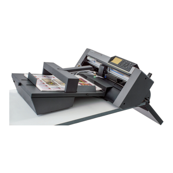
- Page 1 USER MANUAL Uninet LF-600 Digital die cutter for sheet labels this product is certified...
- Page 2 iMark DIGITAL CUTTING SOFTWARE This software has been designed to effectively cut sheet labels. There are also functions for the management of cross cut and hatch. Allows users to import AI and EPS format files. All files have to contain two reference marks. The dedicated video camera connected to the software detects the crop mark in a fraction of a second and adapts the cut path to the inclination and distortion of the print.
- Page 3 CUTTING PLOTTER START UP After you turn on the cutter, you have to do the following: 1. Check and adjust the right pinch rollers position to adapt at the paper width. 2. The left pinch roller is in a fixed position and doesn’t have to be moved, otherwise you would receive an error message on the display of the plotter.
- Page 4 CABLE CONNECTIONS AND AIR ADJUSTMENT The regulation of the vacuum force and the blowers speed are intended to avoid that more than one sheet is picked up by the suction cups. The adhesive paper does not require any attention, you can leave the blower speed at minimum.
- Page 5 PINCH ROLLER POSITION After adjusting the paper guides width with the knob, you have to insert manually one sheet in order to verify the position under the pinch rollers. Position the left and right pinch rollers to correspond with the width of the media. Adjust the pinch rollers so that they are positioned above both the media and the grit rollers.
- Page 6 iMark SOFTWARE PANEL LAYOUT The iMark software allows to handle all the functions for the automation of the digital cutting process. It can import files saved in AI format from Adobe Illustrator and EPS format from CorelDraw. Several options are available to set the proper cutting parameters. Specifc parts of the software panel are dedicated to the optical camera and the mechanical movement of the feeder.
- Page 7 GRAPHICS FILE DESIGN It is advisable to organize the graphic design in dierent layers: - One or more layers for the main graphics. - One layer for the contour. - One layer for the markers. Before sending the file for printing you have to enable the graphics layer and the marker layer.
- Page 8 LAYERS FOR PRINTING In this example, the main graphics layers and the markers layer are active. The cut contour layer is disabled. This drawing is ready for printing. LAYERS FOR CUTTING In this example, the main graphics layers are disabled. The cut contour layer and the markers layer are active.
- Page 9 SAVE FILE FOR CUTTING The graphics must be saved in horizontal (landscape) view. You do not have to use a particular thickness or color for the cut profile. The lines in magenta color are treated separately on iMark software. The black marks must be objects at the bottom of the graphics.
- Page 10 BLACK MARKS POSITION AND CUTTING AREA Black-mark square 0.16” (4mm). The cutting path can even touch the upper and rear side Minimum distance from the front side 0.79” (20mm) for adhesive cut at a distance of about 0.40” 0.98” (25mm) for cross cut (20mm) is preferable Feeding direction Minimum distance of...
- Page 11 OPEN A FILE FOR CUTTING 1. The “File Open” button is placed centrally on the software panel. If a file in AI format has not been saved in Illustrator 8 format you get the message: “Graphic file not saved correctly” 2.
-
Page 12: Status And Error Messages
STATUS AND ERROR MESSAGES After you have loaded a file for cutting, on the status bar changes and there you find the name of the current job and the status of the cutting plotter. If you get the message “Cutter off line!” it means that the cutting plotter is not available at all. - Page 13 BASIC OPERATIONS AND SETTINGS 1. The camera brightness adjustments may be useful when operating on critical luminosity condition. 2. Fine adjustment of the cut position, the values are in tenth of millimeters. 3. This is the maximum cutting width it depends on the position of the push rollers on the cutting plotter.
- Page 14 It is strongly recommended to use the “Cut test” button before the automatic execution of the work. You may check the cut alignment and the cutting force. Since the blades is consumed gradually during the work, you have to set a cut force for a neat cut of the adhesive media.
- Page 15 PRINT AND CUT ALIGNMENT The Y adjustment next to the preview allows you to set the vertical position of the cut line By increasing the Y you move the cutting upwards. By decreasing the Y you move the cutting downwards. The X adjustment allows you to set up the horizontal position of the cut line By increasing the X you move the cutting rightwards.
- Page 16 Press the “Calibration” button Remove the small square adhesive to When you press “Cut Marker” the plotter expose the white liner cuts a small square. Press the ”Read Marker” button to read the When have finished calibration values remove the calibration sheet you have to rise the media lever, press the key #2 on When you press “Set”...
- Page 17 COMPENSATION With the XY adjustment, you can reach the maximum precision on the bottom part of the print. The digital prints are in most cases effected by some distortions, the optical detection of two black marks, on our system allows an high precision near the black marks, while some supplemental setting is useful to compensate other distortion on the print.
-
Page 18: Die Cutting
DIE CUTTING You can make the die cutting on cardboard. Indicatively the usable paperweight goes from 120 to 350 grams (35 to 80 lbs). Thinner or thicker papers can be tested to verify the usability. To use the die cutting you have to move the blade holder in the outermost position. - Page 19 SPECIAL COLOR PANEL The “Special Color” panel allows a separate management for the lines in magenta color on the graphics file. When you use the pure magenta outline in your graphic it is recognized by the iMark software and the “Special color” panel is enabled, on the preview it is drawn in magenta while all the other colors are drawn in black.
- Page 20 SPECIAL COLOR ‘PLAIN CUT’ When the “Special color” is used as “Plain Cut” you cut adhesive paper the blade works along the cutting mat you have to fine adjust the cut force to avoid to damage to the cutting mat. This kind of job could be otherwise worked in two phases: First cut the label contour, then reinsert the sheets on the feeder,...
- Page 21 SPECIAL COLOR “BLADE CREASING” (PATENT PENDING) Using this technique you can simulate the creasing using multiple parallel passes of the blade at reduced force. The blade creasing is carried on the back of the print, that means that the camera does not read the black marks but it detects the border and the corner of the sheet.
- Page 22 You have to load the sheet with the print face down. Pay attention to place the side with the black marks on the camera side. Since the sheets are loaded upside-down the specifications of the cutting area and black marks are different to those used on the front-side mode. The minimum distance of the cut path from the right border is 0.99”...
- Page 23 MECHANICAL MOVEMENTS On the right bottom corner of the software window there are two settings for controlling the movement of the insertion arm. Uplift controls the height of the arm when inserting the sheet. Insertion control how much the suction cups have to push the sheet into the plotter. If the insertion is too short the sheet is not pinched by the rollers.
- Page 24 GRAPHTECH MAINTENANCE Cutter Plunger The plotter cuts using a cutter blade mounted in a plunger. There are two different plungers to suit the diameter of the cutter blade to be mounted (the 0.9 mm cutter plunger is provided as a standard accessory). Be sure to mount the cutter blade in the corresponding cutter plunger.
-
Page 25: Mounting The Tool
Mounting the tool 1. Loosen the tool holder screw. Bracket to hold tool Tool holder Tool holder Bracket to hold tool 2. While pushing up the tool holder, push until its flange completely touches the upper part of the holder. Bracket to Tool holder Flange... - Page 26 HOW TO REPLACE THE KNIFE 1. Turn the blade-length adjustment knob in the direction of the B arrow and pull the blade into the plunger. Scale Cutter blade moves approximately 0.1 mm turning one scale unit Scale 2. Turn the plunger cap in the counter-clockwise direction to remove it from the plunger. 3.
- Page 27 HOW TO REPLACE CUTTING MAT CAUTION: Please turn off the power when replacing the cutting mat. Please move the tool carriage to “A” position allowing for ease of work. 1. Remove the cutting mat. -The cutting mat is attached to the cutting base (fig.2) -Please remove only the cutting mat from the cutting mat base from the location shown by the arrow (A) (fig.1) - After removing the cutting mat, please make sure that there is no adhesive tape...
Need help?
Do you have a question about the iColor LF-600 and is the answer not in the manual?
Questions and answers