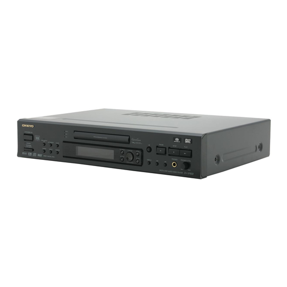
Onkyo DV-SP800 Service Manual
Hide thumbs
Also See for DV-SP800:
- Instruction manual (76 pages) ,
- Brochure & specs (28 pages) ,
- Specification sheet (10 pages)
Table of Contents
Advertisement
Quick Links
Download this manual
See also:
Instruction Manual
QQ
3 7 63 1515 0
Schematic diagram & Printed circuit board view only
TE
L 13942296513
www
.
http://www.xiaoyu163.com
SERVICE MANUAL
SERVICE MANUAL
SACD & DVD AUDIO/VIDEO PLAYER
MODEL
SACD
DVD
STANDBY/ON
CD
VIDEO CIRCUIT
OFF
LAST MEMORY
CLEAR
POWER
ON
DIMMER
REPEAT
RANDOM
Black, Silver and Golden models
BMDD
BMPP/SMPP
BMWT/GMWT
BMWR/GMWR
BMWS/GMWS
BMPS/GMPS
SAFETY-RELATED COMPONENT
WARNING!!
THE MARK
PARTS INDICATES THE CRITICAL FOR RISK OF
FIRE AND ELECTRIC SHOCK.
WHEN REPLACING, BE SURE TO USE PARTS OF
IDENTICAL DESIGNATION.
MAKE LEAKAGE-CURRENT OR RESISTANCE
MEASUREMENTS TO DETERMINE THAT EXPOSED
PARTS ARE ACCEPTABLY INSULATED FROM THE
SUPPLY CIRCUIT BEFORE RETURNING THE
APPLIANCE TO THE CUSTOMER.
x
ao
u163
y
i
http://www.xiaoyu163.com
2 9
8
DV-SP800
120V AC, 60Hz
230-240V AC, 50Hz
Q Q
3
6 7
1 3
1 5
120/220-230V AC,
50/60Hz
230-240V AC, 50/60Hz
FOUND ON SOME COMPONENT
co
.
9 4
2 8
Ref. No. 3742
CH
DISPLAY
AUDIO SEL
TV / VCR
PAUSE
STOP
PLAY
STEP/SLOW
PHONES
PHONES LEVEL
REPEAT
DISPLAY
A-B
MIN
DV-SP800
SACD & DVD AUDIO/VIDEO PLAYER
1
4
7
-- / ---
+ 10
RC-498DV
0 5
8
2 9
9 4
2 8
m
DV-SP800
9 9
102001
ENTER
VOL
VIDEO OFF
DIMMER
MUTING
STEP/SLOW
PAUSE
SPEED
SURROUND
RANDOM PROGRAM CLEAR
PICTURE
COND M
FUNCTION M
2
3
5
6
8
9
ENTER
0
SEARCH
REMOTE CONTROLLER
RC-498DV
9 9
Advertisement
Table of Contents

Related Manuals for Onkyo DV-SP800


Summary of Contents for Onkyo DV-SP800
- Page 1 DV-SP800 3 7 63 1515 0 Ref. No. 3742 102001 SERVICE MANUAL SERVICE MANUAL Schematic diagram & Printed circuit board view only SACD & DVD AUDIO/VIDEO PLAYER DV-SP800 MODEL ENTER VIDEO OFF SACD DISPLAY DIMMER AUDIO SEL MUTING TV / VCR...
-
Page 2: Specifications
DV-SP800 3 7 63 1515 0 SPECIFICATIONS General Power supply USA & Canadian models AC 120 V, 60 Hz European models AC 230 - 240 V, 50 Hz South American models AC 230 240 V, 50 Hz World wide models... -
Page 3: Laser Warning
DV-SP800 3 7 63 1515 0 SERVICE PROCEDURES-1 PROTECTION OF EYES FROM LASER BEAM DURING SERVICING This set employs a laser. Therefore, be sure to follow Laser Diode Properties carefully the instructions below when servicing. WARNING!! Wavelength: 650 nm... - Page 4 DV-SP800 3 7 63 1515 0 SERVICE PROCEDURES-2 INITIALIZING Factory-shipped condition Push button "ON" (Mechanical SW) Press the [STOP] and [STANDBY] same time. (Wait until FL display "No Disc") . Push button "STANDBY". Others Phones level volume -------- MIN.
-
Page 5: Panel View
When STANDBY/ON button is pressed to ON while the POWER DIMMER button switch is set to ON, the DV-SP800 turns on and the STANDBY Toggle to control the lightness of the display (4 steps). indicator turns off. The indicator around button lights up. - Page 6 DV-SP800 3 7 63 1515 0 PANEL VIEW-2 DISPLAY 10 11 DVD - AUDIO SACD V CD LAST TITLE GROUP CHP TRACK REMAIN S RS D.MIX COND TOTAL PROGRESSIVE 13 14 15 16 D indicator COND indicator Lights when Dolby Digital sound is selected and played back. (Only PROGRESSIVE indicator with DVDs recorded in Dolby Digital).
-
Page 7: Rear Panel
DV-SP800 3 7 63 1515 0 PANEL VIEW-3 REAR PANEL COMPONENT S VIDEO VIDEO VIDEO OUTPUT AC INLET CH 1 CH 2 FRONT SURR 1 CENTER SURR 2 SACD & DVD AUDIO/VIDEO PLAYER DV-SP 800 MODEL NO. DIGITAL OUTPUT... - Page 8 http://www.xiaoyu163.com 3 7 63 1515 0 L 13942296513 u163 http://www.xiaoyu163.com...
- Page 9 DV-SP800 3 7 63 1515 0 EXPLODED VIEW (LOADING MECHANISM) / PARTS LIST EXPLODED VIEW (LOADING MECHANISM) / PARTS LIST Z101 : DVD Mechanism DB-VLD301-006 GEM1036 GEM1036 To DVDM CN151 Lubricating Oil GYA1001 L 13942296513 Lubricating Oil Lubricating Oil...
-
Page 10: Parts List
DV-SP800 3 7 63 1515 0 EXPLODED VIEW / PARTS LIST TRAVERSE MECHANISM ASSY 17 (Torque : 0.12+/- 0.01 N m) 4 (Adjustment Screw) 4 (Adjustment Screw) (Torque : 0.12+/- 0.01 N m) L 13942296513 17 (Torque : 0.12+/- 0.01 N m) PARTS LIST Mark No. - Page 11 http://www.xiaoyu163.com 3 7 63 1515 0 L 13942296513 u163 http://www.xiaoyu163.com...
- Page 12 http://www.xiaoyu163.com 3 7 63 1515 0 L 13942296513 u163 http://www.xiaoyu163.com...
- Page 13 http://www.xiaoyu163.com 3 7 63 1515 0 L 13942296513 u163 http://www.xiaoyu163.com...
- Page 14 http://www.xiaoyu163.com 3 7 63 1515 0 L 13942296513 u163 http://www.xiaoyu163.com...
- Page 15 http://www.xiaoyu163.com 3 7 63 1515 0 L 13942296513 u163 http://www.xiaoyu163.com...
- Page 16 DV-SP800 3 7 63 1515 0 PC BOARD NAAR-7616 L . M U T E C 1 1 3 5 R . M U T E 1 2 2 G N D R 1 1 1 3 1 . 8 K...
-
Page 17: Schematic Diagram
http://www.xiaoyu163.com 3 7 63 1515 0 SCHEMATIC DIAGRAM U1: OUTPUT TERMINAL PC Q 1 9 1 2 Q 1 9 0 2 U10: Regulator-2PC NAETC-7775 2 . 4 w 7 9 M 0 5 P Q 3 R D 2 3 1 4 0 m A R 1 9 0 1 0 A12V... - Page 18 DV-SP800 3 7 63 1515 0 U13: HEADPHONE TERMINAL PC BOARD RCUIT PC BOARD NADG-7761 NADG-7761 R 4 7 9 3 3 K Q 4 7 1 N J M 4 5 6 5 R 4 8 1 4 7 0...
- Page 19 http://www.xiaoyu163.com 3 7 63 1515 0 SCHEMATIC DIAGRAM SACD CIRCUIT PC BOARD SECTION U14: SACD CIR 3 . 3 3 . 3 L 1 4 0 3 B L M 2 1 B 2 2 2 I S 4 2 S 1 6 1 0 0 - 7 T C 1 4 2 6 Q 1 4 0 2 R 1 4 8 8...
- Page 20 http://www.xiaoyu163.com 3 7 63 1515 0 L 13942296513 u163 http://www.xiaoyu163.com...
- Page 21 DV-SP800 3 7 63 1515 0 U3: STANDBY LED PC BOARD NADIS-7619 NADIS-7619 7 4 8 R 7 4 9 R 7 5 0 R 7 7 1 R 7 7 2 8 2 0 1 . 8 K 3 .
- Page 22 http://www.xiaoyu163.com 3 7 63 1515 0 SCHEMATIC DIAGRA DISPLAY CIRCUIT PC BOARD SECTION NADIS-7618 Q 7 0 5 P I C - 3 7 0 4 3 T H 2 R 7 4 7 R 7 4 R720 8.2k 3 9 0 4 7 0 R721 5.6k...
- Page 23 http://www.xiaoyu163.com 3 7 63 1515 0 L 13942296513 u163 http://www.xiaoyu163.com...
- Page 24 http://www.xiaoyu163.com 3 7 63 1515 0 L 13942296513 u163 http://www.xiaoyu163.com...
- Page 25 DV-SP800 3 7 63 1515 0 R 2 4 1 4 Q 2 8 5 3 R 2 4 1 7 Q 2 8 5 4 C V D R V R N 2 4 0 3 R N 2 4 0 3...
- Page 26 DV-SP800 3 7 63 1515 0 R 2 4 1 4 Q 2 8 5 3 R 2 4 1 7 C V D R V C V 1 R N 2 4 0 3 R 2 4 1 9...
-
Page 27: Video Section
http://www.xiaoyu163.com 3 7 63 1515 0 SCHEMATIC DIAGRAM OUT_V U11: VIDEO CIRCUIT PC BOARD OUT_YS OUT_C VIDEO SECTION NAVD-7632 EXCEPT <MPP> R 2 5 0 3 OUT_Y/G Q 2 5 0 1 K T A 1 5 0 4 3 . 3 R 2 2 5 2 + 3 . -
Page 28: Schematic Diagram - Video Section
http://www.xiaoyu163.com 3 7 63 1515 0 SCHEMATIC DIAGRAM U11: VIDEO CIRCUIT PC BOARD OUT_V VIDEO SECTION OUT_YS OUT_C NAVD-7632 <MPP> only R 2 5 0 3 OUT_Y/G Q 2 5 0 1 K T A 1 5 0 4 3 . 3 R 2 2 5 2 0 + 3 . - Page 29 http://www.xiaoyu163.com 3 7 63 1515 0 L 13942296513 u163 http://www.xiaoyu163.com...
- Page 30 V / Y _ I N V / Y _ I N C 2 9 3 2 4 7 0 / 6 . 3 1 B _ I N u163 V I D E O _ G N D 7 DV-SP800 8/8 PP2P http://www.xiaoyu163.com...
-
Page 31: Schematic Diagram
http://www.xiaoyu163.com 3 7 63 1515 0 SCHEMATIC DIAGRAM U12: SCART TERMINAL PC BOARD SECTION <MPP> only A _ R C H R C H _ O U T A _ G N D A _ G N D A _ L C H L C H _ O U T A _ R C H A _ L C H... - Page 32 http://www.xiaoyu163.com 3 7 63 1515 0 L 13942296513 u163 http://www.xiaoyu163.com...
- Page 33 DV-SP800 3 7 63 1515 0 : The power supply is shown with the marked box. : AUDIO (DIGITAL) SIGNAL ROUTE L 13942296513 1.8V REGULATOR u163 http://www.xiaoyu163.com...
-
Page 34: Main P.c.board
http://www.xiaoyu163.com 3 7 63 1515 0 SCHEMATIC DIAGRAM MAIN PC BOARD-4 DVD-AUDIO DSP L 13942296513 150/4 u163 http://www.xiaoyu163.com... - Page 35 http://www.xiaoyu163.com 3 7 63 1515 0 L 13942296513 u163 http://www.xiaoyu163.com...
- Page 36 DV-SP800 3 7 63 1515 0 : RF (VIDEO) SIGNAL ROUTE (VD) : VIDEO DATA SIGNAL ROUTE (AD) : AUDIO DATA SIGNAL ROUTE : AUDIO SIGNAL ROUTE : AUDIO (DIGITAL) SIGNAL ROUTE (VD) L 13942296513 (VD) (VD) AV-1 2/4, 4/4 u163 http://www.xiaoyu163.com...
- Page 37 http://www.xiaoyu163.com 3 7 63 1515 0 SCHEMATIC DIAGRAM MAIN PC BOARD-3 2/4, 4/4 64M DRAM C219 220/4 (VD) (VD) (AD) L 13942296513 SCRUT u163 http://www.xiaoyu163.com...
- Page 38 http://www.xiaoyu163.com 3 7 63 1515 0 L 13942296513 u163 http://www.xiaoyu163.com...
- Page 39 DV-SP800 3 7 63 1515 0 : The power supply is shown with the marked box. CN501 CLOCK GENERATOR 2/4, 4/4 (VD) (VD) CN601 3.3 5V CONVERTOR L 13942296513 CN401 5 3.3V CONVERTOR CN602 (AD) CN302 CN801 (AD) (VD)
- Page 40 http://www.xiaoyu163.com SCHEMATIC DIAGRAM MAIN PC BOARD-2 3 7 63 1515 0 PGM FLASH MEMORY VYW1896 L 13942296513 u163 http://www.xiaoyu163.com...
- Page 41 http://www.xiaoyu163.com 3 7 63 1515 0 SCHEMATIC DIAGRAM MAIN PC BOARD-1 (RF) 100/6.3 RF IC L 13942296513 CN101 (RF) CN103 FTS DRIVER CN105 CN601 (F) (F) u163 CN104 http://www.xiaoyu163.com...
-
Page 42: Servo Dsp
DV-SP800 3 7 63 1515 0 (RF) : RF SIGNAL ROUTE : RF (VIDEO) SIGNAL ROUTE : RF (AUDIO) SIGNAL ROUTE (AD) : AUDIO DATA SIGNAL ROUTE : FOCUS SERVO LOOP LINE : TRACKING SERVO LOOP LINE : SLIDER SERVO LOOP LINE... - Page 43 http://www.xiaoyu163.com P2801A 3 7 63 1515 0 P902B P1810 P471B P106A CN401 P903A Q1906 P902A P1701B L 13942296513 P901B CN501 P1701A P1401A u163 http://www.xiaoyu163.com...
- Page 44 DV-SP800 3 7 63 1515 0 PRINTED CIRCUIT BOARD VIEW MAIN CIRCUIT PC BOARD DB-VPB308 SIDE B STEPPING SPINDLE PICKUP MOTOR CN601 MOTOR ASSY (CARRIAGE) L 13942296513 IC251 Q103 IC271 Q109 Q108 Q130 IC903 IC909 IC910 IC608 Q271 Q281...
- Page 45 DV-SP800 3 7 63 1515 0 PRINTED CIRCUIT BOARD VIEW MAIN CIRCUIT PC BOARD DV-VPB308 SIDE A L 13942296513 IC401 IC911 IC912 IC901 Q101 Q118 IC281 Q543 IC351 IC532 IC211 IC261 Q102 Q116 Q107 Q542 Q112 Q571 u163 IC210...
- Page 46 DV-SP800 3 7 63 1515 0 PRINTED CIRCUIT VIEW U2: Display circuit PC board NADIS-7618 From soldering side view L 13942296513 Component side u163 http://www.xiaoyu163.com...
- Page 47 DV-SP800 3 7 63 1515 0 PRINTED CIRCUIT VIEW U2: Display circuit PC board NADIS-7618 From soldering side view R748 R750 R749 R719 R066 R052 R759 R713 R712 R794 R711 R710 R709 R780 R781 R795 R723 R722 R725 R724...
-
Page 48: Printed Circuit Board View
DV-SP800 3 7 63 1515 0 PRINTED CIRCUIT BOARD VIEW U12: SCART TERMINAL PC BOARD <MPP> only : Component side pattern : Soldering side pattern L 13942296513 u163 Component side view http://www.xiaoyu163.com... - Page 49 DV-SP800 3 7 63 1515 0 PRINTED CIRCUIT VIEW U14: SACD CIRCUIT PC BOARD NADG-7761 U13: HEADPHONE TERMINAL PC BOARD NAAF-7617 L 13942296513 Component side view : Component side pattern : Soldering side pattern u163 2513776 2513776 25137 Component side view...
- Page 50 DV-SP800 3 7 63 1515 0 PRINTED CIRCUIT BOARD VIEW From Soldering side view U3: STANDBY LED PC BOARD NADIS-7619 NCDIS-7619 NCDIS-7619 25137619 25137619 Q722 STANDBY S723 VIDEO CIRCUIT DIMMER Component side Soldering side U4: POWER TRANSFORMER PC BOARD...
- Page 51 http://www.xiaoyu163.com 3 7 63 1515 0 L 13942296513 u163 http://www.xiaoyu163.com...
- Page 52 DV-SP800 3 7 63 1515 0 PRINTED CIRCUIT BOARD VIEW From Soldering side view U3: STANDBY LED PC BOARD NADIS-7619 NCDIS-7619 NCDIS-7619 25137619 25137619 Q722 STANDBY S723 VIDEO CIRCUIT DIMMER Component side Soldering side U4: POWER TRANSFORMER PC BOARD...
- Page 53 DV-SP800 3 7 63 1515 0 PRINTED CIRCUIT BOARD VIEW From Sodering side view U9: VOLTAGE SELECTOR PC BOARD NASW-7624 <MWS, MWR, MPS> only LOAB ASSY (DVD MECHANISM) S992 S992 NCSW-7624 25137624 J905B J906B J904A CN103 LOADING U6: POWER SWITCH PC BOARD...
- Page 54 DV-SP800 3 7 63 1515 0 PRINTED CIRCUIT BOARD VIEW U11: VIDEO CIRCUIT PC BOARD : Component side pattern : Soldering side pattern NAVD-7632 L 13942296513 u163 Component side view http://www.xiaoyu163.com...
- Page 55 DV-SP800 3 7 63 1515 0 FL TUBE VIEW Pin connection DVD-AUDIO DVD-AUDIO SACD V CD SACD V CD PBCRANDOM RANDOMMEMORY MEMORY 1A-B 1A-B LFE LAST D.MIX COND. PRO LOGIC PRO LOGIC TITLE TITLE GROUP GROUP COND. CHP TRACK...
- Page 56 DV-SP800 3 7 63 1515 0 Disassembly of the Traverse Mechanism Assy-1 Remove the top cover and Tray Panel. Remove the Loading Mechanism Assy (Screws 4). Remove the Tray panel and Front Panel. Remove a screw. Remove the Bridge (Screw 1).
- Page 57 DV-SP800 3 7 63 1515 0 Disassembly of the Traverse Mechanism Assy-2 When Removing The Pickup Assy Remove two screws. Remove the Pickup Flexible Cable. Cautions: Screw is locked with Screw Lock. Please lock it with Screw Lock when installs it.
- Page 58 DV-SP800 3 7 63 1515 0 Disassembly of the Traverse Mechanism Assy-3 Styling the Pickup Flexible Cable Fold a edge of lining part of the Pickup Flexible Cable. Insert the Pickup Flexible Cable in connector, and lock it surely.
-
Page 59: Adjustment Procedures
DV-SP800 3 7 63 1515 0 ADJUSTMENT PROCEDURES-1 ADJUSTMENT OF DVD MECHANISM-1 1. Adjustment items and location Tangential and Radial Height Coarse Adjustment Tangential Radial adjustment adjustment DVD Jitter Adjustment screw screw How to initialize the Focus Sweep Setting [Electrical Part] Electrical adjustments are not required. - Page 60 DV-SP800 3 7 63 1515 0 ADJUSTMENT PROCEDURES-2 ADJUSTMENT OF DVD MECHANISM-2 A. Connection VIDEO OUT VIDEO IN B. Test mode SETTING THE REMOTE CONTROLER Press 1 as holding down DVD. Remote controller C: TEST MODE: ON RC-484M Part No. 24140484 STANDBY switch is ON.
- Page 61 DV-SP800 3 7 63 1515 0 ADJUSTMENT PROCEDURES-3 ADJUSTMENT OF DVD MECHANISM-3 TEST MODE: PLAY An address is displayed < When playback with the target address of disc (DVD)> For example, when playback with # 30000 During PLAY Press keys in order...
- Page 62 DV-SP800 3 7 63 1515 0 ADJUSTMENT PROCEDURES-4 ADJUSTMENT OF DVD MECHANISM-4 DVD Jitter Adjustment Playback method of inner and outer address for the purpose is refererd to "5. TEST MODE". Use disc: GGV1025 Test mode Play the DVD test disc at outer track...
- Page 63 DV-SP800 3 7 63 1515 0 ADJUSTMENT PROCEDURES-5 ADJUSTMENT OF DVD MECHANISM-5 Initialize the Focus Sweep Setting Purpose: To set the sweep which was correct with the individual Traverse mechanism. RC-484M CLEAR Monitor Memory Clear!!! PL Region : X1 ROM Version : 1.128...
- Page 64 DV-SP800 3 7 63 1515 0 ADJUSTMENT PROCEDURES-6 CHECKING THE ERROR RATE Setting remote controller Press the hold down DVD button, then press 1 button. Check the CD error rate CD test disc Waiting for 8 seconds Play [Example] CD error rate = 33 / (7.35 x 5 x 1000) = 0.9 x 10...
-
Page 65: Upgrade Firmware
DV-SP800 3 7 63 1515 0 UPGRADE FIRMWARE-1 Prepares for upgrade firmware ID DATA DISC (DB-VPB302) REMOTE CONTROLLER for UPGRADE Part No. 0R117 Part No. 24140484 (RC-484M) It is remote control of the exclusive use for inputting ID data and upgrade It is used for the input of ID data. - Page 66 DV-SP800 3 7 63 1515 0 UPGRADE FIRMWARE-2 Connections Rear panel view COMPONENT S VIDEO VIDEO VIDEO OUTPUT AC INLET CH 1 CH 2 FRONT SURR 1 CENTER SURR 2 SACD & DVD AUDIO/VIDEO PLAYER DV-SP 800 MODEL NO.
- Page 67 DV-SP800 3 7 63 1515 0 UPGRADE FIRMWARE-3 Flow chart In the case of upgrade firmware In the case of replace of the DVD main board Replace of the DVD main board Check the firmware Setting the regional code...
- Page 68 DV-SP800 3 7 63 1515 0 UPGRADE FIRMWARE-4 Check the firmware Please operate it by remote controller (RC-484M). 1. Press the DVD button. 2. Press SETUP button. 3. Operate cursor button and select General menu. Refer to 4. Operate cursor button and select Setup Menu mode.
- Page 69 DV-SP800 3 7 63 1515 0 UPGRADE FIRMWARE-5 Download firmware 1. Start MS-DOS prompt using the start-up menu of PC. Windows of MS DOS prompt Example C: WINDOWS>_ L 13942296513 2. Press the Enter button, after input cd.. by the keyboard.
- Page 70 DV-SP800 3 7 63 1515 0 UPGRADE FIRMWARE-6 Download procedures 5. Connect the PC and set. 6. NO DISC. codition. 7. Turn ON the power supply switch of the unit. 8. Press the Enter key of PC. 9. Press the Enter button, after input MO by the keyboard.
- Page 71 http://www.xiaoyu163.com DD-SP800 3 7 63 1515 0 UPGRADE FIRMWARE-7 Download procedures Completed download view The state which download completed Download was completed. L 13942296513 u163 http://www.xiaoyu163.com...
- Page 72 MDD1N MPP2P L 13942296513 UPT3P UDT3P UGK3P UPA4P UDS4P UGR6P FL display NO DISC 3. Turn OFF power of DV-SP800. 4. Disconnect DV-SP800 and PC. Confirm the firmware and regional cord Refer to about check procedure. (Page 4) u163 http://www.xiaoyu163.com...
- Page 73 DV-SP800 3 7 63 1515 0 UPGRADE FIRMWARE-9 Setting the ID number. 1. Input the ID number recorded before using the number button. (Refer to " Check ID number" TV Monitor [Player's ID Number Setting] ID Number? > 0 0 0 0 0 0 0 0 1 Number key <PLAY>...
- Page 74 DV-SP800 3 7 63 1515 0 UPGRADE FIRMWARE-10 Confirm the ID number For use the RC-484M remote controller RC-484M 1. Power ON and standby ON of the unit. Part No. 24140484 2. Press RETURN key. 3. Press STEREO key before displayed TV monitor.
-
Page 75: Error Code
DV-SP800 3 7 63 1515 0 ERROR CODE ERROR CODE Error codes that are displayed on the FL display. FL Display Possible causes Operation of the unit The sound may not out AV1 VER AV-1 chip is not a match with the program of system controller with the specific audio. -
Page 76: Troubleshooting
DV-SP800 3 7 63 1515 0 TROUBLE SHOOTING Condition When No Power ON FL is not turned ON FL indication is unusual START Power ON Blow out thermistor or fuse on the POWER TRANSFORMER PC BOARD. (Check the each voltage.) FL controller IC (Q70I) on the DISPLAY CIRCUIT PC BOARD is damaged. -
Page 77: Packing View
DV-SP800 3 7 63 1515 0 PACKING VIEW A952, A065 A953,A954 Tape A901 A530 <MDD> only A903 A951 A833 <MPP> only A905 RC-498DV A906 A051 A982 <MWT, A902 MWS> P981 A057 A907 <MPP> only L 13942296513 Front side A051... - Page 78 EXPLODED VIEW PARTS LIST http://www.xiaoyu163.com B : Black color S : Silver color G : Golden color 3 7 63 1515 0 <MDD1N> : U.S.A. and Canadian area, Regional code: 1, TV system: NTSC <MPP2P> : European area, Regional code: 2, TV system: PAL <MWT3P>: South East Asia and Middle East area, Regional code: 3, TV system: PAL <MPS4P>: Australian area, Regional code: 4, TV system: PAL <MWS4P>: South America area, Regional code: 4, TV system: PAL...
- Page 79 SCREW 3TTB+8B(BC), B 838430088 http://www.xiaoyu163.com SCREW 3TTB+8B(UN), S, G 838930088 A401 F PANEL 27212429 B <MDD1N> A401 F PANEL B <MPP2P>, B <MPS4P>, 27212432 3 7 63 1515 0 B <MWT3P>, B <MWS4P> A401 F PANEL S <MPP2P> 27212430 A401 F PANEL G <MWT3P>, 27212431...
- Page 80 Inlet terminal PC board assy NAPS-7621-1F <MWR6P> 1H490521-1F http://www.xiaoyu163.com Power switch PC board assy NASW-7622-1A <MDD1N> 1H490522-1A Power switch PC board assy NASW-7622-1B <MPP2P> 1H490522-1B Power switch PC board assy NASW-7622-1C <MWT3P> 1H490522-1C 3 7 63 1515 0 Power switch PC board assy NASW-7622-1D <MPS4P>...
- Page 81 EAN LABEL 29363197 S <MPP> A417 EAN LABEL G <MWT>,G <MPS>,G <MWR> 29363198 A419 LABEL LABEL SHEET <MDD> 29360840 A530 WRNTY CARD 29365090A (ONKYO) <MDD> A833 POLY BAG 350*250 29100097-1A A901 PIN CORD AS RCA3P(YWR) 2010379 A902 BATTERY UM-3 3010054 A903 PLUG CORD 3.5-MINI PLUG (RI)
- Page 82 PRINTED CIRCUIT BOARD PARTS LIST http://www.xiaoyu163.com <MDD1N> : U.S.A. and Canadian area, Regional code: 1, TV system: NTSC <MPP2P> : European area, Regional code: 2, TV system: PAL 3 7 63 1515 0 <MWT3P>: South East Asia and Middle East area, Regional code: 3, TV system: PAL <MPS4P>: Australian area, Regional code: 4, TV system: PAL <MWS4P>: South America area, Regional code: 4, TV system: PAL <MWR6P>: Chinese, Regional code: 6, TV system: PAL...
- Page 83 C1213 TF C ECQ-B50V-101K 374721015 http://www.xiaoyu163.com C1214 TF C ECQ-B50V-101K 374721015 C1215 VX C CE04W16V-470M(VX) 393344717 C1216 VX C CE04W16V-470M(VX) 393344717 3 7 63 1515 0 C1221 TF C ECQ-B50V-681J 374726814 C1222 TF C ECQ-B50V-681J 374726814 C1223 TF C ECQ-B50V-152J 374721524 C1224 TF C...
- Page 84 C1924 ELECT C CE04W6.3V-100M 354721019 http://www.xiaoyu163.com C1925 ELECT C CE04W6.3V-1000M 354721029 C1926 ELECT C CE04W50V-4.7M 354780479 C1927 ELECT C CE04W16V-10M(VZ) 394541007 3 7 63 1515 0 C1929 ELECT C CE04W6.3V-470M(VZ) 394524717 C1931 ELECT C CE04W16V-47M 354744709 C1934 ELECT C CE04W6.3V-220M(VZ) 394522217 CN401 SOCKET...
- Page 85 Q1102 CS4392-KS 22241635R2 http://www.xiaoyu163.com Q1103 NJM2068V 22241869R2 Q1104 NJM2068V 22241869R2 Q1105 NJM4565V 22241554R2 3 7 63 1515 0 Q1106 NJM4565V 22241554R2 Q1109 2SD655-E 2211705 Q1109 or 2SD655-F 2211706 Q1110 2SD655-E 2211705 Q1110 or 2SD655-F 2211706 Q1111 2SD655-E 2211705 Q1111 or 2SD655-F 2211706 Q1112...
- Page 86 Q1134 or 2SC2712-Y 2213144R2 http://www.xiaoyu163.com Q1134 or 2SC2712-GR 2213145R2 Q1201 IC(REGURATOR) 74VHC157FT 22274157ER2 Q1202 CS4392-KS 22241635R2 3 7 63 1515 0 Q1203 NJM2068V 22241869R2 Q1204 NJM2068V 22241869R2 Q1205 NJM4565V 22241554R2 Q1206 NJM4565V 22241554R2 Q1209 HN1C03F-B 2216141R2 Q1210 HN1C03F-B 2216141R2 Q1211 HN1C03F-B 2216141R2 Q1212...
- Page 87 Q1703 PHT CP GP1FA551TZ 24120085 http://www.xiaoyu163.com Q1901 IC (REGULATOR) 7812 222780124 Q1901A HEAT SINK RAD-178 27160518 Q1901B SCREW 3P+10FN(BC) 82143010 3 7 63 1515 0 Q1903 IC (REGULATOR) 78M12HF 222780125 Q1903A RADIATOR RAD-51(B) 27160220 Q1903B SCREW 3P+10FN(BC) 82143010 Q1904 IC (REGULATOR) 79M12HF 222790125 Q1904A...
- Page 88 D708 SEL2E10C 225374 http://www.xiaoyu163.com D711 ZENER D UDZS4.7B 224550470R2 E703 FUSE LABEL T2.5A 250V_F911,F912 29363314 E703 FUSE LABEL T2.5A 250V_F911,F912 29363314 3 7 63 1515 0 E703 FUSE LABEL T2.5A 250V_F911,F912 29363314 E703 FUSE LABEL T2.5A 250V_F911,F912 29363314 E704 FUSE LABEL T800mAL250V 29362519 E704...
- Page 89 Q721 KRC107S 2216340R2 http://www.xiaoyu163.com Q721 or RN1407 2216260R2 Q722 KRC107S 2216340R2 Q722 or RN1407 2216260R2 3 7 63 1515 0 S721 PUSH SW NPS-111-S662 25035699 S722 PUSH SW NPS-111-S662 25035699 S723 PUSH SW NPS-111-S662 25035699 U4: POWER TRANSFORMER PC BOARD (NAPS-7620) DESTINA- CIRCUIT NO.
- Page 90 S991 or P SW NPS-111-L512P 25035550 http://www.xiaoyu163.com U8: REGULATOR_1 PC BOARD (NAETC-7774) DESTINA- 3 7 63 1515 0 CIRCUIT NO. PART NAME DESCRIPTION PART NO. REMARK TION C1919 ELECT C CE04W6.3V-220M 355722219 C1936 ELECT C CE04W35V-10M(S) 353761009 P1904 JUMPER LEAD JL3 250 H 3J250606H P1904A...
- Page 91 P2402 SOCKET NSCT-8P1743 25051956 http://www.xiaoyu163.com P2501 PIN JACK NPJ-3PDGLR429 25045622 MPP2P P2801A SOCKET NSCT-20P2483 25052586R2 MPP2P P2801B SOCKET NSCT-20P2483 25052586R2 3 7 63 1515 0 MPP2P P2903 SOCKET NSCT-21P2557 25052660 MPP2P P2904 SOCKET NSCT-21P2557 25052660 MPP2P P902B PLUG NPLG-10P138 25055154 Except P903B PLUG...
- Page 92 Q2602 or KTC3875-Y 2216174R2 http://www.xiaoyu163.com Q2602 or 2SC2712-Y 2213144R2 Q2603 MAX4016ESA 22241441R2 MPP2P Q2651 KTA1504-GR 2216185R2 3 7 63 1515 0 MPP2P Q2651 or 2SA1162-GR 2214375R2 MPP2P Q2651 or KTA1504-Y 2216184R2 MPP2P Q2651 or 2SA1162-Y 2214374R2 MPP2P Q2701 KTA1504-GR 2216185R2 MPP2P Q2701 or 2SA1162-GR...
- Page 93 Q2905 or KTC3875-Y 2216174R2 http://www.xiaoyu163.com Q2906 2SC2712-GR 2213145R2 Q2906 or KTC3875-GR 2216175R2 Q2906 or 2SC2712-Y 2213144R2 3 7 63 1515 0 Q2906 or KTC3875-Y 2216174R2 Q2907 4053BF(TC4053BF) 222840531R2O Q2908 4053BF(TC4053BF) 222840531R2O Q2909 2SC2712-GR 2213145R2 Q2909 or KTC3875-GR 2216175R2 Q2909 or 2SC2712-Y 2213144R2 Q2909 or...
- Page 94 L1405 CHOKE COIL BLM21B222SPT 230921R2 http://www.xiaoyu163.com L1406 CHOKE COIL BLM21B222SPT 230921R2 L1407 CHOKE COIL BLM21B222SPT 230921R2 L1408 EMIFIL BK1608LL241-T 230959R1 3 7 63 1515 0 L1409 EMIFIL BK1608LL241-T 230959R1 L1410 EMIFIL BK1608LL241-T 230959R1 P1401B SOCKET NSCT-20P2200 25052303 Q1401 CXD2753R 22241829R3 Q1402 IS42S16100-7T 22241686R2...
- Page 95 Sales & Product Planning Div. : 2-1, Nisshin-cho, Neyagawa-shi, OSAKA 572-8540, JAPAN Tel: 072-831-8111 Fax: 072-833-5222 ONKYO U.S.A. CORPORATION 18 Park Way, Upper Saddle River, N.J. 07458, U.S.A. Tel: 201-785-2600 Fax: 201-785-2650 E-mail: onkyo@onkyousa.com ONKYO EUROPE ELECTRONICS GmbH Industriestrasse 20, 82110 Germering, GERMANY Tel: 089-849-320 Fax: 089-849-3265 E-mail: info@onkyo.de...
Need help?
Do you have a question about the DV-SP800 and is the answer not in the manual?
Questions and answers