Table of Contents
Advertisement
Advertisement
Table of Contents

Subscribe to Our Youtube Channel
Related Manuals for FLIR SC5000


Summary of Contents for FLIR SC5000
- Page 1 DCOO2U-L SC5000 User Manual Advanced Thermal Solutions SC5000 User Manual...
- Page 2 Advanced Thermal Solutions SC5000 User Manual PAGE LEFT INTENTIONNALY BLANK DCOO2U-L SC5000 User Manual Page 2...
-
Page 3: Table Of Contents
Diagnostics ..................18 9.1. Diagnostic table .................... 18 9.1. How to contact after sale service? ..............21 10. Technical data ..................23 10.1. Characteristics ....................23 10.2. Mechanical interface ..................25 10.3. Electrical interface ..................26 DCOO2U-L SC5000 User Manual Page 3... -
Page 4: For Your Safety
SC5000 User Manual 2. For your safety To ensure no damage to your FLIR Systems equipment, you or other people, carefully read the following recommendations before using your equipment. Then keep these instructions in a place easily accessible to all those which will... -
Page 5: Precautions
Advanced Thermal Solutions SC5000 User Manual 3. Precautions To maximize the lifetime and get the best use of your FLIR Systems equipment, observe the following instructions when storing or using it. Keep it dry Avoid abrupt changes This device will be damaged if... -
Page 6: General Overview
SC5000 User Manual 4. General Overview 4.1. Product Overview The SC5000 camera is especially designed for the most demanding users of infrared technology, carrying out thermal and radiometric measurements with the greatest sensitivity, precision and speed. The detector with the format 320x256 offers the greatest sensitivity, while keeping an extraordinary dynamic range as well as a perfect linearity. - Page 7 1 Camera Characterization file Optional : 1 4 slot filter wheel (Optional) 1 Camera LINK Frame Grabber (Optional) 1 Computer for camera command and image acquisition. (Optional) 1 or more additional lenses (Optional) 1 Tripod (Optional) DCOO2U-L SC5000 User Manual Page 7...
-
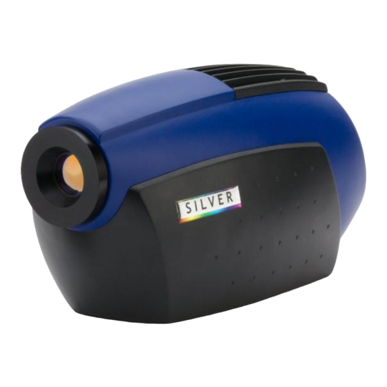
Page 8: Camera Description
Motorized 27mm integrated lens Camera LINK connector (Optional) ON/OFF button Lockin connector (Optional) Vidéo output External Trigger Power supply connector USB or GigE connector Thread for fixing on a plate Tripod Thread Filter Wheel (Optional) DCOO2U-L SC5000 User Manual Page 8... -
Page 9: Starting With The Camera
The camera is turned on by pressing the ON/OFF button for 2 seconds. The camera will then start automatically. After a few seconds, 10s typically, the system displays a pattern on the video output. Figure 1 : Pattern DCOO2U-L SC5000 User Manual Page 9... -
Page 10: Pointing And Focusing
Before taking a measurement, ensure that the object is located at the center of the image and that focusing is optimized. SC5000 Cameras have an integrated motorized lens, and focusing is carried out by using the control buttons in the software. - Page 11 Advanced Thermal Solutions SC5000 User Manual FLIR Systems offers training schemes allowing you to use this equipment to its full potential. You can contact FLIR Systems in order to establish your training requirements. DCOO2U-L SC5000 User Manual Page 11...
-
Page 12: Using Your Camera
Place the locating pin of mounting opposite to the corresponding hole in lens. A white dot indicates the position. Gently insert the lens and turn the ring clockwise. DCOO2U-L SC5000 User Manual Page 12... -
Page 13: Change Of Filter Wheel
Store immediately the wheel in its case. Take care not to touch the filters. Replace the cap or another wheel proceeding the opposite way. It is important not to leave the camera without cap or wheel so that dust cannot enter the camera. DCOO2U-L SC5000 User Manual Page 13... -
Page 14: Lockin Connection (Optional)
Advanced Thermal Solutions SC5000 User Manual Lockin connection 6.3. (Optional) To use the lockin option, you need an X0502 cable linked to the SC5000 lockin connector. Lockin Input Range 10V peak to peak (AC only). Rand 1 Input Range -5/+5V (AC + DC). -
Page 15: Irig-B Time Stamping (Optional)
Most IRIG-B generators deliver a signal called “1PPS” for “1 Pulse Per Second”. This signal is synchronized to the beginning of each frame. To use the IRIG-B option, you need an X0904 cable linked to the SC5000 lockin connector. Please note that Rand2 isn’t available with the IRIG-B option. -
Page 16: Maintenance
Put the camera in its case and store it in a dry cool place, away from dust. Do not expose the case and its contents to temperatures lower than -40°C (-40°F) or higher than 70°C (158 °F). DCOO2U-L SC5000 User Manual Page 16... -
Page 17: Accessories
8.1. Additional lenses FLIR Systems offers a range of additional radiometric lenses for the SC5000 camera. These lenses are accompanied by a data sheet. They are assembled in addition to the lens integrated into the camera. -
Page 18: Diagnostics
Advanced Thermal Solutions SC5000 User Manual 9. Diagnostics If your camera does not function exactly as it should, check the following table before consulting FLIR Systems after-sales service or your FLIR Systems representative. 9.1. Diagnostic table Problem Action Surface treatment... - Page 19 AGC parameters (Withdraw all the limitations in gain, offset and ROI). Does video monitor remain black? No The problem is solved. Yes Contact FLIR Systems After Sales Service No Live image on Altair Is the camera correctly connected and powered? No remake connections Yes Does...
- Page 20 No Be careful that your measurement will not be coherent. Yes Contact FLIR Systems After Sales Service Defect image Bad quality of NUC or search criteria of Bad (mosaic) in corners pixels too severe. Remake NUC and BPR.
-
Page 21: How To Contact After Sale Service
Advanced Thermal Solutions SC5000 User Manual 9.1. How to contact after sale service? A knowledge base and FAQ are available on the flir’s customer support website: http://flir.custhelp.com Before contacting the after sales service or your representative, note the serial number located on the camera. A FLIR Systems engineer will discuss the procedure with you. - Page 22 10 Business Park Drive, Notting Hill VIC 3168 Email: service@flir.com.au AUSTRALIA FLIR ATS - FRANCE Full Service including calibration Address 19 Boulevard Bidault, Croissy Beaubourg, F77183 Phone: +33 (0)1 60 37 01 00 FRANCE DCOO2U-L SC5000 User Manual Page 22...
-
Page 23: Technical Data
PAL (50 Hz) or NTSC (60 Hz) Remote Control GigE / Camera LINK Overall dim, (mm) 310 x 141 x 159 Weight (W/O lens) 3.8 kg Water & humidity IP54 Operational temperature -20°C +55°C range DCOO2U-L SC5000 User Manual Page 23... - Page 24 PAL (50 Hz) or NTSC (60 Hz) Remote Control USB 2.0 GigE / Camera LINK Overall dim, (mm) 310 x 141 x 159 Weight (W/O lens) 3.8 kg Water & humidity IP54 Operational temperature -20°C +55°C range DCOO2U-L SC5000 User Manual Page 24...
-
Page 25: Mechanical Interface
Advanced Thermal Solutions SC5000 User Manual 10.2. Mechanical interface ² DCOO2U-L SC5000 User Manual Page 25... -
Page 26: Electrical Interface
10.3.1. VIDEO connector Connector reference: LEMO ERP1S306CLN Mating part: LEMO FFA1S306CLAC42Z Signal Characteristic: 75 Ohms Signal Pin# Composite_Video SVideo_Chroma SVideo_Lumi 10.3.2. Power supply connector Connector reference: LEMO ECP1S302CLN Mating part: LEMO FFA1S302CLAC52 Signal Pin# +12V DCOO2U-L SC5000 User Manual Page 26... - Page 27 With IRIG-B Without IRIG-B Signal characteristic characteristic Lockin Lockin 0/+10V AC only 0/+10V AC only IRIG-B Rand 1 Rand 1 -5/+5V DC + AC -5/+5V DC + AC Rand 2 -5/+5V DC + AC 3Vpp DCOO2U-L SC5000 User Manual Page 27...
- Page 28 10.3.5. Camera LINK connector Connector reference: 3M MDR26 Mating cable: Signal Pin# Signal Pin# Inner Shield Inner Shield Xclk- Xclk+ SerTC+ SerTC- SerTFG- SerTFG+ CC1- CC1+ CC2- CC2+ CC3- CC3+ CC4- CC4+ Inner shield Inner shield DCOO2U-L SC5000 User Manual Page 28...
Need help?
Do you have a question about the SC5000 and is the answer not in the manual?
Questions and answers