Powermatic 15S Owner's Manual
Hide thumbs
Also See for 15S:
- Operating instructions and parts manual (40 pages) ,
- Operating instructions and parts manual (120 pages)
Table of Contents

Subscribe to Our Youtube Channel
Related Manuals for Powermatic 15S


Summary of Contents for Powermatic 15S
- Page 1 OWNER’S MANUAL Model 15S Planer WMH TOOL GROUP Consumer Woodworking Division 2420 Vantage Drive Elgin, IL 60123 Ph: 888-804-7129 Fax: 800-274-6840 ▪ E-mail: powermatic@wmhtoolgroup.com M-0460286 10/03 Copyright © WMH Tool Group www.wmhtoolgroup.com...
- Page 2 This manual has been prepared for the owner and operators of a Powermatic Model 15S Planer. Its purpose, aside from proper machine operation, is to promote safety through the use of accepted correct operating and maintenance procedures. Completely read the safety and maintenance instructions before operating or servicing the machine.
-
Page 3: Table Of Contents
TABLE OF CONTENTS Safety Rules............................4-5 Safety Decals ............................6 Features ..............................7 Specifications ............................8 Receiving ..............................9 Installation & Assembly..........................10 Handwheel ............................10 Starter Box ............................11 Extension Tables..........................11 Dust Hood ............................11 Electrical Connections........................12 Extension Cords ..........................12 Adjustments.............................13 Belt Tension ............................13 Pulley Alignment ..........................13 Table Rollers.............................14 Cutterhead ............................15... -
Page 4: Safety Rules
Make certain the work area is well lighted and that a proper exhaust system is used to minimize dust. Powermatic recommends the use of anti-skid floor strips on the floor area where the operator normally stands and that each machine’s work area be marked off. Provide adequate work space around the machine. - Page 5 Misuse. Do not use this Powermatic planer for other than its intended use. If used for other purposes, Powermatic disclaims any real or implied warranty and holds itself harmless for any injury or damage which may result from that use.
-
Page 6: Safety Decals
SAFETY Familiarize yourself with the location and content of these decals on your machine. 6. Disconnect machine from power source before making any 1. Read instruction manual before operating machine. adjustments or cleaning chips away from machine. 2. Do not operate without all guards properly installed. 7. -
Page 7: Features
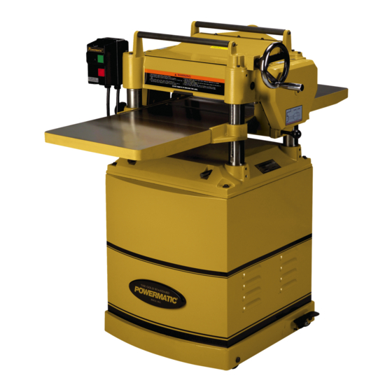
FEATURES: 15S Planer Fig. 2... -
Page 8: Specifications
Net weight (lbs) ........................507 Gross weight (lbs) ......................573 NOTE: The above specifications were current at the time this manual was published, but because of our policy of continuous improvement, Powermatic reserves the right to change specifications without notice and without incurring obligations. -
Page 9: Receiving
RECEIVING Open shipping crate and check for shipping damage. Report any damage immediately to your distributor and shipping agent. Before operating the planer, read the owner’s manual thoroughly assembly, maintenance safety instructions. Contents of crate (Fig. 3): 1 planer 1 dust hood 2 cast iron extension tables 1 handwheel 1 handle... -
Page 10: Installation & Assembly
INSTALLATION & ASSEMBLY Tools required forklift or hoist with slings 8/10, 12/14mmopen-end wrenches (provided) 4 and 5mm hex wrenches (provided) 16mm open-end wrench Remove the screws holding the planer to the pallet and use a forklift or hoist to lift the planer off the pallet. -
Page 11: Starter Box
STARTER BOX Mount the controls as shown in Fig. 8, with the two socket head cap screws which you’ll find mounted to the head casting. Use a 5mm hex wrench. EXTENSION TABLES Mount a cast iron table to the edge of the main table with three M8 x 25 hex cap screws (Fig. -
Page 12: Electrical Connections
A power plug is not provided with the 15S planer. You may either connect a 230 volt plug or "hard- wire" the machine directly to your electrical panel provided there is a disconnect near the machine. -
Page 13: Adjustments
ADJUSTMENTS Tools required 3, 5 and 6mm hex wrenches 10, 12 and 17mm open-end wrenches 0.2” (0.5mm) feeler gauge straight edge gauge block cross-point screwdriver WARNING: Disconnect machine from power source before making any adjustments (except feed rate). BELT TENSION Inspect the tension of the belts frequently during the first few times you use the planer. -
Page 14: Table Rollers
TABLE ROLLERS Your planer is supplied with two table rollers (Fig. 14) which turn as the stock is fed into the machine, thus reducing friction. It is not possible to give exact dimensions on the proper height setting of the table rollers because each type of wood behaves differently. -
Page 15: Cutterhead
There is a certain procedure to follow which will ensure a proper setting of knives on the 15S Planer. Proceed as follows: Disconnect machine from power source. Remove the dust hood and the top cover. -
Page 16: Work Table Parallel To Cutterhead
Put the second gib (gib #2, Fig. 19) in place and insert a screw into gib #2 in the location shown in Fig. 19. Use the adjustment tool to hold the knife in place while making the screw snug. Do not fully tighten screws yet. Return to gib #1 and insert screws into the first two holes. -
Page 17: Know The Transmitting Rollers Of Your Planer
Move the gauge block to the opposite end of the work table. NOTE: Distance from the work table to edge of head casting should be the same. Adjust opposite end in the same manner. If the work table is not parallel to the cutterhead, perform the adjustment procedure as follows: Disconnect machine from power source. -
Page 18: Infeed & Outfeed Roller Spring Tension
INFEED & OUTFEED ROLLER SPRING TENSION The infeed roller (B, Fig. 22) and outfeed roller (E, Fig. 22) are those parts of your planer that feed the stock while it is being planed. The infeed roller and the outfeed roller are under spring tension and this tension must be sufficient to feed the stock uniformly through the planer without slipping but should not be so tight that it causes... -
Page 19: Outfeed Roller Height
NOTE: This procedure uses a home-made gauge block and feeler gauges, which should be sufficient for most planer operations. If extra precise measurements are desired, however, use a dial indicator device. A bed and feed roller gauge with dial indicator (stock # 2230002) is available as an accessory for this machine, and may be purchased through our customer service department. -
Page 20: Chip Deflector
Remove top cover. Loosen the lock nuts (A, Fig. 27) at both ends of the chipbreaker, and turn the set screws to raise or lower the chipbreaker as needed. The set screws should be turned the same amount. When the chipbreaker contacts the gauge block, tighten both lock nuts (A, Fig. -
Page 21: Stock Return Rollers
(Fig. 32), with a cutting range from 0 to 6" (152.4mm). A manual scale is mounted directly to the front column. The model 15S planer also features a digital scale for easier, more precise depth readings. The distance of upward or downward movement is controlled by the handwheel (Fig. -
Page 22: Maintenance
The table should be kept clean and free of rust. MAINTENANCE Some users prefer a paste wax on exposed steel and cast iron surfaces. The wax provides a layer of WARNING: Disconnect machine from protection as well as reducing friction between power source before performing any lumber and the table, making cuts faster and maintenance. -
Page 23: Gearbox Lubricant
GEARBOX LUBRICANT The lubricant in the gear box must be drained and replaced every 2,500 hours. Multi-purpose gear box lubricant will be suitable. To replace the lubricant: Remove the drain plug (A, Fig. 34) with a 14mm wrench. Drain dirty oil thoroughly. Insert and tighten the drain plug (A, Fig. -
Page 24: Functions Of The Digital Scale
Functions of the Digital Scale Figure 39 identifies the parts of the digital scale. The button functions are discussed below, followed by a section giving practical examples of how to calibrate your settings, and how these functions can be used for daily planer operations. Before using the device, wipe down the vertical scale with a dry, soft cloth. -
Page 25: Calibrating & Using Digital Scale
The scale assembly has been mounted and gauge block, should now be input into the aligned with the 15S Planer table at the factory. digital display. Refer to the instructions above The scale should be in vertical position, and the involving the “SET”... - Page 26 relative measurement mode. You can now plane your board with exact results. Of course, you can now toggle back and forth between relative and absolute mode (by pressing ABS button) and get both stock thickness and depth of cut readings at the same time. Clearing a Jammed Board If you have to temporarily move the planer table (for example, to clear a jammed board) use the...
-
Page 27: Optional Accessories
OPTIONAL ACCESSORIES for Model 15S Planer 708816 ..Knives (set of 3) 2230002 ..Bed and feed roller gauge ......Battery for digital scale ......Battery cover TROUBLE-SHOOTING: Digital Scale PROBLEM POSSIBLE CAUSE SOLUTION Flashing digits. 1. Low voltage. 1. Replace battery. -
Page 28: Trouble-Shooting: Performance Problems
TROUBLE-SHOOTING: Performance Problems (15S Planer) PROBLEM POSSIBLE CAUSE SOLUTION Snipe. 1. Table rollers not set properly. 1. Adjust rollers to proper height. 2. Inadequate support of long boards. 2. Support long boards with (NOTE: Snipe can be extension rollers. minimized but not 3. -
Page 29: Trouble-Shooting:mechanical & Electrical Problems
TROUBLE-SHOOTING: Mechanical & Electrical Problems (15S Planer) PROBLEM POSSIBLE CAUSE SOLUTION Uneven depth of cut 1. Knife projection. 1. Adjust knife projection. side to side. 2. Cutterhead not level with bed. 2. Level bed. Board thickness 1. Depth of cut scale incorrect. - Page 30 Machine will not start/ 6. Motor starter failure. 6. (continued) restart or repeatedly If you have access to a voltmeter, you trips circuit breaker can separate a starter failure from a or blows fuses. motor failure by first, verifying incoming voltage at 220+/-20 and second, checking the voltage between starter and motor at 220+/-20.
-
Page 31: Replacement Parts & Service
Replacement Parts & Service Replacement parts are listed on the following pages. To order parts or reach our service department, call our toll-free number between 8:00 a.m. and 4:30 p.m. (CST), Monday through Friday. Having the Model Number and Serial Number of your machine available when you call will allow us to serve you quickly and accurately. Phone No. -
Page 32: Base Assembly
PARTS LIST: Base Assembly (15S Planer) Index Part Description Size Qty. 1 ... 6284703....Base ....................1 2 ... TS-1525021 ....Socket Set Screw ........... M10×12 ....... 8 3 ... 6284705....Crank Case Column................3 4 ... 6284706....Column....................1 5 ... -
Page 33: Base Assembly
Base Assembly (15S Planer) -
Page 34: Table Assembly
7 ..6284738 .......Threaded Shaft ................. 2 8 ..6284736 .......Lock Bushing ..................2 9 ..6284739 .......Knob ............. M12-1.75P ....2 10 ..15S-310......Cast Iron Table Extension ..............2 11 ..15S-311......Screw............M3-0.6P×6L....2 12 ..15S-312......Screw............M5-0.8P×8L....2 13 .. -
Page 35: Table Assembly
Table Assembly (15S Planer) - Page 36 30 ..6284870 .......Chain ............06B-47......1 31 ..6284871 .......Clutch ....................1 33 ..15S-433......Hex Head Bolt With Washer ......M6-1.0P×12L ....1 34 ..TS-1503031....Socket Head Cap Screw ....... M6x12 ......1 35 ..6284874 .......Bearing ............6201 ......2...
-
Page 37: Gearbox Assembly
Gearbox Assembly (15S Planer) -
Page 38: Cabinet Assembly
19 ..TS-0060111....Hex Cap Screw ..........3/8”-16×2.5 ....4 20 ..6284892 .......Locking Nut ........... 3/8”-16NC ....4 21 ..15S-521......Locking Nut ........... M10-1.5P..... 1 22 ..TS-1550071....Flat Washer ..........M10 ......1 23 ..6284895 .......Strain Relief ..........SB8R-3......2 24 .. -
Page 39: Cabinet Assembly
Cabinet Assembly (15S Planer) -
Page 40: Head Assembly
2 ..TS-1525011....Socket Set Screw.......... M10x10......8 3 ..15S-203......Spiral Cutterhead ................1 4 ..15S-204......Short Gib ..................3 5 ..15S-205......Hex Socket Round Head Screw ....M6×1.0P×14L .... 42 6 ..15S-206......Long Gib ..................12 7 ..15S-207......Spiral Knife ..................3 8 .. - Page 41 75 ..TS-1503031 ....Socket Head Cap Screw........M6×12......3 76 ..6284820....... Warning Label ...................1 77 ..6284821....... Lubrication Label ................2 78 ..15S-278 ....... Warning Label ...................1 79 ..6284823....... Speed Label ..................1 80 ..6284824....... Motor Pulley ..................1 81 ..6284830....... Handwheel Direction Label ..............1 82 ..6284712.......
-
Page 42: Head Assembly
Head Assembly (15S Planer) -
Page 43: Electrical Schematic
ELECTRICAL SCHEMATIC (15S Planer) Single phase, 230 volt... -
Page 45: Maintenance Checklist
Maintenance Checklist for Model 15S Planer ] Work area around machine marked off clearly. ] Non-skid floor strips in area where operator normally stands. ] Inspect entire machine for loose bolts, nuts, screws. Tighten and replace as necessary. ] Clean table and cutterhead area, removing sawdust and chips with a soft bristle brush. Remove gum and pitch with oven cleaner. - Page 48 WMH Tool Group 2420 Vantage Drive Elgin, IL 60123 Phone: 888-804-7129 Fax: 800-274-6840 E-mail: powermatic@wmhtoolgroup.com Website: www.wmhtoolgroup.com...
Need help?
Do you have a question about the 15S and is the answer not in the manual?
Questions and answers