
Related Manuals for Powermatic 15


Summary of Contents for Powermatic 15
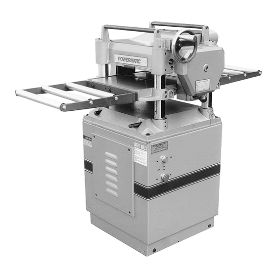
- Page 1 15" PLANER Model 15 Instruction Manual & Parts List M-0460213 (800) 248-0144 www.powermatic.com...
- Page 2 This manual has been prepared for the owner and operators of a Powermatic Model 15 Planer. Its purpose, aside from machine operation, is to promote safety through the use of accepted correct operating and maintenance procedures. Completely read the safety and maintenance instructions before operating or servicing the machine.
-
Page 3: Table Of Contents
Adjusting Cutting Head Parallel to Table ................12 Maintenance ............................ 13 Lubrication ..........................13 Parts Lists & Exploded Views: Base Assembly ........................14-15 Head Assembly ........................16-18 Table Assembly ........................19 Gear Box Assembly ......................20-21 Cabinet Assembly ......................22-23... -
Page 4: Safety: General Rules
SAFETY: General Rules USE SAFETY GLASSES. Also use face or dust mask if cutting operation is dusty. As with all power tools there is a certain amount of hazard involved with the operation and use of the SECURE WORK. Use clamps or a vise to hold tool. -
Page 5: Specific Rules
* Lead from lead-based paint. REMOVE SHAVINGS only with the power "off". * Crystalline silica from bricks and cement and Use a brush, not hands, to clear chips and shav- other masonry products. ings. * Arsenic and chromium from chemically-treated lumber. -
Page 6: Features
Cutterhead diameter ................. 2-7/8" Cuts per minute ..................13,500 Cutterhead S.F.M..................3,385 Knives ..................3, double sided Knife size ..................15" x 1" x 1/8" Bed roller diameter .................1-11/64" Feed roller diameter ................1-31/32" Feed speeds ................(2) 16 & 20 FPM Maximum depth of cut .................. -
Page 7: Receiving The Planer
RECEIVING THE PLANER CAUTION: Care must be taken when clean- ing the cutterhead. Knives are extremely sharp Remove the wood container surrounding the planer and can cause injury if not handled properly! and the boards holding it to the skid. STOCK RETURN ROLLERS Check for damage and ensure all parts are intact. -
Page 8: Electrical Connections
The Model 15 planer is designed to run on edge and the tables nor does the straight edge lie single phase 230 volt power only. Be sure that on the tables with the rollers lower on each end. -
Page 9: Adjustments
KNIFE ADJUSTMENT FEED RATE ADJUSTMENT CAUTION: Any adjustment or replacement The Model 15 is equipped with selectable feed of knives should be done to all three knives at the speed rollers that feed stock at 16 and 20 feet per same time. -
Page 10: Knife Removal & Installation
Disconnect machine from power source. ing straight out. A piece of scrap wood will aid Slightly loosen the five hex head screws (A). removal. See Figures 9 & 10. Insert new blade into cutterhead. Carefully place knife setting gauge (B) on Tighten five hex head screws (A). -
Page 11: Adjusting Outfeed Roller
Adjust Move the gauge block (D) under one end of equally on both ends of the roller. the outfeed roller, Figure 15. The bottom of the outfeed roller should just touch the top of the gauge block. -
Page 12: Adjusting Chipbreaker
ADJUSTING TABLE ROLLERS The chipbreaker is located just in front of the The Model 15 has two table rollers which aid in cutterhead. It raises as stock is fed through and feeding the stock by reducing friction and turn as "breaks"... -
Page 13: Maintenance
MAINTENANCE Move gauge block to opposite end of table. Distance from table to edge of head casting should be the same. Buildup of sawdust and other debris can cause your Repeat steps 2 and 3 on outfeed end of table. machine to plane inaccurately. -
Page 14: Parts Lists & Exploded Views: Base Assembly
PARTS LIST: Base Assembly (15 Planer) NO. PART NO. DESCRIPTION NO. PART NO. DESCRIPTION 6284703 Base 6284717 Sprocket 6284704 Screw, Set M10-1.5P-10 6284718 Washer, 3/8-20-1.5 6284705 Column, Crank Case 6284719 Nut, Hex Hd. M10-1.25 6284706 Column 6284720 Washer, 8.2-22-3 6284707 Screw, Lead 6284721 Bolt, Hex Hd. - Page 15 EXPLODED VIEW: Base Assembly (15 Planer)
-
Page 16: Head Assembly
PARTS LIST: Head Assembly (15 Planer) NO. PART NO. DESCRIPTION NO. PART NO. DESCRIPTION 6284752 Assembly, Cutterhead 6284797 Bearing 6284753 Case, Roller 6284798 Ring, Retainer, RTW-30 6284704 Screw, Set M10-1.5P-10 6284799 Handwheel 6284754 Cutterhead 6284828 Handle, 3/8"-16NC 6284755 Gib, Cutterhead Assembly... - Page 17 EXPLODED VIEW: Head Assembly View #1 (15 Planer)
- Page 18 EXPLODED VIEW: Head Assembly View #2 (15 Planer)
- Page 19 PARTS LIST: Table Assembly (15 Planer) NO. PART NO. DESCRIPTION NO. PART NO. DESCRIPTION 6284731 Table 6284742 Roller 6284732 Roller, Table 6284743 Bushing, Roller 6284733 Bearing 6284744 Shaft, Roller 6284734 Adjuster, Eccentric 6284745 Washer, 1/4"-16-1 6284735 Screw, Set M6-1.0P-12 6284746 Bolt, Hex Hd., M6-1.0P-12 6284737 Nut, Lock 6284747 Bolt, Soc.
-
Page 20: Gear Box Assembly
PARTS LIST: Gear Box Assembly (15 Planer) NO. PART NO. DESCRIPTION NO. PART NO. DESCRIPTION 6284842 Assembly, Gear Box 6284859 Shaft, Gear 6284803 Bolt, Soc. Hd., M8-1.25-50 6284860 Seal, Oil SC25-47-6 6284843 Seal, Oil TC28-40-8 6284861 Bearing 6284844 Plug, NPT, PT1/4"-19... - Page 21 EXPLODED VIEW: Gear Box Assembly (15 Planer)
-
Page 22: Cabinet Assembly
PARTS LIST: Cabinet Assembly (15 Planer) NO. PART NO. DESCRIPTION NO. PART NO. DESCRIPTION 6284892 Nut, Locking, 3/8"-16NC 6284875 Assembly, Cabinet 6284876 Cabinet 6284893 Lock, Wheel, 38-5/16-18NC-3/4 6284894 Cord, Power, 12A/3C-2.8M-2R4Y 6284877 Door 6284895 Relief, Strain, SB7R-3 6284911 Screw, Flat Hd. M6 x 1.0P x 12... - Page 23 EXPLODED VIEW: Cabinet Assembly (15 Planer)
- Page 24 WMH Tool Group 427 Sanford Road LaVergne, TN 37086 Phone: (800) 248-0144 Fax: (800) 274-6840 E-mail: powermatic@wmhtoolgroup.com Website: www.powermatic.com ® POWERMATIC 2001 January ALL RIGHTS RESERVED...
Need help?
Do you have a question about the 15 and is the answer not in the manual?
Questions and answers