Table of Contents
Advertisement
Quick Links
Advertisement
Table of Contents

Related Manuals for DeDietrich NeOvo EcoNox EFU 36


Summary of Contents for DeDietrich NeOvo EcoNox EFU 36
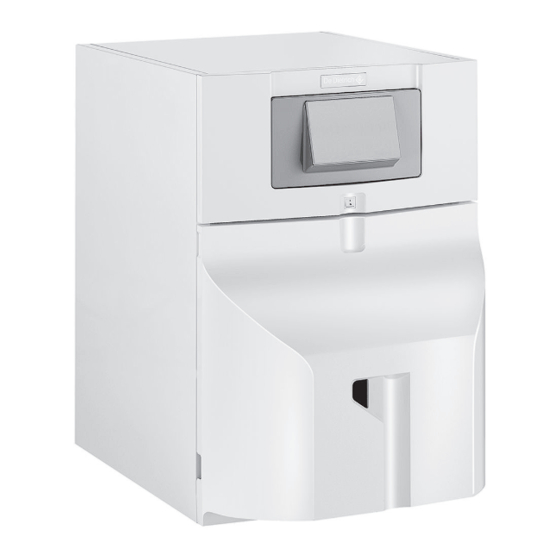
- Page 1 NeOvo User Manual Oil-fired boiler NeOvo EcoNox EFU 36 EFU 46...
- Page 2 Dear customer, Thank you for purchasing this appliance. Please read this manual carefully before using the product and keep it in a safe place for future reference. In order to ensure continued safe and efficient operation we recommend that the product is regularly maintained. Our Service and After Sales organization can assist with this.
-
Page 3: Table Of Contents
Contents Contents 1 Safety ................5 1.1 General safety instructions . - Page 4 Contents Control panel settings IniControl 2 ..............28 List of parameters .
-
Page 5: Safety
1 Safety 1 Safety 1.1 General safety instructions Danger This appliance is not intended for use by persons (in cluding children) with reduced physical, sensory or mental capabilities, or lack of experience and knowl edge, unless they have been given supervision or in struction concerning use of the appliance by a person responsible for their safety. -
Page 6: Recommendations
1 Safety Note Respect the minimum and maximum water inlet pres sure to ensure correct operation of the boiler: refer to the chapter Technical Specifications. Caution Do not neglect to service the boiler. Contact a quali fied professional or subscribe to a maintenance con tract for the annual servicing of the boiler. -
Page 7: Liabilities
1 Safety Caution If the home is unoccupied for a long period and there is a risk of frost, drain the boiler and the heating sys tem. 1.3 Liabilities 1.3.1 Manufacturer's liability Our products are manufactured in compliance with the re quirements of the various Directives applicable. -
Page 8: About This Manual
2 About this manual About this manual General This manual is intended for users of EFU boilers. Note The user guide can also be found on our internet site. Symbols used 2.2.1 Symbols used in the manual This manual uses various danger levels to draw attention to special in structions. -
Page 9: Technical Specifications
3 Technical specifications Technical specifications Homologations 3.1.1 Certifications Tab.1 Certifications CE identification number 0085CQ0004 Type of connection 3.1.2 Directives This product complies with the requirements of the following European Di rectives and Standards: Pressure Equipment Directive 97/23/EC, Article 3, paragraph 3 European New Approach Directive 98/70/EC 13/10/1998: Directive on petrol and diesel fuel quality Efficiency Directive 92/42/EC... - Page 10 3 Technical specifications Product name EFU 36 EFU 46 Low-temperature boiler B1 boiler Cogeneration space heater Combination heater Rated heat output Prated Useful heat output at rated heat output and high tem 37.2 46.4 perature regime Useful heat output at 30% of rated heat output and low 11.6 14.5 temperature regime...
- Page 11 3 Technical specifications Unit EFU 36 EFU 46 Minimum operating pressure MPa (bar) 0.05 (0.5) 0.05 (0.5) Maximum operating pressure MPa (bar) 0.3 (3) 0.3 (3) Maximum water temperature °C Pressure loss of hydraulic circuit at Δt = 10K mbar Pressure loss of hydraulic circuit at Δt = 15K mbar Pressure loss of hydraulic circuit at Δt = 20K...
-
Page 12: Description Of The Product
4 Description of the product Description of the product General description The floor-standing oil boilers in the EFU range have the following specifi cations: Heating only with possibility to produce domestic hot water by combining them with a domestic hot water tank High-efficiency heating Low polluting emissions Heating body in cast iron... -
Page 13: Burner
4 Description of the product 4.2.2 Burner Fig.3 Main components 1 Wiring base frame and control and safety control box 2 Ignition transformer 4 5 6 7 8 3 Component plate 4 N/A 5 Nozzle line 6 Ignition electrode 7 Nozzle 8 Combustion head 9 Flame pipe 10 Head air pressure measurement point... -
Page 14: Description Of The Display
4 Description of the product 4.3.2 Description of the display Fig.5 Display Hour run meter Failures Maintenance Reset necessary Burner status Heating mode Outside temperature sensor Domestic hot water mode MW-3000235-1 Description of the control panel IniControl 2 4.4.1 Description of the keys Fig.6 Control panel keys MW-1000043-4... - Page 15 4 Description of the product Burner Operation Fig.8 Burner Operation Burner OFF Burner ON MW-1000085-2 Operating modes Fig.9 Operating modes Steady symbol: heating function enabled Flashing symbol: heating production running Steady symbol: domestic hot water function enabled Flashing symbol: domestic hot water production running Heating function disabled Domestic hot water function disabled MW-1000083-3...
- Page 16 4 Description of the product Other Information Fig.12 Other Information Chimney Sweep Menu: forced operation in full load mode Access to information on the additional PCBs Name of the PCB for which the parameters are displayed Three-way valve connected Pump running MW-5000038-2 7642066 - v01 - 29092015...
-
Page 17: Utilisation With The Control Panel B-Control
5 Utilisation with the control panel B-Control Utilisation with the control panel B-Control Use of the control panel 5.1.1 Accessing the menus Fig.13 Press the 1. The key is used to access the various menus and to scroll up and down the information in the Information menu. -
Page 18: Shutdown
5 Utilisation with the control panel B-Control Shutdown 5.3.1 Switching off the heating Fig.16 Switching off the heating 1. Turn the setting button all the way to the left until is dis played. Note The frost protection function continues to run MW-3000241-1 5.3.2 Stopping domestic hot water production Fig.17... - Page 19 5 Utilisation with the control panel B-Control 1. Put the boiler in frost protection mode. The standby function will be deactivated. The boiler will then only start up to protect itself from frost. Note To prevent the radiators and the installation from freezing in pla ces where that risk exists (e.g.
-
Page 20: Utilisation With The Control Panel Inicontrol 2
6 Utilisation with the control panel IniControl 2 Utilisation with the control panel IniControl 2 Use of the control panel 6.1.1 Browsing in the menus Note The first time a key is pressed, the backlit screen is switched on. The name of the PCB is displayed: check that it is actually the PCB on which the setting must be made. -
Page 21: Accessing The User Menu
6 Utilisation with the control panel IniControl 2 Fig.21 Confirming the menu or parameter 4. To confirm selection of the desired menu, sub-menu or parameter, press the key. Note If no keys are pressed for 3 minutes, the appliance returns to normal operating mode. -
Page 22: Accessing The Hour Run Meters / Timer Program / Clock Sub-Menus
6 Utilisation with the control panel IniControl 2 1. Access the menus by pressing the two keys on the right simultane ously. 2. Select the User menu by pressing the key until the icon flashes. Fig.25 Accessing the User menu 3. -
Page 23: Shutdown
6 Utilisation with the control panel IniControl 2 4. Open the oil inlet valve. 5. Switch on the boiler. 6. A venting cycle is run automatically. 7. The display shows the operating status of the boiler, the heating flow temperature and any error codes. Shutdown 6.3.1 Switching off the heating Note... -
Page 24: Stopping Domestic Hot Water Production
6 Utilisation with the control panel IniControl 2 For more information, see Browsing in the menus, page 20 6.3.2 Stopping domestic hot water production Note The name of the PCB is displayed. Check that it is actually the PCB on which the setting must be made. Fig.32 Selecting the shut-down mode 1. -
Page 25: Frost Protection
6 Utilisation with the control panel IniControl 2 6. Remove the pipe connecting the boiler to the chimney and plug the flue gas nozzle. 7. Keep the area frost-free. Frost Protection If the central heating system is not in use and there is a risk of frost, we recommend activating the boiler's antifreeze protection function. -
Page 26: Control Panel Settings B-Control
7 Control panel settings B-Control Control panel settings B-Control List of parameters 7.1.1 Information menu Tab.11 Information list Information Description Status Sub-status °C Heating water temperature (°C) symbol flashes °C Domestic hot water temperature (°C) symbol flashes If no domestic hot water sensor connected: display — — — °C Outside temperature (°C) symbol flashes. -
Page 27: Modifying The Domestic Hot Water Temperature Set Point
7 Control panel settings B-Control Fig.36 Back to the main display 2. Go back to the main display by pressing the key for two seconds. Note After five seconds without pressing any keys on the control panel, the display goes back to the main display. MW-3000244-1 7.2.2 Modifying the domestic hot water temperature set point A lower domestic hot water temperature may be sufficient to meet the... -
Page 28: Control Panel Settings Inicontrol 2
8 Control panel settings IniControl 2 Control panel settings IniControl 2 List of parameters 8.1.1 Menu List Information menu User menu Installer menu Manual Forcing menu Failure menu Hour run meters sub-menu Timer Program sub-menu Clock sub-menu 8.1.2 Information menu Certain parameters are displayed: according to certain system configurations, according to the options, circuits or sensors actually connected. -
Page 29: Counters / Time Prog / Menus Clock
8 Control panel settings IniControl 2 Parameters Description Factory setting Customer setting AP017 Domestic hot water tank operation: 0 = OFF 1 = ON AP073 SUMMER / WINTER set point switch: 22°C Can be set from 15 to 30°C Set to 30.5°C = function deactivated AP074 SUMMER override: 0 = OFF... - Page 30 8 Control panel settings IniControl 2 Sub-menu COUNTERS Tab.14 List of parameters Parameters Description Unit DC002 Number of reversal valve cycles DC003 Number of hours' reversal valve operation hours PC002 Number of burner start-ups DC004 Number of burner start-ups in domestic hot water production mode PC003 Number of hours' operation hours...
-
Page 31: Pcb Parameters For The Pcb + Sensor Kit For Circuits With Mixing Valve
8 Control panel settings IniControl 2 8.1.5 PCB parameters for the PCB + sensor kit for circuits with mixing valve Certain parameters are displayed: according to certain system configurations, according to the options, circuits or sensors actually connected. Tab.17 List of parameters accessible to the user Parameters Description Factory setting... -
Page 32: Setting The Heating
8 Control panel settings IniControl 2 Fig.39 Displaying the User menu 2. Select the desired parameter by pressing to scroll through the list of parameters that can be adjusted. 3. Confirm the selection by pressing 4. Modify the value of the parameter by pressing 5. -
Page 33: Activating Manual Forcing
8 Control panel settings IniControl 2 Fig.43 Confirmation of the domestic hot wa 2. Display the domestic hot water production circuit parameters by ter circuit pressing the key. The name of the circuit and the domestic hot water temperature set point are displayed alternately. -
Page 34: Setting The Timer Program
8 Control panel settings IniControl 2 For more information, see Browsing in the menus, page 20 8.2.5 Setting the timer program Note The name of the PCB is displayed. Check that it is actually the PCB on which the setting must be made. Fig.47 Accessing the Hour Run Meters / 1. - Page 35 8 Control panel settings IniControl 2 Sunday Note key is used to move to the right. Note key is used to move to the left. Fig.51 Setting the time 5. Set the start time for the period S1 by pressing the key.
-
Page 36: Maintenance
9 Maintenance Maintenance General We recommend having the boiler inspected and serviced at regular inter vals. Boiler maintenance and cleaning must be carried out at least once a year by a qualified professional. Have an inspection carried out and the flues swept at least once a year or more, depending on the regulations in force in your country. -
Page 37: Chimney Sweep Instructions
9 Maintenance 9.2.3 Chimney sweep instructions Check the combustion each time the flues are swept. Venting the installation Fig.54 Venting the installation Any air in the appliance, the pipes or the valves must be removed in order to prevent annoying noises that may occur during heating or when tapping water. -
Page 38: Draining The Installation
9 Maintenance Draining the installation Fig.55 Draining the installation It may be necessary to drain the central heating installation if radiators need to be replaced, if there is a major water leak or if there is a risk of freezing. Proceed as follows: 1. -
Page 39: Troubleshooting
10 Troubleshooting 10 Troubleshooting 10.1 Error messages B-Control 10.1.1 Shutdown A shutdown is a (temporary) boiler status, resulting from an abnormal state. The display shows a shutdown code. The control unit makes a num ber of attempts to start the boiler again. Note The boiler automatically returns to operation once the cause of the shutdown has been removed. -
Page 40: Error Messages Inicontrol 2
10 Troubleshooting Fig.57 Fault code display MW-6000210-2 10.2 Error messages IniControl 2 10.2.1 Error messages Fig.58 Restarting the appliance 1. Press for 3 seconds to restart the appliance. MW-5000060-2 Fig.59 Error code display Note The message appears when a failure code is detected. After resolving the problem, pressing the key resets the appliance's functions and thus eradicates the failure. -
Page 41: Error History
10 Troubleshooting Fig.61 Displaying the error messages 2. Press the key to scroll through the error and fault messages. For more information, see Browsing in the menus, page 20 MW-5000043-1 10.2.3 Error history Fig.62 Accessing the menus 1. Access the menu level by pressing the two keys on the right simulta neously. -
Page 42: Decommissioning
11 Decommissioning 11 Decommissioning 11.1 Decommissioning procedure Fig.64 Cutting the mains power supply If you need to decommission the boiler, either temporarily or permanently, proceed as follows: 1. Switch the On/Off switch to Off. 2. Switch off the mains supply to the boiler. 3. -
Page 43: Disposal
12 Disposal 12 Disposal 12.1 Disposal and Recycling Fig.65 Recycling Warning Removal and disposal of the boiler must be carried out by a quali fied installer in accordance with local and national regulations. MW-3000179-03 7642066 - v01 - 29092015... -
Page 44: Energy Savings
13 Energy savings 13 Energy savings Tips on saving energy: Do not block ventilation outlets. Do not cover the radiators. Do not hang curtains in front of the radiators. Install reflective panels behind the radiators to prevent heat losses. Insulate the pipes in rooms that are not heated (cellars and lofts). Turn off the radiators in rooms not being used. -
Page 45: Warranty
14 Warranty 14 Warranty 14.1 General We would like to thank you for buying one of our appliances and for your trust in our product. In order to ensure continued safe and efficient operation we recommend that the product is regularly inspected and maintained. Your installer and our service department can assist with this. -
Page 46: Appendix
15 Appendix 15 Appendix 15.1 Product fiche Tab.18 Product fiche for boiler space heaters Brand name - Product name EFU 36 EFU 46 Seasonal space heating energy efficiency class (Prated or Psup) Rated heat output Seasonal space heating energy efficiency Annual energy consumption Sound power level L indoors... -
Page 47: Product Fiche
15 Appendix 15.2 Product fiche Fig.66 The boiler's product fiche indicates the space heating energy efficiency of the product. Seasonal space heating energy effi ciency of boiler ‘I’ Temperature control Class I = 1%, Class II = 2%, Class III = 1.5%, Class IV = 2%, Class V = 3%, Class VI = 4%, from fi... - Page 48 15 Appendix The factor for weighting the heat output of preferential and supple mentary heaters of a package as set out in the following table. The value of the mathematical expression: 294/(11 · Prated), whereby ‘Prated’ is related to the preferential space heater. The value of the mathematical expression 115/(11 ·...
-
Page 49: V01 - 29092015 Efu
15 Appendix 7642066 - v01 - 29092015... - Page 50 15 Appendix 7642066 - v01 - 29092015...
- Page 51 © Copyright All technical and technological information contained in these technical instructions, as well as any drawings and technical de scriptions supplied, remain our property and shall not be multiplied without our prior consent in writing. Subject to alterations.
- Page 52 Зубарев переулок, д. 15/1 +49 (0)25 72 / 9161-0 Бизнес-центр «Чайка Плаза», +49 (0)25 72 / 9161-102 офис 309 info@remeha.de +7 (495) 221-31-51 info@dedietrich.ru DE DIETRICH THERMIQUE Iberia S.L.U. DE DIETRICH SERVICE www.dedietrich-calefaccion.es www.dedietrich-heiztechnik.com Freecall 0800 / 201608 C/Salvador Espriu, 11 08908 L’HOSPITALET de LLOBREGAT...
Need help?
Do you have a question about the NeOvo EcoNox EFU 36 and is the answer not in the manual?
Questions and answers