Sony XR-5790R Service Manual
Fm/mw/lw cassette car stereo
Hide thumbs
Also See for XR-5790R:
- Operating instructions manual (72 pages) ,
- Service manual (44 pages)
Table of Contents
Advertisement
SERVICE MANUAL
Dolby noise reduction manufactured under license
from Dolby Laboratories Licensing Corporation.
"DOLBY" and the double-D symbol a are trade-
marks of Dolby Laboratories Licensing Corporation.
MICROFILM
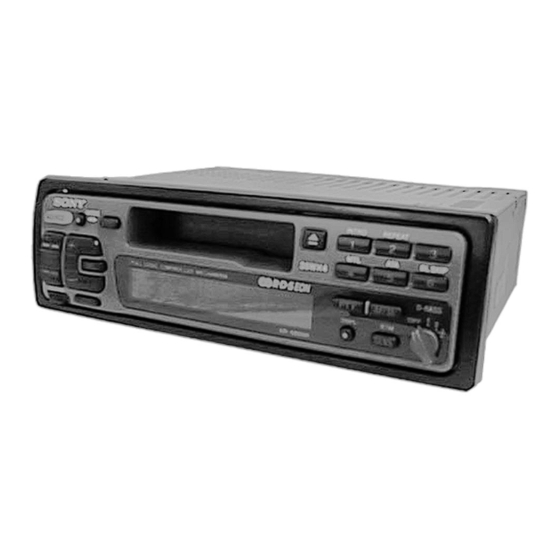
XR-5790R/5800R
Photo: XR-5800R
SPECIFICATIONS
FM/MW/LW CASSETTE CAR STEREO
Model Name Using Similar Mechanism
Tape Transport Mechanism Type
AEP Model
UK Model
NEW
MG-25G-136
Advertisement
Table of Contents

Related Manuals for Sony XR-5790R


Summary of Contents for Sony XR-5790R
- Page 1 XR-5790R/5800R SERVICE MANUAL AEP Model UK Model Photo: XR-5800R Dolby noise reduction manufactured under license Model Name Using Similar Mechanism from Dolby Laboratories Licensing Corporation. Tape Transport Mechanism Type MG-25G-136 “DOLBY” and the double-D symbol a are trade- marks of Dolby Laboratories Licensing Corporation.
-
Page 2: Table Of Contents
6-1. Printed Wiring Boards – Main Section – ....... 22 6-2. Schematic Diagram – Main Section – ......25 6-3. Printed Wiring Board – Panel Section – (XR-5790R) .. 30 6-4. Schematic Diagram – Panel Section – (XR-5790R) ..32 6-5. - Page 3 SECTION 1 This section is extracted from instruction manual. GENERAL – 3 –...
- Page 4 – 4 –...
- Page 5 – 5 –...
- Page 6 – 6 –...
- Page 7 (XR-5800R only) – 7 –...
- Page 8 – 8 –...
-
Page 9: Disassembly
SECTION 2 DISASSEMBLY Note: Follow the disassembly procedure in the numerical order given. FRONT PANEL ASS’Y 1 Push the button (release). 2 Remove the front panel ass’y to the direction of the arrow A . COVER ASS’Y 3 cover ass’y –... - Page 10 SUB PANEL, MECHANISM DECK (MG-25G-136) 5 screw (PTT2.6 × 6) 3 connector (CN352) 6 mechanism deck (MG-25G-136) 4 flexible flat cable (CN351) 2 sub panel 1 three screws (PTT2.6 × 8) 1 three screws (PTT2.6 × 8) 5 four screws (PTT2.6 ×...
-
Page 11: Assembly Of Mechanism Deck
SECTION 3 ASSEMBLY OF MECHANISM DECK Note: Follow the assembly procedure in the numerical order given. HOUSING 7 Holder the hanger by bending the claw. 5 Fit projection on C part. 1 Install the catch to the hanger. 2 Install the hanger onto two claws of the housing. - Page 12 LEVER (LDG-A) / (LDG-B) shaft A shaft B shaft C shaft A shaft B 1 Fit the lever (LDG-A)on shafts A – C and install it. 3 type-E stop ring 2.0 2 Fit the lever (LDG-B) on shafts A and B and install it.
- Page 13 GUIDE (C) 2 guide (C) 1 three claws – 13 –...
-
Page 14: Mechanical Adjustments
SECTION 4 SECTION 5 MECHANICAL ADJUSTMENTS ELECTRICAL ADJUSTMENTS 1. Clean the following parts with a denatured-alcohol-moistened TEST MODE swab: This set have the test mode function. In the test mode, FM Auto playback head pinch roller Scan/Stop Level and AM (MW) Auto Scan/Stop Level adjustments rubber belt capstan can be performed easier than it in ordinary procedure. -
Page 15: Tuner Section
FM Noise Focus Adjustment TUNER SECTION 0 dB=1 µV Setting: [SOURCE] button: FM Cautions during repair When the tuner unit is defective, replace it by a new one be- FM RF signal cause its internal block is difficult to repair. level meter antenna jack (J1) generator... - Page 16 FM Signal Meter Adjustment AM (MW) Auto Scan/Stop Level Adjustment Setting: Make this adjustment after “FM Auto Scan/Stop Level Adjust- [SOURCE] ment”. button: FM Setting: FM RF signal [SOURCE] button: MW generator antenna jack (J1) 30 Ω 15 pF 0.01 µ F 65 pF Carrier frequency : 98.00 MHz : 35 dB (56.2 µ...
- Page 17 Adjustment Location: – SET UPPER VIEW – Tape Speed Adjustment RV1 AM (MW) Auto Scan/Stop Level Adjustment RV2 FM Auto Scan/Stop Level Adjustment RV3 FM Noise Focus Adjustment RV4 FM Stereo Separation Adjustment RV1 FM Signal Meter Adjustment – 17 –...
-
Page 18: Diagrams
SECTION 6 DIAGRAMS • IC Block Diagrams – MAIN Board – IC1 TB2114F (EL) 24 23 21 20 14 13 RIPPLE FILTER – – SEEK/RECP SEEK/RECP 4BIT SWALLOW MODULAS COUNTER PRESCALER 12BIT PHASE PROGRAMABLE COMPARATOR COUNTER REFERENCE 40BIT 18BIT 20BIT COUNTER 22BIT SHIFT... - Page 19 IC151 LC75373ED – LFIN – – – LFOUT – LSELO LROUT – – – VREF SHIFT DECODER LATCH CONTROL REGISTER – – – RROUT RSELO – RFOUT – – – – RFIN 6 7 8 9 10 IC351 CXA2509AQ-T4 24dB 120µ/70µ...
- Page 20 IC360 MM1322XFBE 8 OUT2 OUT1 IC601 BA3918-V2 REGULATOR OVER VOLTAGE PROTECT – 2 3 4 – 20 –...
- Page 21 • Waveforms 1 IC1 1 XO 2 IC3 9 XO 42 mVp-p 5.1 Vp-p 200 ns 230 ns 3 IC501 9 X OUT 4 IC501 !™ XT OUT 5 Vp-p 3.9 Vp-p 30.6 µ s 125 ns – 21 –...
- Page 26 • MAIN BOARD IC501 MN1884820SC (SYSTEM CONTROLLER) Pin No. Pin Name Function TUNMUT FM audio signal muting control output terminal “H”: muting on AMPON Standby control signal output to the power amplifier (IC801) “L”: standby Power supply on/off control signal output terminal at the illumination and liquid crystal display driver (IC901) “H”: power on ILLON At power select switch (S801) on mode: “H”...
- Page 27 AVREF+ Reference voltage input terminal (+5V) (for A/D converter) Key input terminal (A/D input) XR-5790R: 6, INTRO 1, REPEAT 2, 3, BL SKIP 6, ATA 5, 4, PTY, AF/TA, PRST +/–, DSPL keys input (LSW921 to LSW932) KEYIN1 XR-5800R: 6, INTRO 1, REPEAT 2, 3, BL SKIP 6, ATA 5, MTL 4, PTY, AF/TA, BTM...
- Page 28 Pin No. Pin Name Function AF SEK AF seek control signal output terminal Not used (open) COLOR Setting terminal for the illumination color “L”: amber, “H”: green Not used (open) NOSESW Detects the removal of the attaching and removing type front panel block “L”: attaching Input of FM stereo detection signal from FM/AM tuner unit (TU1), and output of forced monaural control signal to FM/AM tuner unit (TU1) (Commonly used for stereo display input ST IN...
-
Page 29: Exploded Views
SECTION 7 EXPLODED VIEWS NOTE: • Items marked “*” are not stocked since they • -XX and -X mean standardized parts, so they may have some difference from the original are seldom required for routine service. Some one. delay should be anticipated when ordering these items. - Page 30 (2) FRONT PANEL SECTION (XR-5790R) not supplied (KEY board) LCD901 Ref. No. Part No. Description Remark Ref. No. Part No. Description Remark 3-018-930-01 KNOB (D-BASS) 3-010-389-01 BUTTON (P. A. P) (PTY. AF/TA. –. PRST. +) * 52 3-014-857-01 SHEET (LCD) (T)
- Page 31 (3) FRONT PANEL SECTION (XR-5800R) not supplied (KEY board) LCD901 not supplied Ref. No. Part No. Description Remark Ref. No. Part No. Description Remark 3-018-799-01 BUTTON (D-BASS) 3-016-927-01 BUTTON (1-3) (6. 1. 2. 3) 3-015-036-01 CUSHION (BACK PANEL) 3-016-928-11 BUTTON (4-6) (4. 5. 6) 3-016-924-01 BUTTON (L) (2) (+.
- Page 32 (4) MECHANISM DECK SECTION (MG-25G-136) HP901 M901 Ref. No. Part No. Description Remark Ref. No. Part No. Description Remark A-3291-667-A CLUTCH (FR) ASSY 3-933-346-01 CATCHER * 152 3-019-130-01 LEVER (LDG-A) 3-933-344-01 GUIDE (C) * 153 3-019-131-01 LEVER (LDG-B) 3-014-798-01 SCREW (HEAD), SPECIAL 3-020-539-01 SPRING (LD-1), TENSION 3-364-151-01 WASHER 3-020-540-01 SPRING (LD-2), TENSION...
-
Page 33: Electrical Parts List
SECTION 8 ELECTRICAL PARTS LIST NOTE: When indicating parts by reference • Due to standardization, replacements in the • Items marked “*” are not stocked since they number, please include the board. parts list may be different from the parts speci- are seldom required for routine service. - Page 34 Ref. No. Part No. Description Remark Ref. No. Part No. Description Remark LSW922 1-762-619-11 SWITCH, KEY BOARD (WITH LED) (INTRO, 1) R903 1-216-045-00 METAL CHIP 1/10W (GREEN) R904 1-216-049-11 RES, CHIP 1K (2012) LSW923 1-762-617-11 SWITCH, KEY BOARD (WITH LED) (REPEAT, 2) R905 1-216-053-00 METAL CHIP 1.5K...
- Page 35 MAIN Ref. No. Part No. Description Remark Ref. No. Part No. Description Remark R973 1-216-025-00 RES, CHIP 100 (2012) (5800R: GREEN) 1-164-232-11 CERAMIC CHIP 0.01uF R973 1-216-029-00 METAL CHIP 1/10W (5800R: AMBER) 1-163-251-11 CERAMIC CHIP 100PF R974 1-216-025-00 RES, CHIP 100 (2012) (5800R: GREEN) C101 1-163-037-11 CERAMIC CHIP...
- Page 36 MAIN Ref. No. Part No. Description Remark Ref. No. Part No. Description Remark C405 1-164-489-11 CERAMIC CHIP 0.22uF D613 8-719-034-94 DIODE MA4180-M(QZ) C408 1-126-160-11 ELECT C409 1-163-009-11 CERAMIC CHIP 0.001uF D614 8-719-109-97 DIODE RD6.8ES-B2 C410 1-164-161-11 CERAMIC CHIP 0.0022uF 10% 100V D615 8-719-109-97 DIODE RD6.8ES-B2...
- Page 37 MAIN Ref. No. Part No. Description Remark Ref. No. Part No. Description Remark JC40 1-216-295-11 SHORT (CHIP) 0 Q702 8-729-020-67 TRANSISTOR XN1A312-TX JC50 1-216-296-00 SHORT (CHIP) 0 JC51 1-216-296-00 SHORT (CHIP) 0 < RESISTOR > JC52 1-216-296-00 SHORT (CHIP) 0 1-216-049-11 RES, CHIP 1K (2012) JC53...
- Page 38 MAIN POWER Ref. No. Part No. Description Remark Ref. No. Part No. Description Remark R365 1-216-065-00 METAL CHIP 4.7K 1/10W R601 1-216-057-00 METAL CHIP 2.2K 1/10W R403 1-216-077-00 METAL CHIP 1/10W R602 1-216-097-00 RES, CHIP 100K (2012) R404 1-216-081-00 METAL CHIP 1/10W R603 1-216-089-00 RES, CHIP...
- Page 39 POWER Ref. No. Part No. Description Remark Ref. No. Part No. Description Remark C812 1-163-009-11 CERAMIC CHIP 0.001uF C821 1-163-009-11 CERAMIC CHIP 0.001uF ************** C822 1-163-009-11 CERAMIC CHIP 0.001uF HARDWARE LIST ************** < CONNECTOR > 7-621-772-10 SCREW +B 2X4 CN801 1-778-985-11 PIN, CONNECTOR (ISO) 7-685-793-09 SCREW +PTT 2.6X8 (S) CN802...
- Page 40 Ref. No. Part No. Description Remark PARTS FOR INSTALLATION AND CONNECTIONS ************************************** 3-916-161-31 FRAME ASSY X-3370-077-1 SCREW ASSY (AE. KEY), FITTING 1-777-989-31 CORD (WITH CONNECTOR) (ATT) (5800R) 1-782-093-11 CORD (WITH CONNECTOR) (ISO-S) (SPEAKER) 1-782-092-11 CORD (WITH CONNECTOR) (ISO-P) (POWER) X-3373-432-1 BRACKET ASSY (for RM-X4S) (5800R: AEP, UK, South European) 1-465-459-21 ADAPTER, ANTENNA XR-5800R: AEP, UK, South European...
- Page 41 XR-5790R/5800R Sony Corporation 97L0542-1 9-925-675-11 Personal & Mobile Communication Company Printed in Japan © 1997. 12 – 54 – Published by Quality Assurance Dept.
Need help?
Do you have a question about the XR-5790R and is the answer not in the manual?
Questions and answers