Table of Contents
Advertisement
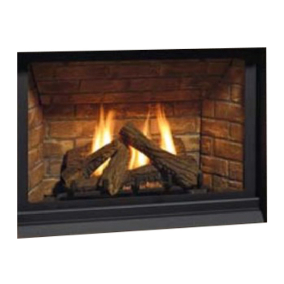
Regency P33CE
WARnInG
FIRE OR ExPLOSIOn HAzARD
Failure to follow safety warnings exactly could result in serious
injury, death, or property damage.
- Do not store or use gasoline or other flammable vapors and liquids in the vicinity of this or any other
appliance.
- WHAT TO DO IF YOU SMELL GAS
•
Do not try to light any appliance.
• Do not touch any electrical switch: do not use any phone in your building.
Leave the building immediately.
• Immediately call your gas supplier from a neighbour's phone. Follow the gas supplier's
instructions.
• If you cannot reach you gas supplier, call the fire department.
- Installation and service must be performed by a qualified installer, service agency or the gas supplier.
Tested by:
919-364
fpi fireplace products international ltd. 6988 Venture st., delta, Bc canada, V4G 1H4
Gas Fireplace
Installer: Please complete the details on the back cover
and leave this manual with the homeowner.
Homeowner: Please keep these instructions for future reference.
Owners &
Installation Manual
3
MODEL: P
3CE-NG10 Natural Gas
3
P
3CE-LP10 Propane
Panorama P33CE
www.regency-fire.com
09.18.14
Advertisement
Table of Contents

Related Manuals for Regency P33CE-NG10


Summary of Contents for Regency P33CE-NG10
- Page 1 Owners & Regency P33CE Installation Manual Gas Fireplace MODEL: P 3CE-NG10 Natural Gas 3CE-LP10 Propane Panorama P33CE www.regency-fire.com WARnInG FIRE OR ExPLOSIOn HAzARD Failure to follow safety warnings exactly could result in serious injury, death, or property damage. - Do not store or use gasoline or other flammable vapors and liquids in the vicinity of this or any other appliance.
- Page 2 The P33CE has been approved by Warnock Hersey/Intertek for both safety and efficiency. As it also bears our own mark, it promises to provide you with economy, comfort and security for many trouble free years to follow. Please take a moment now to acquaint yourself with these instructions and the many features of your Regency Fireplace.
- Page 3 MoBile/Manufactured HoMes after first sale This Regency product has been tested and listed by Warnock Hersey/Intertek as a Direct Vent Wall Furnace to the following standards: ® VENTED GAS FIREPLACE HEATERS ANSI Z21.88-2014 • CSA 2.33-2014 and GAS-FIRED APPLIANCES FOR USE AT HIGH ALTITUDES CAN/CGA-2.17-M91.
-
Page 4: Table Of Contents
First Fire ..............44 Venting Introduction ........... 16 Aeration Adjustment ..........44 Exterior Vent Termination Locations ......17 Lighting Procedure ............ 45 Regency Direct Vent flex System ......18 Shutdown Procedure ..........45 ® Installation Procedures ..........19 Copy of the Lighting Plate Instructions ...... 46 Rigid Pipe Venting Systems ........ -
Page 5: Safety Label
The safety label is located on the front inside base of the unit, visible when the bottom louver is open. NOTE: Regency units are constantly being ® improved. Check the label on the unit and if there is a difference, the label on the unit is the correct one. -
Page 6: For The State Of Massachusetts Only
requirements MA Code - CO Detector (for the State of Massachusetts only) 5.08: Modifications to NFPA-54, Chapter 10 (2) Revise 10.8.3 by adding the following additional requirements: (a) For all side wall horizontally vented gas fueled equipment installed in every dwelling, building or structure used in whole or in part for residential purposes, including those owned or operated by the Commonwealth and where the side wall exhaust vent termination is less than seven (7) feet above finished grade in the area of the venting, including but not limited to decks and porches, the following requirements shall be satisfied:... -
Page 7: Important Message
In THE SAME AREA AS THE APPLI- ANCE. TODDLERS,YOUNG CHILDREN 4) This appliance must be connected to the speci- The P33CE-NG10 or P33CE-LP10 Direct Vent AnD OTHERS MAY BE SUSCEPTIBLE Fireplace must be installed in accordance with fied vent and termination cap to the outside of these instructions. -
Page 8: Installation Checklist
installation CAUTION: Any alteration to the product that Flat on Wall installation causes sooting or carboning that results Flat on Wall Corner cHecklist in damage is not the responsibility of the Recessed into Wall/Alcove manufacturer. Corner 1) Locate appliance a) Room location (Refer to "Locating Your Fireplace"... -
Page 9: Unit Dimensions
installation unit diMensions 23" 584mm 2-1/2" 34-9/16" [64mm] [878mm] NAILING STRIP 3" 76mm 26" 660mm 29-7/16" 747mm 4 sided faceplate diMensions 42-5/16" (1074mm) 2" (51mm) P33CE-10 Direct Vent Gas Fireplace... -
Page 10: Clearances
installation clearances The clearances listed below are Minimum distances unless otherwise stated: A major cause of chimney related fires is failure to maintain required clearances (air space) to combustible materials. It is of the greatest importance that this fireplace and vent system be installed only in accordance with these instructions. warninG Caution Requirements Fire hazard is an extreme risk... -
Page 11: Combustible Mantels
installation coMBustiBle Mantels Because of the extreme heat this fireplace emits, the mantel clearances are critical. Combustible mantel clearances from top of unit are shown in the diagram below. Note: A non-combustible mantel may be installed at a lower height if the framing is made of metal studs covered with a non-combustible board. This drawing is to scale at 1:6 (one inch = 6 inches). -
Page 12: Mantel Leg Clearances
installation Mantel leG clearances Combustible mantel leg clearances from side of unit as per diagram: Top View Side opening of Unit 6-3/4" Allowable mantel leg projection 9" 12 | P33CE-10 Direct Vent Gas Fireplace... -
Page 13: Framing Dimensions
installation fraMinG diMensions Non-combustible Header 2X4 HEADER (steel stud on edge) DETAIL N SCALE 1 : 6 NOTE: If this is an outside corner, the Floor minimum distance between the vent and the outside corner is 6" (15cm) with AstroCap termination cap or 12" (30cm) with Rigid Vent termination cap. -
Page 14: Framing & Finishing
installation fraMinG & finisHinG 1. There are 8 (eight) side nailing strips and one top nailing strip available on the unit. One set of four (4) are for a clean finish (board only, painted) installation, the other set are for a non-combustible finish (ex. tile, concrete, mantel, surround) as they are set back 1/2" (13mm). The top nailing strip is adjustable to 1/2"... - Page 15 installation 6) If applying a non-combustible facing it may be installed over the metal surface of the firebox of the unit in the area shown below. nOn-COMBUSTIBLE BOARD OnLY (PAInTED FInISH) WOOD STUD Combustible Material 1/2" DRYWALL DO NOT EXTEND Non-combustible Material (3-1/2"...
-
Page 16: Venting Introduction
There are 5 vent systems approved for use with the P33CE: the Regency Direct Vent Flex System for Horizontal Terminations only and the Simpson ®... -
Page 17: Exterior Vent Termination Locations
installation exterior Vent terMination locations Minimum Clearance Requirements Canada Clearance above grade, veranda, porch, deck, or balcony 12"(30cm) 12"(30cm) Clearance to window or door that may be opened 12"(30cm) 9" (23cm) Clearance to permanently closed window Vertical clearance to ventilated soffit located above the terminal within a horizontal distance of 2 feet (61cm) 18"(46cm) 18"(46cm) from the center line of the terminal (check with the local code) -
Page 18: Regency ® Direct Vent Flex System
Notes: 1) Liner sections should be continuous 6-7/8" without any joints or seams. (173mm) 2) Only Flex pipe purchased from Regency ® dia. Flue pipe may be used for Flex installations. See Figure 1 below for Alternate Caps. MInIMuM... -
Page 19: Installation Procedures
Regency Direct Vent System (Flex) ® 1) Locate the unit in the framing, rough in the gas *If this is an outside corner, the minimum distance between the vent and the outside (preferably on the right side of the unit) and the corner is 6"... -
Page 20: Rigid Pipe Venting Systems
installation riGid pipe VentinG systeMs Horizontal or Vertical Terminations The minimum components required for a basic horizontal termination are: Vertical Terminal AstroCap Horizontal Termination Cap Elbow Storm Collar Rigid Pipe Adaptor Vinyl Siding Wall Thimble Standoff (Optional) Length of pipe to suit wall thickness Flashing (see chart) For siding other than vinyl furring strips may be used,... -
Page 21: 4" X 6-5/8" Rigid Pipe Cross Reference Chart
Components from different Manufacturers may not be mixed. Not All Rigid Pipe components are available directly from FPI. 4” X 6- 5/8” RIGID PIPE CROSS REFERENCE CHART Components from different Manufacturers may not be mixed. Not all rigid pipe components are available directly from Regency. Description... - Page 22 Never allow the vent to run downward - this could cause high temperatures and may present a possible fi re hazard. Regency Fireplace Products . 6988 Venture St. . Delta, BC . Canada . V4G 1H4 . 604-946-5155 . www.regency-fi re.com...
-
Page 23: Rigid Pipe Venting Arrangements
installation riGid pipe VentinG arranGeMents Vertical Terminations (Propane & Natural Gas) The shaded area in the diagram shows all allowable combinations of straight vertical and offset to vertical terminations, using one 90 elbow, with rigid pipe vent systems for Propane and Natural Gas. •... - Page 24 installation The P33CE is approved for a maximum 40 ft. straight vertical, with rigid pipe vent systems for Propane and Natural Gas. The shaded area in the diagram shows all allowable combinations of straight vertical and offset to vertical terminations with rigid pipe vent systems for Propane and Natural Gas.
-
Page 25: Horizontal Terminations
Note: Must use optional rigid pipe adaptor (Part # 510-994) when using rigid pipe vent systems. (Refer "Rigid Pipe Venting Systems" Section) A vent guard should be used whenever the termination is lower than the specified minimum or as per local codes. Note: Regency Direct Vent System (Flex) ® is only approved for horizontal terminations. - Page 26 installation Horizontal Venting with Two (2) 90 Elbows Horizontal Venting with Three (3) 90 Elbows One 90 elbow = Two 45 elbows. One 90 elbow = Two 45 elbows. Option H + H1 Option H + H1 + H2 With these options, maximum With these options, maximum total pipe total pipe length is 30 feet...
- Page 27 installation Horizontal Venting with Three (3) 90 Elbows One 90 elbow = Two 45 elbows. Option V + V1 H + H1 With these options, maximum total pipe 2' Min. 1' Max. 3' Min. 4' Max. length is 30 feet with minimum of 12 feet 3' Min.
- Page 28 installation Vertical Venting with Three (3) 90 Elbows One 90 elbow = Two 45 elbows. Option H + H1 V + V1 With these options, max. total 1' Max. 1' Min. 3' Max. 3' Min. pipe length is 30 feet with min. 2' Max.
-
Page 29: Vertical Termination With Co-Linear Flex System
installation Vertical terMination witH co-linear flex systeM tHe appliance Must not Be Masonry chimneys may take various contours which the flexible liner will accommodate. However, connected to a cHiMney flue serVinG keep the flexible liner as straight as possible, avoid unnecessary bending. a separate solid fuel BurninG appliance. -
Page 30: Venting Arrangements - Vertical Terminations
installation VentinG arranGeMents - Vertical terMinations with Co-linear Flex System for both Residential & Manufactured Homes into Masonry Fireplaces Horizontal Distance (Feet) When using Contemporary Faceplate, unit must be raised 1". The shaded area in the diagrams show the allowable vertical terminations. 30 | P33CE-10 Direct Vent Gas Fireplace... -
Page 31: Unit Installation With Horizontal Termination
installation unit installation witH Horizontal terMination b) Horizontal runs of vent must be supported Install the vent system according to the Riser Vent every three feet. Wall straps are available Diagram 2a manufacturer's instructions included with the Termination for this purpose. components. -
Page 32: Unit Installation With Vertical Termination
installation 8) Slide the appliance and vent assembly towards 4) Assemble the desired lengths of pipe and the wall carefully inserting the vent pipe into the elbows. Ensure that all pipes and elbow con- vent cap assembly. It is important that the vent nections are in the fully twist-locked position pipe extends into the vent cap sufficient distance and sealed. -
Page 33: Pilot Adjustment
Gas pipe pressure P33CE-NG10 System Data testinG Periodically check the pilot flames. Correct Burner Inlet Orifice Sizes: flame pattern has two strong blue flames: Max. Input Rating 20,000 Btu/h 1 flowing around the flame sensor and 1... -
Page 34: Conversion From Ng To Lp
P33E installation Conversion from NG to LPG conVersion froM nG to lp for P33CE using SIT 886 NOVA Gas Valve For P33CE Using SIT 885 NOVA Gas Valve THIS CONVERSION MUST BE DONE BY A QUALIFIED GAS FITTER IF IN DOUBT DO NOT DO THIS CONVERSION!! Remove burner orifice with a 1/2"... -
Page 35: Optional Brick Panels
installation loG set installation optional Brick panels D) 251 A) 250 Read the instructions below carefully 1) Remove the mesh barrier and glass door. and refer to the diagrams. If logs Remove logs. are broken do not use the unit until they are replaced. - Page 36 installation 8) Pull off ember size pieces of rock wool and gently place them on the front of the burner tray in the places shown in the photo below. Do not compress the rock wool, leave it loose. Separate platinum embers and place them on the front of the burner on and around the rock wool.
-
Page 37: Glass Door And Mesh Barrier Installation
installation Glass door and MesH Barrier installation standard flusH door Use the hook to pull the spring out until you can put the hook into the slot on the bottom door bracket. Repeat for 2nd spring. See Diagram 4. Both the standard flush door comes with a black frame. Install the glass door by hooking the top door flange onto the top of the unit and swing the door towards the unit, Diagram 2. -
Page 38: Optional 4-Sided Faceplate Installation
installation optional 4-sided faceplate installation If installing the optional faceplate ensure the combustible 3. Line up the middle rib on backside of faceplate with middle indent on bracket. and non combustible material around the unit are installed flush with the unit. (See Diagram 1 below). This will centre the faceplate and allow 1/16"... -
Page 39: Wiring Diagram
installation wirinG diaGraM This heater does not require a 120V A.C. supply for operation but it is highly recommended to install the supplied AC adaptor to eliminate the need for batteries. In case of a power failure, the burner switch and the optional remote control will continue to operate if batteries are installed in the receiver.. However, a 120V A.C. -
Page 40: Installing The Optional Fan
P33CE installation installinG tHe optional fan OPTIONAL FAN INSTALLATION 5. Slide the thermodisc/cover assembly on to the bracket clip on the Follow these instructions before the Initial installation into the framing. underside of the fi rebox. If installing the optional fan into an Existing installation see the instruc- tions on the following page. - Page 41 P33CE installation Follow these instructions for Existing Installations. 7. Manoeuvre the fan into the valve tray opening at the base of the fi rebox 120 Volt AC power is needed for the fan. The fan can be hard wired if desired.
-
Page 42: To Remove The Fan
P33CE installation TO REMOVE THE FAN 1) Shut the power off. 2) Reverse the above instructions. Note: The bearings are lubricated for life. Do not lubricate them. Make sure you vacuum the fan area on a regular basis. Diagram 9 IMPORTANT: These fans collect a lot of dust from within your home. -
Page 43: Wiring Diagram With Optional Fan
installation wirinG diaGraM witH optional fan SureFire™ Switch Caution: Ensure that the wires do not touch any hot surfaces and are away from sharp edges. caution: Label all wires prior to disconnection when servicing controls. Wiring errors can cause improper and dangerous operation. P33CE-10 Direct Vent Gas Fireplace... -
Page 44: Operating Instructions
Glass wHile it is Hot. Note: Aeration Adjustment should only be performed by an authorized Note: When the glass is cold and the regency Installer at the time of ® appliance is lit, it may cause installation or service. -
Page 45: Lighting Procedure
operating instructions liGHtinG procedure IMPORTANT: The remote control system supplied with this appliance has several options for starting/operating the appliance using the power button 3. After approximately 4 seconds the spark ignition system will spark for 60 and ON/OFF key on the hand held transmitter. seconds to light the main burner. -
Page 46: Copy Of The Lighting Plate Instructions
operating instructions copy of tHe liGHtinG plate instructions FOR YOUR SAFETY READ BEFORE LIGHTING This appliance must be installed in accordance with local codes, if any; if none, follow the National Fuel Gas Code, ANSI Z223.1/NFPA 54, or Natural Gas and Propane Installation Codes, CSA B149.1. WARNING: If you do not follow these instructions exactly, a fire or explosion may result causing property damage, personal injury or loss of life. -
Page 47: Normal Operating Sounds Of Gas Appliances
3) The heater is finished in a heat resistant forming in the inner liner, and subsequently your fan speed control. paint and should only be refinished with heat dripping out the joints, Continuous resistant paint. Regency uses StoveBright ® condensation can cause corrosion of Burner Tray: Paint - Metallic Black #6309. -
Page 48: Glass Gasket
The glass must have Flush Front (Part # 936-155). gasketing around it. door Glass Your Regency fireplace is supplied with high ® temperature, 5 mm Neoceram ceramic glass that will withstand the highest heat that your unit will produce. -
Page 49: Removing Valve
maintenance reMoVinG ValVe 7. Remove the 12 screws securing the valve tray assembly in place (Diagram 4) and then lift the entire assembly out. 1. Shut off the gas supply. 2. Remove the mesh barrier and flush glass door–see instructions in manual. -
Page 50: Main Assembly
parts list Main asseMbly Part # Description Part # Description 433-525 Burner Assembly 910-572 Remote Receiver 910-142 Fan Thermodisc 910-592 Remote Handheld Transmitter 438-574/P Valve Assembly - NG 911-127 Receiver Compartment Door 438-576/P Valve Assembly - LP 911-137 Pilot Clip 438-917 Fan Assembly 910-331/P... -
Page 51: Burner & Log Assembly
parts list Burner & loG asseMBly Part Description 53) 430-055 Gasket - Valve Access Plate - NG/LP 57) 911-084 Valve SIT - NG 911-085 Valve SIT - LP 58) * Valve Bracket 59) * Firebox Base 60) * Valve Tray 66) 911-006 Pilot Assy - 885 - S.I.T. - Page 52 notes 52 | P33CE-10 Direct Vent Gas Fireplace...
- Page 53 notes P33CE-10 Direct Vent Gas Fireplace...
- Page 54 notes 54 | P33CE-10 Direct Vent Gas Fireplace...
-
Page 55: Warranty
It is the general practice of FPI to charge for larger, higher priced replacement parts and issue credit once the replaced component has been returned to FPI and evaluated for manufacturer defect. The authorized selling dealer is responsible for all in-fi eld service work carried out on your Regency product. FPI will not be liable for results or costs of workmanship from unauthorized service persons or dealers. - Page 56 Dealer Name & Address: ______________________________________________ ___________________________________________________________________ Installer: ___________________________________________________________ Phone #: ___________________________________________________________ Date Installed: ______________________________________________________ Serial No.: __________________________________________________________ Regency and SureFire are trademarks of FPI Fireplace Products International Ltd. Printed in Canada © Copyright 2014, FPI Fireplace Products International Ltd. All rights reserved.
Need help?
Do you have a question about the P33CE-NG10 and is the answer not in the manual?
Questions and answers