Marlec Solar iBoost+ Installation And Operating Instruction
Hide thumbs
Also See for Solar iBoost+:
- Troubleshooting manual (2 pages) ,
- User manual (5 pages) ,
- Installation instructions (5 pages)
Advertisement
Advertisement
Table of Contents

Subscribe to Our Youtube Channel
Related Manuals for Marlec Solar iBoost+


Summary of Contents for Marlec Solar iBoost+
- Page 1 Installation and Operating Instructions Doc No: SM-502 Iss A 01.08.15...
-
Page 2: Technical Specifications
Contents Quick Start Guide Installation Connecting the Solar iBoost Assembling the Sender and Measurement Clamp Fitting the Measurement Clamp Testing User Operation Trouble Shooting Further Support Important Notice About Legionella Warranty Technical Specifications Solar iBoost+ Controller: Operating Voltage: 220-240 Vac Control type: Maximum Permissible Loads: 13A Resistive (max 3kW immersion) - Page 3 Thank you for purchasing a Solar iBoost+. Before use, please read these instructions carefully These instructions provide information on the installation, operation and programming of the unit. Please keep this booklet safe for future reference. The Solar iBoost+ is designed to be used in conjunction with micro-generation systems, e.g.
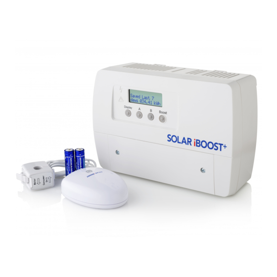
- Page 4 The Solar iBoost+... Check you have received: Solar iBoost+ main unit Wall fixings 2 × AA Batteries Measurement Clamp Sender (with cable & plug) (with socket for measurement clamp)
- Page 5 Solar iBoost+ Quick Start Guide Pre-Installation 1. Read Checks Before Commencing Installation and ensure compliance. 2. Locate a suitably ventilated, flat and vertical surface close to the hot water tank to fix the Solar iBoost+, observing all clearances shown on page 6. Positioning should be convenient for running a cable from a fused spur to the Solar iBoost+ and on to the immersion heater(s).
-
Page 6: Installation
1. Installation Positioning The Solar iBoost+ unit is typically located close to the hot water tank (airing cupboard or similar) and electrically connected between a fused outlet or MCB and the immersion heater. 100mm 100mm 100mm 100mm Minimum clearance is 100mm all around. Do not allow airflow to be obstructed. Fixing the Solar iBoost+ Two hanging brackets and two lower fixing screw points are provided: Rear Hanging Brackets... - Page 7 2. Connecting the Solar iBoost+ The Solar iBoost+ installation must be protected against overcurrent by connecting it via a 16A MCB or 13A fused outlet. Remove the terminal cover, terminals are arranged as follows: 220-240V 50Hz Max 3kW SUPPLY HTR 1 HTR 2 cut-outs for rear cable...
-
Page 8: Wiring Diagrams
Wiring Diagrams Single Immersion Heater Where a single immersion heater is fitted (most common installation) the Solar iBoost+ should be connected as shown. SUPPLY HTR 1 HTR 2 220-240V From 16A MCB or 13A max. 3kW fused outlet Immersion Heater and Thermostat All installations - Test that the thermal cut-out in the immersion heater functions, replace if... - Page 9 Dual Immersion Heater Where two immersion heaters are present, wire the heaters into the Solar iBoost+ as shown below. It is important the upper most heating element in the tank is connected to the HTR1 terminals so that this element receives heating priority.
- Page 10 3. Assembling the Sender and Measurement Clamp The Sender unit has a Measurement Clamp that detects export current when correctly fitted on the live incoming supply cable from the utility meter. The unit sends measurements wirelessly to the Solar iBoost+ unit. Note: The Sender and Solar iBoost+ units are factory paired.
- Page 11 4. Fitting the Measurement Clamp At the utility meter (Caution! not the Generation meter) identify the live cable feed to the property’s consumer unit. Open the Measurement Clamp and remove any plastic packaging. Position the clamp around the cable observing the correct orientation as shown below. Close the Clamp and ensure that the latch is engaged.
-
Page 12: Test The System
5. Test the System These tests are designed to verify that only excess generation is used by the Solar iBoost+. Installers must check that increased energy consumption in the home results in less energy being supplied into the immersion heater. This is indicated in the ‘Heating by Solar’... -
Page 13: User Operation
User Operation Flashes when energy is being diverted to the immersion heater. Symbol is permanently lit when any boost function is on Indicates a problem with the unit when lit (see Trouble Shooting) Display Boost Each press Enables Enables the Provides a Boost moves through programming... - Page 14 Display Cycle The display cycle allows the user to view the recorded energy saving. Each press of the Display button will move through the following sequence Present days energy diverted into the immersion heater Saved Today 03.66 kWh Saved Yesterday Previous days energy diverted into the immersion heater 10.56 kWh Total energy diverted into the immersion heater in the...
-
Page 15: Set Time
Programming The programming function allows: Setting the time and date of the clock Programming of Timed Boosts when grid power is automatically switched on to heat the water. This feature can be used in place of existing timers. The Solar iBoost+ unit is programmed using push buttons A and B. - Page 16 Pairing the Sender Unit The Solar iBoost+ and Sender are supplied uniquely paired and should not require the following operation. However, if the signal becomes lost or a new pairing is required the following procedure should be performed with the sender positioned 1m or more from the Solar iBoost+. Press any button on the Solar iBoost+ to switch on the backlight.
- Page 17 Manual Boost Switches on full power to the immersion heater for the period of time selected. Note that electricity is drawn from the grid if the excess generation is too low. Press any button on the Solar iBoost+ to switch on the backlight. Each press of the Boost button adds 15 minutes to the boost time up to maximum of 2 hours.
-
Page 18: Maximum Power
Troubleshooting - Warnings and Messages The Solar iBoost+ internal diagnostics notify if any fault arises in the system. When a fault is detected the red warning triangle on the front of the unit is illuminated. A message on the display details the specific fault: Batteries are low in the sender unit –... -
Page 19: Further Support
Energy Ltd upon inspection. A valid proof of purchase is required if making a warranty claim. Defective parts must be returned by prepaid post and accompanied by a Returns Authorisation available in advance from Marlec Engineering Company Limited, Rutland House, Trevithick Road, Corby, Northamptonshire, NN17 5XY, England, or to an authorised agent. - Page 20 Maximise the Benefit of Your New Solar iBoost+ We want you to get the most from owning Solar iBoost+ so here’s a few tips to help capture and save more energy using your Solar iBoost+. Reduce or Delay the “ON” Periods of your Current Water Heater Change your heater settings to later in the day, after sundown if possible, as this allows the Solar iBoost+ to preheat water in the tank using the excess PV energy.
Need help?
Do you have a question about the Solar iBoost+ and is the answer not in the manual?
Questions and answers
Since my Solar I-boost was installed in 2014, when I had no battery storage, I have had retrofit Pylon 2 x 3.5kWh batteries and then a new generation system installed with 3 x Fox EP5 5.18kWh batteries - ie a total BESS od 22.54 kWh x 90% = 20+ kWh of usable storage - and so my I-boost is only heating the water when I have SOC 100% = 22.54 kWh stored. But can I not leave my gas HW heating off and simply press the manual boost and use any available battery storage ??