Table of Contents
Advertisement
Quick Links
Download this manual
See also:
Installation Manual
Advertisement
Table of Contents
Troubleshooting

Related Manuals for Furuno FAR-1513


Summary of Contents for Furuno FAR-1513
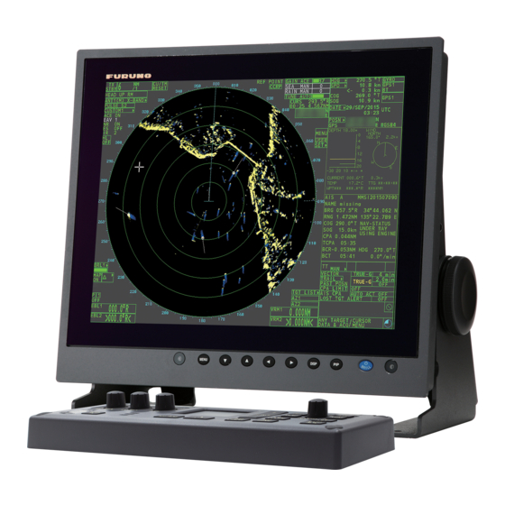
- Page 1 OPERATOR'S MANUAL MARINE RADAR FAR-1513 FAR-1523 FAR-1513-BB FAR-1523-BB FAR-1518 FAR-1528 FAR-1518-BB FAR-1528-BB Model www.furuno.com...
- Page 2 The paper used in this manual is elemental chlorine free. ・FURUNO Authorized Distributor/Dealer 9-52 Ashihara-cho, Nishinomiya, 662-8580, JAPAN A : NOV 2015 Printed in Japan All rights reserved. Pub. No. OME-36380-A (GREG ) FAR-15x3/15x8/BB 0 0 0 1 9 0 8 3 1 1 0...
- Page 3 How to discard a used battery Some FURUNO products have a battery(ies). To see if your product has a battery, see the chapter on Maintenance. Follow the instructions below if a battery is used. Tape the + and - terminals of battery before disposal to prevent fire, heat generation caused by short circuit.
- Page 4 Note: If the antenna unit is installed at a close distance in front of the wheel house, your administration may require halt of transmission within a certain sector of antenna revolution. This is possible. Ask your FURUNO representative or dealer to provide this feature. Transceiver Magnetron...
- Page 5 SAFETY INSTRUCTIONS WARNING WARNING WARNING WARNING ELECTRICAL SHOCK HAZARD. Use the proper fuse. Do not open the equipment. Use of a wrong fuse can result in damage to the equipment or Only qualified personnel should cause fire. work inside the equipment. Keep heater away from equipment.
- Page 6 Refer to official nautical charts for detailed and equipment. Do not remove any label. If a up-to-date information. label is missing or damaged, contact a FURUNO agent or dealer about replacement. WARNING DISPLAY UNIT & To avoid electrical shock, do not PROCESSOR UNIT remove cover.
-
Page 7: Table Of Contents
TABLE OF CONTENTS FOREWORD ........................x SYSTEM CONFIGURATION ..................xii OPERATIONAL OVERVIEW .................1-1 1.1 Controls ........................1-1 1.2 How to Turn the Radar On/Off..................1-3 1.3 How to Adjust the Brilliance..................1-3 1.4 Display Indications......................1-4 1.5 Menu Operations ......................1-6 1.5.1 How to access the main menu ...............1-6 1.5.2 How to operate the menus ................1-6 1.6 How to Use the On-screen Box Menus ..............1-7... - Page 8 TABLE OF CONTENTS 1.27.3 How to restore a user customized echo to the saved settings..... 1-29 1.27.4 How to restore a user customized echo to the factory default settings..1-30 1.28 How to Reject Second-trace Echoes ............... 1-30 1.29 Presentation Modes ....................1-31 1.29.1 How to select an presentation mode............
- Page 9 TABLE OF CONTENTS 1.41.11How to show/hide radar map marks .............1-59 1.41.12How to set the barge marker ................1-59 1.42 Drop Mark.........................1-60 1.42.1 How to inscribe a drop mark.................1-60 1.42.2 How to erase drop marks ................1-60 1.43 How to Adjust Brilliance of On-screen Data .............1-61 1.43.1 How to change color palettes ...............1-61 1.43.2 How to change the echo color..............1-62 1.44 How to Display and Set Up Navigational Data ............1-63...
- Page 10 TABLE OF CONTENTS 3.8 Lost Target ......................... 3-6 3.8.1 How to set the lost target filter................ 3-6 3.8.2 How to enable/disable the lost target alert ............. 3-6 3.9 TT Symbols and Attributes..................3-7 3.9.1 TT symbols..................... 3-7 3.9.2 How to adjust symbol brilliance..............3-7 3.9.3 How to set the symbol color ................
- Page 11 TABLE OF CONTENTS 4.9.3 Past position display orientation ..............4-11 4.9.4 Stabilization in true motion ................4-11 4.10 Lost Target .......................4-12 4.10.1 How to set the lost target filter..............4-12 4.10.2 How to enable/disable the lost target alert ...........4-12 4.11 ROT Setting......................4-13 4.12 AIS Collision Alarm (CPA, TCPA) ................4-13 4.12.1 How to set the CPA and TCPA ranges ............4-13 4.13 How to Associate TT and AIS Targets ..............4-14 4.14 How to View Own Ship Data ..................4-15...
-
Page 12: Foreword
FOREWORD A Word to the Owner of FAR-1513/FAR-1518 Series Congratulations on your choice of the FURUNO FAR-1513/FAR-1518 series of radars. We are confident you will see why FURUNO has become synonymous with quality and reliability. Since 1948, FURUNO Electric Company has enjoyed an enviable reputation for innovative and dependable marine electronics equipment. - Page 13 Program numbers Software Program No. Remarks 0359344-01.** Processor Unit 0359348-01.** Control Unit 0359296-01.** Performance Monitor ** denotes minor modifications. For further software information, please access the following URL: http://www.furuno.com/en/business_product/merchant/product/radar/popup.html...
-
Page 14: System Configuration
SYSTEM CONFIGURATION ANTENNA UNIT FAR-1513(-BB) FAR-1523(-BB) XN12A-RSB-0070-086A XN12A-RSB-0070-087A XN12A-RSB-0073-086A XN12A-RSB-0073-087A XN13A-RSB-0070-086A XN13A-RSB-0070-087A XN13A-RSB-0073-086A XN13A-RSB-0073-087A TRACKBALL CONTROL UNIT Gyrocompass * , AD-10 format CONTROL UNIT RCU-028 RCU-030 Gyrocompass * , IEC61162 format DISPLAY UNIT 12-24 VDC MU-150HD(-CV15)* AIS Transponder 100-230 VAC EPFS (GPS) 1ø, 50-60 Hz... - Page 15 • EPFS meeting the requirements of the IMO resolution MSC.112(73). • SDME meeting the requirements of the IMO resolution MSC.96(72). The radar may be interconnected via HUB-100 to other FURUNO processing units having approved LAN ports. The following sentences cannot be used for installations on SOLAS vessels: BWC, BWR, DBK, GBS, HDG, HDM and TLL.
- Page 16 SYSTEM CONFIGURATION This page is intentionally left blank.
-
Page 17: Operational Overview
OPERATIONAL OVERVIEW Controls Control unit RC-028 Cursor control Range Range Display Control Navigation tools / Menu controls Radar Radar signal signal Alert processing processing Radar Target system Key/Control Description Power switch Press to turn the radar on. Long press to turn the radar off. Shown as in procedures. - Page 18 1. OPERATIONAL OVERVIEW Trackball unit RCU-030 (Option) The optional trackball unit can be used to control most features of this radar. Right Trackball button Left Left - Moves cursor. button button - Highlights an object (target echo, menu item, etc.) Scrollwheel - Selects menu options.
-
Page 19: How To Turn The Radar On/Off
1. OPERATIONAL OVERVIEW How to Turn the Radar On/Off The POWER switch is located at the bottom left corner of the control unit. Open the POWER switch cover and press the switch to turn the radar system on. To turn the system off, press and hold the POWER switch. -
Page 20: Display Indications
1. OPERATIONAL OVERVIEW Display Indications Name Description STBY/TX box Switches between standby and transmit mode. Range box Changes the radar range. CU/TM Reset box Resets display when using Course Up/True Motion presenta- tion mode. REF POINT box Changes the reference point. GAIN box Adjusts the GAIN level. - Page 21 1. OPERATIONAL OVERVIEW Name Description USER SET Loads/saves user specific settings. TGT List Displays the target list; displays the [TARGET LIST] menu. AZ box Activates/deactivates the acquisition zone(s). VRM box Activates/deactivates the VRM. DROP box Displays drop mark data. EBL box Activates/deactivates the EBL.
-
Page 22: Menu Operations
1. OPERATIONAL OVERVIEW Menu Operations 1.5.1 How to access the main menu The main menu can be accessed from the control unit or from the on-screen box. The [MAIN MENU] appears in the text area on the right side of the screen. From the control unit Press the MENU key on the control panel. -
Page 23: How To Use The On-Screen Box Menus
1. OPERATIONAL OVERVIEW How to Use the On-screen Box Menus Some radar functions can be accessed using the on-screen box menus. A “” at the right side of an on-screen box which indicates that there is a box menu. There are two methods for on-screen box menu selection. •... -
Page 24: How To Use The Cursor Menu
1. OPERATIONAL OVERVIEW How to Use the CURSOR Menu Functions that require the use of the cursor, such [CURSOR MENU] as EBL offset and zoom, can be activated directly TARGET DATA & ACQ from the guidance box or from the [CURSOR] TARGET CANCEL menu, either method with the cursor inside the op- TT TGT DATA &... -
Page 25: Cursor Data
1. OPERATIONAL OVERVIEW Cursor Data Cursor data can be shown in latitude and longitude position or the cursor’s X-Y co- ordinates. Place cursor on the [CURSOR DATA] box at the right side of the display then press the left button. The data box shows the cursor information in the upper half and cur- sor location (latitude/longitude) is shown in the lower half. -
Page 26: How To Set Up Function Keys
1. OPERATIONAL OVERVIEW How to Set Up Function Keys Some menu functions and menus can be assigned to a function key. This allows one- touch access to the assigned function or menu. To activate an assigned function, press the corresponding function key (F1, F2 or F3). The function keys are preset with the following functions: F1: A/C RAIN, F2: A/C SEA, F3: ACE (Gain). -
Page 27: How To Customize Operation
2. Select [HDG SOURCE], then push the ADJUST knob. 3. Select [AD-10] or [SERIAL] as appropriate, then push the ADJUST knob. This refers to the type of connection, [AD-10] is for AD-10 format (FURUNO orig- inal) connection, [SERIAL] is for serial connections. -
Page 28: How To Set Own Ship's Speed
1. OPERATIONAL OVERVIEW 1.12 How to Set Own Ship’s Speed The TT and azimuth stabilized presentation modes require own ship speed input and compass signal. The speed can be entered from a log (STW, SOG) or GPS (SOG) or manually on the menu. Note: Where the own ship speed exceeds 99.9kn, the displayed speed is "99.9kn". -
Page 29: Manual Speed Input
1. OPERATIONAL OVERVIEW 1.12.2 Manual speed input If the speed log is not working, enter speed manually as below. In this case the speed data type is shown as "MANUAL" and is speed thru water (STW). Manual speed input is not available on the IMO radar when the AIS feature is active. 1. -
Page 30: User Settings
1. OPERATIONAL OVERVIEW 1.14 User Settings The user functions shown in the table below can be reset to their default settings by enabling the [PILOT SETTING] option in the [USER SET] menu. Functions not shown in the table below maintain their previous setting. The unit can store two separate user settings, for the functions listed below, in the in- ternal memory. -
Page 31: How To Reset The User Settings
1. OPERATIONAL OVERVIEW Function Setting(s) Menu/On-screen box Continued from previous page Vector mode [REL] [VECTOR] box Vector time [6 MIN] [OFF] [AZ1] box [OFF] [AZ2] box [TT TARGET] [TT SELECT] TT acquisition mode [MAN50] AIS display [DISP ALL] [AIS] box [MAIN MENU] ... -
Page 32: How To Start/Stop Transmission
1. OPERATIONAL OVERVIEW 1.15 How to Start/Stop Transmission The radar is ready to transmit when the message "STBY" appears. Transmission can be started using one of the following procedures: • Using the control unit: Press the STBY/TX key. • Using the on-screen box: Select the [STBY/TX] box on the screen, then press the left button. -
Page 33: How To Tune The Receiver
1. OPERATIONAL OVERVIEW 1.16 How to Tune the Receiver 1.16.1 How to select the tuning method 1. Select the [TUNE] box at the top of the screen to change the tuning method. The tuning box is displayed as "TUNE AUTO" or "TUNE MAN", depending on the cur- rently selected tuning method. -
Page 34: How To Select A Pulselength
1.17 How to Select a Pulselength The pulselength in use appears at the upper-left position of the screen using the indi- cations shown in the table below. FAR-1518/FAR-1528 FAR-1513/FAR-1523 (PULSE) indication (PULSE) indication S1 (short pulse 1) S (short pulse) -
Page 35: How To Adjust Sensitivity
1. OPERATIONAL OVERVIEW 1.18 How to Adjust Sensitivity The gain control adjusts the sensitivity of the receiver. The proper setting is such that the background noise is just visible on the screen. If you set up for too little sensitivity, weak echoes may be missed. On the other hand excessive sensitivity yields too much background noise;... -
Page 36: How To Fine-Tune Sea Clutter Reduction
1. OPERATIONAL OVERVIEW 1.19.2 How to fine-tune sea clutter reduction Auto A/C SEA allows for fine tuning of the A/C SEA circuit, within ±20 dB. Accordingly, with the bar reading set to 50, gain is not lowered to minimum as with manual A/C SEA on close-in ranges. -
Page 37: How To Reduce Rain Clutter
1. OPERATIONAL OVERVIEW How to reduce sea clutter manually from the on-screen box 1. Select [SEA MAN], following the procedure in paragraph 1.19.1. 2. Place the arrow in the A/C SEA level indicator at the top of the display. 3. While observing the A/C SEA level indicator, rotate the ADJUST knob clockwise to increase the A/C SEA or counter-clockwise to decrease it. - Page 38 1. OPERATIONAL OVERVIEW How to fine-tune sea clutter reduction from the on-screen box 1. Select the [RAIN] indication at the top-right of the screen, then press the left but- ton to select [RAIN MAN]. Level bar Place arrow inside window to adjust A/C RAIN.
-
Page 39: Interference Rejector
1. OPERATIONAL OVERVIEW 1.21 Interference Rejector Mutual radar interference can occur in the vicinity of another shipborne radar operat- ing in the same frequency band. It is seen on the screen as a number of bright spikes either in irregular patterns or in the form of usually curved spoke-like dotted lines ex- tending from the center to the edge of the picture. -
Page 40: Echo Averaging
1. OPERATIONAL OVERVIEW 1.23 Echo Averaging The echo averaging feature effectively reduces sea clutter. Echoes received from sta- ble targets such as ships appear on the screen at almost the same position every ro- tation of the antenna. On the other hand, unstable echoes such as sea clutter appear at random positions. -
Page 41: Automatic Clutter Elimination (Ace) Function
1. OPERATIONAL OVERVIEW 1.24 Automatic Clutter Elimination (ACE) Function This radar has the Automatic Clutter Elimination (ACE) function. This function detects sea and rain clutter from received echoes’ range and bearing trend and automatically reduces sea and rain clutter according to the Automatic Clutter Elimination (ACE) threshold setting. -
Page 42: How To Suppress False Echoes
1. OPERATIONAL OVERVIEW 1.24.4 How to suppress false echoes The echo signals can appear on the screen at positions where there is no target or disappear when there are targets (see section 2.2). You can suppress the false echoes. 1. Open the [MAIN MENU]. 2. -
Page 43: How To Preset Controls For A Specific Navigation Purpose
1. OPERATIONAL OVERVIEW 2. Select [ECHO], then push the ADJUST knob. 3. Select [WIPER], then push the ADJUST knob. 4. Rotate the ADJUST knob to cycle through and select the desired setting. The op- tions, in order, are: OFF 1 2 OFF... With the desired setting selected, push the ADJUST knob. -
Page 44: How To Select A Customized Echo
ACE GAIN PULSE 0.5NM (FAR-1518/1528) 0.75NM 1.5NM 12NM 24NM PULSE 1.5NM (FAR-1513/1523) CONDITION NEAR CURVE Set at installation. HEIGHT LEVEL ECHO 1.27.1 How to select a customized echo Left-click [CUSTOMIZE ECHO] box at the top left of the screen to cycle through the options and select a customized echo option. -
Page 45: How To Edit A Customized Echo
1. OPERATIONAL OVERVIEW 1.27.2 How to edit a customized echo 1. Select a customize echo option to edit (see paragraph 1.27.1). 2. Select the [CUSTOMIZE ECHO] box, then press the right button to display the [CUSTOMIZE ECHO] menu. 3. Set the items below referring to the sections shown. •... -
Page 46: How To Restore A User Customized Echo To The Factory Default Settings
1. OPERATIONAL OVERVIEW 1.27.4 How to restore a user customized echo to the factory default settings You can restore customized echo options to their factory default (see the table on page 1-28). 1. Select the [CUSTOMIZE ECHO] box, then press the right button to display the [CUSTOMIZE ECHO] menu. -
Page 47: Presentation Modes
1. OPERATIONAL OVERVIEW 1.29 Presentation Modes This radar has the following presentation modes available: Relative Motion (RM) HEAD UP : Not stabilized STAB HEAD UP : Head-up with compass bearing scale (True Bearing) where the bearing scale rotates with the compass reading. COURSE UP : Compass-stabilized relative to ship’s orientation at the time of se- lecting COURSE UP. - Page 48 1. OPERATIONAL OVERVIEW COURSE UP mode The radar picture is stabilized and displayed with the North marker Heading line currently selected course at the top of the screen. When you change the heading, the heading line moves with the course selected. If you select a new course, select the course up mode again to display the new course at the top of the display.
-
Page 49: How To Select A Range Scale
1. OPERATIONAL OVERVIEW STERN UP mode The STERN UP mode rotates the HEAD UP mode picture, relative and true bearings and display graphics 180°. This mode is useful on dual-radar tugboats when backing up; one ra- dar shows HEAD UP and another shows STERN UP. -
Page 50: How To Measure Range
1. OPERATIONAL OVERVIEW 1.31 How to Measure Range The range to a target can be measured three ways: with the fixed range rings, with the cursor, or with the VRM. Use the fixed range rings to get an estimate of the range to a target. The rings are the concentric solid circles on the display. -
Page 51: How To Set The Vrm Unit Of Measurement (Non-Imo Type Only)
1. OPERATIONAL OVERVIEW Using the VRM key 1. Press the VRM key to display the VRM boxes. Press the VRM key again to switch between active VRMs. The currently active VRM marker is displayed as shown in the figure on the previous page. 2. -
Page 52: How To Show Ttg To Vrm
1. OPERATIONAL OVERVIEW 1.31.4 How to show TTG to VRM TTG (Time To Go) to a selected VRM can be displayed as follows: 1. Open the [MAIN MENU]. 2. Select [NAVTOOL], then push the ADJUST knob. 3. Select [EBL•VRM•CURSOR], then push the ADJUST knob. 4. -
Page 53: Methods To Measure Bearing
1. OPERATIONAL OVERVIEW 1.32.1 Methods to measure bearing There are two methods for measuring bearing, using the EBL key and on-screen menu box operation. Using the EBL key 1. Press the EBL key to display the EBL boxes. Press the key again to change be- tween EBLs. -
Page 54: True Or Relative Bearing
1. OPERATIONAL OVERVIEW 1.32.2 True or relative bearing The EBL readout is affixed by "R" (relative) if it is relative to own ship's heading, "T" (true) if it is referenced to the north. True or relative indication is available regardless of presentation mode. -
Page 55: How To Assess Risk Of Collision Using The Offset Ebl
1. OPERATIONAL OVERVIEW 1.33.1 How to assess risk of collision using the offset EBL There are two methods for assessing risk collision. You can use the control unit or the [CURSOR] menu. Using the control unit (RCU-028) Note: The [EBL OFFSET] function must be assigned to a function key (F1, F2 or F3) for this method. -
Page 56: How To Set The Origin Point Reference For Ebl Offset
1. OPERATIONAL OVERVIEW 1.33.2 How to set the origin point reference for EBL OFFSET The origin point of the offset EBL can be ground stabilized (geographically fixed), north stabilized (true) or referenced to own ship’s heading (relative). 1. Open the [MAIN MENU]. 2. - Page 57 1. OPERATIONAL OVERVIEW 4. With the cursor in the operational display area, press the ADJUST knob. EBL1 moves to the cursor location. 5. Place the offset EBL on the target of interest (Target 1), then push the ADJUST knob. 6. Press the right button to deactivate the [EBL OFFSET] mode. The red surround on the cursor disappears.
- Page 58 1. OPERATIONAL OVERVIEW How to reset the EBL origin to the center of the screen 1. Place the cursor on the EBL1 box, then press the left button. EBL1 is now active. 2. Place the cursor inside the operational display area, then press the right button. The [CURSOR] context menu appears.
-
Page 59: How To Off-Center The Display
1. OPERATIONAL OVERVIEW 1.35 How to Off-Center the Display Own ship position, or sweep origin, can be displaced to expand the view field without switching to a larger range scale. The sweep origin can be off-centered to the cursor position, but not more than 75% of the range in use; if the cursor is set beyond 75% of the range scale, the sweep origin will be off-centered to the point of 75% of the limit. -
Page 60: Target Trails
1. OPERATIONAL OVERVIEW 1.36 Target Trails The trails of the radar echoes of targets can be displayed in the form of synthetic afterglow. Target trails are shown either relative or true and can be sea or ground stabi- lized. True motion trails require a compass signal, and position and speed data. -
Page 61: Trail Time
1. OPERATIONAL OVERVIEW 1.36.2 Trail time Trail time is the interval at which the trail is plotted on-screen. You can change the trail time as follows: Using the control unit (RCU-028) 1. Place the cursor on the trail time setting inside the [TRAIL] box at the bottom-right corner of the screen, then press the left button. -
Page 62: Trail Level
1. OPERATIONAL OVERVIEW 1.36.4 Trail level The level, or intensity, of the afterglow that extends from radar targets can be selected as below. 1. Select the [TRAIL] box at the bottom-right corner of the screen, then press the right button to display the [TRAIL MENU]. 2. -
Page 63: How To Prevent Sea Clutter In True Trails
1. OPERATIONAL OVERVIEW 1.36.9 How to prevent sea clutter in true trails You can prevent the display of sea clutter in true trails about your ship to clear the ra- dar picture. Your ship's trails can also be shown or hidden. 1. -
Page 64: How To Activate/Deactivate The Target Analyzer
1. OPERATIONAL OVERVIEW Moderate echo adjustment Maximum echo adjustment (Target analyzer on, EAV on, hatching off) (Target analyzer on, EAV on, hatching on) Echoes are colored, surface reflections and Echoes are colored, surface reflections are rain are filtered. filtered, rain is displayed in gray colored hatching. -
Page 65: Target Alarm
1. OPERATIONAL OVERVIEW 1.38 Target Alarm The target alarm serves to alert the navigator to targets (ships, landmasses, etc.) en- tering a specific area, with audiovisual alerts. The target alarm zone has a fixed width of CAUTION CAUTION 0.5 nm in the radial direction (depth) and is adjustable from 3.0 to 6.0 nm (target The alarm should not be relied upon as the alarm zone 1) and any distance (target... -
Page 66: How To Mute The Target Alarm
1. OPERATIONAL OVERVIEW 1.38.2 How to mute the target alarm A target in the target alarm zone produces both visual (flashing) and audible (beep) alarms. To silence the audio alarm select the appropriate target alarm box then press the left button. The target alarm box indication shows "ALR MUTE". This will deac- tivate the audio alarm but will not stop the flashing of the offending target. -
Page 67: Pi (Parallel Index) Lines
1. OPERATIONAL OVERVIEW 1.39 PI (Parallel Index) Lines PI lines are useful for keeping a constant distance be- tween own ship and a coastline or a partner ship when navigating. Up to six sets of PI lines are available de- pending on the maximum number of PI lines selected on the menu. -
Page 68: How To Change The Pi Line Bearing Reference
1. OPERATIONAL OVERVIEW 1.39.3 How to change the PI line bearing reference PI line bearing reference can be relative to own ship’s heading (Relative) or refer- enced to North (True) as below. Note: This function is not available with IMO type radars in this series. The setting is fixed to [TRUE]. -
Page 69: How To Change Pi Line Length
1. OPERATIONAL OVERVIEW 1.39.6 How to change PI line length You can change the length of the PI lines. This function is only available when [SET ALL PI LINE] in the [PI LINE] menu is set to [1]. If not already displayed, you can show PI lines for which you wish to change the length by referring to paragraph 1.39.1. -
Page 70: Zoom
1. OPERATIONAL OVERVIEW 1.40 Zoom The zoom function enlarges an area of interest as large as twice the normal viewing size, in the [INFORMATION BOX]. Zoom can be selected using the control unit or from a preset function key (see section 1.9 for how to assign functions to the function keys). Zoom is not available when the [INFORMATION BOX] setting for [TARGET DATA] is [LARGE]. -
Page 71: How To Use Marks
1. OPERATIONAL OVERVIEW 1.41 How to Use Marks Select the [MARK] box at the bottom of the screen then press the right button to open the [MARK] context [MARK MENU] menu. ORIGIN MARK STAB GND / STAB SEA Marks can be entered at any location inside the opera- MARK KIND tional display area, however, no mark can be entered at ORIGIN MARK(No.) /... -
Page 72: How To Select The Mark Inscription Position
1. OPERATIONAL OVERVIEW 1.41.2 How to select the mark inscription position You can select the location at which the marker is inscribed from the following: Location Description [CURSOR] You can select the location using the Touchpad. [OWN SHIP] Marker is placed at own ship position. [L/L] Marker is placed at the co-ordinates selected. -
Page 73: How To Inscribe Marks
1. OPERATIONAL OVERVIEW 1.41.4 How to inscribe marks You can inscribe marks anywhere inside the operational display area, however, marks cannot be inscribed in the same location as a menu box. 1. Select the [MARK] box. The [MARK] box is now highlighted. 2. -
Page 74: How To Hide The Heading Line Marker
1. OPERATIONAL OVERVIEW 1.41.7 How to hide the heading line marker The heading line is a line from the own ship position to the outer edge of the radar dis- play area and appears at zero degrees on the bearing scale in HEAD UP mode. The orientation of the line changes the orientation depending on the ship orientation in NORTH UP and True Motion modes. -
Page 75: 10How To Use The Ins Marker
1. OPERATIONAL OVERVIEW 1.41.10 How to use the INS marker You can receive predicted position data by connecting this radar to an INS. 1. Open the [MAIN MENU]. 2. Select [MARK], then push the ADJUST knob. 3. Select [INS MARK], then push the ADJUST knob. 4. -
Page 76: Drop Mark
1. OPERATIONAL OVERVIEW 1.42 Drop Mark The operator can inscribe a drop mark at a selected location to find the range and bearing from own ship to the mark. This can be useful for marking a point to avoid while navigating to a destination. To active the drop mark feature, do the following: 1. -
Page 77: How To Adjust Brilliance Of On-Screen Data
1. OPERATIONAL OVERVIEW 1.43 How to Adjust Brilliance of On-screen Data On-screen markers and alphanumeric readout brilliance can be adjusted using the fol- lowing procedure: 1. Place the cursor on the [BRILL] box at the right of the screen, then press the right button. -
Page 78: How To Change The Echo Color
1. OPERATIONAL OVERVIEW How to assign/change the brilliance presets 1. Place the cursor on the BRL indication inside the [BRILL] box. 2. Press the left button to cycle through the pre- Place cursor here, sets. There are four available: [BRL1], [BRL2], then press the left [BRL3] and [BRL4]. -
Page 79: How To Display And Set Up Navigational Data
1. OPERATIONAL OVERVIEW 1.44 How to Display and Set Up Navigational Data Wind, depth, ocean current, water temperature, date and time and waypoint data can be displayed on this radar, however appropriate sensors are required. 1.44.1 How to set up the navigational data 1. -
Page 80: How To Use The Information Box
1. OPERATIONAL OVERVIEW 1.45 How to Use the Information Box The information box shows target data, navigational data and zoomed areas of the ra- dar display. To set up the information box, do the following: 1. Open the [MAIN MENU]. [INFORMATION BOX] 2. -
Page 81: Interswitch
1. OPERATIONAL OVERVIEW 1.46 Interswitch The interswitch of this ra- Antenna box dar uses an Ethernet to ANT1 (or ANT2): indicates transfer video and con- antenna selected (M) or (S): indicates antenna is trol signals. A digital sig- (M)aster or (S)lave nal transfers the video X-Band: indicates the antenna and control signals. - Page 82 1. OPERATIONAL OVERVIEW Antenna selection considerations • An antenna unit cannot be controlled from multiple display units. Select one Master display unit for one antenna unit. If two antenna units are set as masters, the display last-set as master becomes the master and all other displays are automatically changed to slave.
-
Page 83: Performance Monitor
1. OPERATIONAL OVERVIEW Radar Functions Control Master Display Option Slave Display Option A/C SEA Dependent Desired value can be set Cannot control Control A/C RAIN Automatic Clutter Elimination (ACE) Gain Echo stretch Echo averaging Picture setting (Customize echo) STBY/TX Tuning Reference Point TT LOST warning Common... -
Page 84: How To Check The Radar's Performance
1. OPERATIONAL OVERVIEW Adjustable Setting at PM Setting while PM Setting at PM deactivation activation is active Setting before PM activation. Setting before PM activation. NOISE REJECT Setting before PM activation. VIDEO CONTRAST Setting before PM activation. PULSE LONG Setting before PM activation. 2ND ECHO REJ Setting at PM deactivation. -
Page 85: How To Change The Reference Position
1. OPERATIONAL OVERVIEW 1.48 How to Change the Reference Position The reference position for measurements (range, bearing, etc.) and markers (heading line, stern mark, etc.) can be the radar antenna position ([ANT]) or the consistent com- mon reference point ([CCRP]). The reference position is a location on own ship to which all horizontal measurements, for example range, bearing, relative course, relative speed, closest point of approach (CPA) or time to closest point of approach (TCPA), are normally referenced. -
Page 86: Anchor Watch
1. OPERATIONAL OVERVIEW Reference point Category Item CCRP CPA, TCPA Calculated with an- Calculated with tenna position at CCRP at center. center. BCR, BCT Calculated from bow position. Own ship data Heading Data is taken from respective sensors, re- gardless of reference point selected. Speed Course over ground Speed over ground... -
Page 87: How To Interpret The Alert Box
1. OPERATIONAL OVERVIEW 1.50 How to Interpret the ALERT Box When an alert condition is found, the applicable alert message appears in the [ALERT] box. A buzzer sounds for alarm and warning alerts. The [ALERT] box is composed of three lines of information, and two icons, as shown below. Alert title Buzzer silence icon... -
Page 88: Alert List
1. OPERATIONAL OVERVIEW 1.50.2 Alert list The alert list displays the names of violated alerts, including the time and date violated. Up to 100 alerts are stored in the internal memory. Unacknowledged alarms are dis- played first in the list (in red text), in the order in which they appear in the [ALERT] box. Unacknowledged warnings are displayed in the list (in yellow-orange text), in the order in which they appear in the [ALERT] box. -
Page 89: Alert Icons And Their Meanings
1. OPERATIONAL OVERVIEW 1.50.3 Alert icons and their meanings Icon Status Visual indication Audible alert Active - unacknowledged alarm Red, flashing 3 short, audible alerts repeated every 7 seconds. Active - silenced alarm Red, flashing Silent Active - acknowledged alarm Silent Active - responsibility Silent... -
Page 90: How To Select A Display Mode (For Non-Imo Types Only)
1. OPERATIONAL OVERVIEW 1.51 How to Select a Display Mode (For Non-IMO types Only) Non-IMO type radars of this series have two display modes available: • Standard display mode: The operational display area, box functions, data display, etc. are shown in a standard (IMO compliant) manner. •... -
Page 91: How To Manage Sd-Card Data
1. OPERATIONAL OVERVIEW 1.52 How to Manage SD-Card Data The following data can be stored on a SD-Card: marks, lines, user settings, installation settings, own track, alert history and some alert logs (for example, the alert log). 1.52.1 How to access the SD-Card menu Note: This operation is only available when a SD-Card is inserted. - Page 92 1. OPERATIONAL OVERVIEW This page is intentionally left blank. 1-76...
-
Page 93: Radar Observation
RADAR OBSERVATION General 2.1.1 Minimum and maximum ranges Minimum range The minimum range is defined by the shortest distance at which, using a scale of 1.5 or 0.75 nm, a target having an echoing area of 10 m is still shown separate from the point representing the antenna position. - Page 94 This is determined by pulselength only. Practically, a 0.08 microsecond pulse offers the discrimination better than 40 m as do so with all FURUNO radars. Test targets for determining the range and bearing resolution are radar reflectors...
-
Page 95: False Echoes
2. RADAR OBSERVATION Bearing accuracy One of the most important features of the radar is how accurately the bearing of a tar- get can be measured. The accuracy of bearing measurement basically depends on the narrowness of the radar beam. However, the bearing is usually taken relative to the ship’s heading, and thus, proper adjustment of the heading line at installation is an important factor in ensuring bearing accuracy. -
Page 96: Sidelobe Echoes
2. RADAR OBSERVATION Sidelobe echoes Every time the radar pulse is transmitted, some radiation escapes on each side of the beam, called “sidelobes”. If a target exists where it can be detected by the side lobes as well as the main lobe, the side echoes may be represented on both sides of the true echo at the same range. -
Page 97: Shadow Sectors
2. RADAR OBSERVATION Shadow sectors Funnels, stacks, masts, or derricks in the path of the antenna block the radar beam. If the angle subtended at the antenna is more than a few degrees, a non-detecting sec- tor may be produced. Within this sector targets can not be detected. Wharf and its echo Radar position Radar position... -
Page 98: Sart (Search And Rescue Transponder)
2. RADAR OBSERVATION SART (Search and Rescue Transponder) 2.3.1 SART description A Search and Rescue Transponder (SART) can be triggered by any X-Band (3 cm) radar within a range of approximately 8 nm. Each radar pulse received causes it to transmit a response which is swept repetitively across the complete radar frequency band. -
Page 99: General Remarks On Receiving Sarts
2. RADAR OBSERVATION Setting Changed to Range 12 NM Pulselength Long Echo Stretch Noise Rejector Echo Averaging Interference Rejector Performance Monitor A/C RAIN 5. Close the menu. The indication "SART" appears at the bottom of the alert box, in yellow text, when this feature is active. -
Page 100: Racon
2. RADAR OBSERVATION RACON A RACON is a radar beacon that emits radar receivable signals in the radar frequency spectrum (X- or S-band). There are several signal formats; in general, the RACON sig- nal appears on the radar screen as a rectangular echo originating at a point just be- yond the position of the radar beacon. -
Page 101: Target Tracking (Tt)
TARGET TRACKING (TT) Precautions for Target Tracking Usage WARNIN WARNING CAUTION CAUTION The plotting accuracy and response of No one navigational aid should be relied this TT meets IMO standards. Tracking upon for the safety of vessel and crew. accuracy is affected by the following: The navigator has the responsibility to check all aids available to confirm Tracking accuracy is affected by course... -
Page 102: Tt Controls
3. TARGET TRACKING (TT) TT Controls The control unit has two keys that are used in the target tracking mode. The keys are indicated in the figure below. Manual target acquisition Cancel target • TGT ACQ: Acquires the selected echo as a target. •... -
Page 103: How To Acquire And Track Targets
3. TARGET TRACKING (TT) How to Acquire and Track Targets Place the cursor on the TT acquisition mode indicator, then press the left button. The indication changes, depending on the TT mode selected (See section 3.4). The table below shows the indication changes based on mode selection. TT mode selected Indication change "OFF"... -
Page 104: How To Enter Own Ship Speed
3. TARGET TRACKING (TT) How to Enter Own Ship Speed The TT requires own ship's speed and heading data. The speed can be STW, SOG or echo-referenced speed (based on 3 max. stationary objects). Manual input is also possible. For automatic or manual input, see section 1.12. For echo-referenced speed input follow the procedure below. -
Page 105: How To Cancel Target Tracking
3. TARGET TRACKING (TT) How to cancel echo-referenced speed input 1. Open the [MAIN MENU]. 2. Select [SHIP SPEED MENU], then push the ADJUST knob. 3. Select [SHIP SPEED], then push the ADJUST knob. 4. Select any option, other than [REF] or [MANUAL], then push the ADJUST knob. 5. -
Page 106: Lost Target
3. TARGET TRACKING (TT) Lost Target Targets not detected in five consecutive scans become “lost targets”. A lost target is shown in the display with a flashing red "X". Flashing stops after lost target alert is ac- knowledged. If you are in an area where tracked targets are lost frequently, you may want to disable the lost target alert against tracked targets, by maximum range or minimum speed. -
Page 107: Tt Symbols And Attributes
3. TARGET TRACKING (TT) TT Symbols and Attributes 3.9.1 TT symbols Item Symbol Status Remarks Automatically Initial stage Broken circle around an echo to indicate acquired target that the target is under acquisition and initial symbols shown. stage of tracking, before steady-state tracking. -
Page 108: How To Display/Remove Target Data
3. TARGET TRACKING (TT) 3.9.3 How to set the symbol color 1. Open the [MAIN MENU]. 2. Select [TT•AIS], then push the ADJUST knob. 3. Select [TT•AIS SYMBOL], then push the ADJUST knob. 4. Select [SYMBOL COLOR], then push the ADJUST knob. The settings can now be adjusted. -
Page 109: How To Remove Target Data
3. TARGET TRACKING (TT) 3.10.2 How to remove target data Place the cursor on a desired tracked target and press the TGT CANCEL key. The select target’s data is removed from the data display area. 3.10.3 How to display, hide and sort the target list The target list provides a comprehensive data display of all TT (and AIS) targets being tracked. -
Page 110: Vector Modes
3. TARGET TRACKING (TT) 3.11 Vector Modes Target vectors can be displayed relative to own ship’s heading (Relative) or North (True). Note: IMO recommends the use of true vector mode in sea stabilization or relative vector mode for collision avoidance. To change the vector mode, do the following: Place the cursor on the vector reference indication in the [Vector] box, then press the left button. - Page 111 3. TARGET TRACKING (TT) Ground stabilization and sea stabilization Target vectors can be ground stabilized or sea stabilized in the True Motion mode. To select speed over the ground or speed through the water data, open the page from the menu.
-
Page 112: How To Change The Vector Length (Time)
3. TARGET TRACKING (TT) 3.11.2 How to change the vector length (time) The vector time provides an estimation of the target’s vector and can be adjusted as follows: Place the cursor on the vector time indication in the [Vector] box, then press the left button. -
Page 113: Set And Drift
3. TARGET TRACKING (TT) 3.13 Set and Drift Set, the direction in which a water current flows, can be manually entered in 0.1-de- gree steps. Drift, also known as “Rate”, or the speed of the current, can also be en- tered manually in 0.1-knot steps. -
Page 114: Collision Alarm (Cpa, Tcpa)
3. TARGET TRACKING (TT) 3.14 Collision Alarm (CPA, TCPA) This radar calculates CPA and TCPA by using own ship and relative target positions. The TT continuously monitors the pre- CAUTION dicted range at the Closest Point of Ap- proach (CPA) and predicted time to CPA/TCPA Alarm CPA (TCPA) of each TT. -
Page 115: Acquisition Zone
3. TARGET TRACKING (TT) 3.15 Acquisition Zone The acquisition zone functions both to alert you targets in a specific area and acts as an automatic acquisition area when automatic target acquisition is active. Any targets entering the zone will be automatically acquired. When a target enters an acquisition zone, the buzzer sounds and the indication "TT NEW TARGET"... -
Page 116: How To Set A Polygon Acquisition Zone (Az2)
3. TARGET TRACKING (TT) 3.15.2 How to set a polygon acquisition zone (AZ2) The No. 2 acquisition zone can be set anywhere when the No. 1 zone is already in use. Polygon zones must have at least three points. To set a polygon shaped acquisition zone: 1. -
Page 117: How To Change The Acquisition Zone Reference
3. TARGET TRACKING (TT) 3.15.5 How to change the acquisition zone reference The acquisition zone can be referenced to heading or North using the following pro- cedure: 1. Open the [MAIN MENU]. 2. Select [TT•AIS], then push the ADJUST knob. 3. -
Page 118: Tt System Messages
3. TARGET TRACKING (TT) 3.16 TT System Messages There are four main reasons the TT may trigger the audio and visual alerts: • Collision alarm • Acquisition zone alert • Lost target alert • Target capacity To acknowledge the alert, press the ALERT ACK key on the control unit, or select the [ALERT] box with the Touchpad then press the left button to acknowledge the alert and silence the buzzer. -
Page 119: Tt Simulation Mode
3. TARGET TRACKING (TT) 3.17 TT Simulation Mode You can simulate the risk of a collision by using the TT simulation mode. The test can be terminated at any time by pressing the STBY/TX key. 1. Open the [MAIN MENU]. 2. -
Page 120: Criteria For Tracking Target Selection
3.18 Criteria for Tracking Target Selection The FURUNO TT video processor detects targets in midst of noise and discriminates radar echoes on the basis of their size. Target whose echo measurements are greater than those of the largest ship in range or tangential extent are usually land and are displayed only as normal radar video. -
Page 121: Factors Affecting Tt Functions
Qualitative description of tracking error The FURUNO TT's accuracy complies with or exceed IMO standards. Own ship maneuvers For slow turns there is no effect. For very high turning rates (greater than 150°/minute, depending on gyro), there is some influence on all tracked targets that lasts for a min- ute or two then all tracked targets revert to full accuracy. - Page 122 3. TARGET TRACKING (TT) Non-synchronous emissions No effect. Second trace echoes When the radar beam is super refracted, strong echoes may be received at such long ranges that they appear on a different timebase sweep than the transmitted pulse. This gives an incorrect range indication. Second and third trace echoes can be tracked if they are consistent enough to meet acquisition and tracking criteria but target course and speed data will be in error.
-
Page 123: Ais Operation
AIS OPERATION An AIS transponder can be connected to this radar to overlay AIS targets on the radar display. The radar can store up to 1,000 AIS targets in its storage buffer. When this buffer becomes full of AIS targets, the Alert 190 "TARGET CAPACITY (AIS CAPACI- TY FULL)"... -
Page 124: Controls For Ais
4. AIS OPERATION There can be several hundreds or several thousands of AIS targets, and of those only a few will be significant for your ship. To remove unnecessary AIS targets from the radar display, the feature “activated and sleeping AIS targets” is available. Initially any new AIS target received by an AIS transponder is not activated (=“sleeping”). -
Page 125: Ais Symbols And Their Meanings
4. AIS OPERATION AIS Symbols and Their Meanings When the AIS is active, AIS targets are marked with the appropriate AIS symbol, as shown in the table below. SYMBOL STATUS REMARKS Activated All AIS symbols shown with thick line. target Color is selectable from menu. - Page 126 4. AIS OPERATION AIS Physical AIS Virtual Meaning AtoN Symbol AtoN Symbol Basic shape RACON Emergency wreck mark North cardinal mark East cardinal mark South cardinal mark West cardinal mark Port hand mark Starboard hand mark Isolated danger Safe water Special mark Off position (Displayed with yellow line and yellow text)
-
Page 127: How To Use The Ais Display Filter
4. AIS OPERATION How to Use the AIS Display Filter If there are too many AIS targets on the screen you may wish to remove unnecessary ones. You can remove sleeping targets class A/B by distance from own ship, speed and class. -
Page 128: How To Enable/Disable The Ais Auto Activate Function
4. AIS OPERATION 4.4.2 How to enable/disable the AIS auto activate function Use the [CPA AUTO ACTIVATE] box at the bottom right corner to enable or disable the AIS auto activate function. Select the AIS CPA box, then press the left button to cycle through AIS display modes. -
Page 129: How To Sleep Ais Targets
4. AIS OPERATION How to Sleep AIS Targets 4.5.1 How to sleep individual AIS targets You can “sleep” an AIS target as below when the screen becomes filled with targets, which might prevent important radar and AIS displays from being identified. Note: Targets that have been activated automatically and dangerous targets cannot be “slept”. - Page 130 4. AIS OPERATION Status Meaning Continued from previous page. AIS SART (No use) AIS SART TEST 5. Select [ETA], then push the ADJUST knob. 6. Using the ADJUST knob, set the estimated day of the month to arrive, then push the ADJUST knob.
-
Page 131: Target Data
4. AIS OPERATION Target Data You can display an AIS target’s data by selecting it on the display, when the AIS func- tion is set for [AIS DISP FILT]. 4.7.1 How to display target data in the data display area Place the cursor on a desired AIS target and press the TGT ACQ key. -
Page 132: How To Change Ais Symbol Attributes
4. AIS OPERATION How to Change AIS Symbol Attributes The AIS symbol’s brilliance, size and color can be changed. 4.8.1 How to adjust the AIS symbol brilliance 1. Place the cursor on the [BRILL] box, then press the right button. The [BRILL] menu appears. -
Page 133: Past Position Display
4. AIS OPERATION Past Position Display The past position display shows equally time-spaced dots marking past positions of activated AIS targets. A new dot is added at preset time intervals until the preset num- ber is reached. If a target changes its speed, the spacing will be uneven. If it changes course, its plotted course will not be a straight line. -
Page 134: Lost Target
4. AIS OPERATION 4.10 Lost Target A target is declared a lost target when it fails to produce data for six minutes or five reporting intervals, whichever is the shorter. When this occurs, the target is marked with the (flashing) lost target symbol and the message "LOST" appears in the Alert Box. -
Page 135: Rot Setting
4. AIS OPERATION 4.11 ROT Setting You can set the lower limit of the ROT (Rate Of Turn) at which the heading line on target symbols will point in direction which the vessel is turning. Ship turning to starboard ROT display 1. -
Page 136: How To Associate Tt And Ais Targets
4. AIS OPERATION 2. Press the left button, or rotate the ADJUST knob, to adjust the settings as re- quired. The settings options are outlined in the table below. Indication Settings options Left button 0.5, 1, 1.5, 2, 3, 4, 5, 6 (nm) ADJUST 0.1-20 (nm), 0-10 nm in 0.1 nm increments, 10 nm incre- ments thereafter... -
Page 137: How To View Own Ship Data
4. AIS OPERATION 7. Referring to the table below, set the association criteria. Rotate the ADJUST knob to adjust the value, push the ADJUST knob to move to the next digit. [GAP]: Range in bearing direction between AIS target and tracked target. (setting range: 0.000-0.050 (nm)) [RANGE]: Range direction difference from own ship to AIS target and tracked... -
Page 138: How To Use Ais Messages
4. AIS OPERATION 4.15 How to Use AIS Messages You can transmit and receive messages via the AIS, to a specified destination (MMSI) or all ships in the area. Messages can be sent to warn of safety of navigation, for ex- ample, an iceberg sighted. -
Page 139: How To Transmit Messages
4. AIS OPERATION Message type Max. characters allowed Safety message broadcast Binary message broadcast Safety message addressed to MMSI Binary message addressed to MMSI 12. Select [OK], then push the ADJUST knob. 13. Select [SAVE FILE], then push the ADJUST knob. 14. -
Page 140: How To Automatically Display Received Messages
4. AIS OPERATION 4.15.4 How to automatically display received messages 1. Select the [AIS] box at the right of the screen, then press the right button. The [AIS TARGET MENU] appears. 2. Select [AUTO DISP MESSAGE], then push the ADJUST knob. 3. -
Page 141: Video Plotter Operation
VIDEO PLOTTER OPERATION The video plotter has the following functions: • Enter waypoints (up to 98) and marks. • Creates and displays radar maps. • Own ship track plotting • Able to save marks and tracks on removable SD-card. Orientation Modes Six orientation modes are available: [HEAD UP RM], [STAB HEAD UP RM],[STERN UP RM], [COURSE UP RM], [NORTH UP RM], [NORTH UP TM] (True Motion). -
Page 142: Radar Map
5. VIDEO PLOTTER OPERATION Radar Map A radar map is a combination of map lines and symbols whereby the user can define and input the navigation data, route planning and monitoring data. The radar map can contain 5,000 points of data. Inscribed marks are retained when the power is turned off. -
Page 143: How To Align The Radar Map
5. VIDEO PLOTTER OPERATION How to Align the Radar Map When there is positional error between the radar screen and radar map marks and lines, do the following to correct it. Note: Activating/deactivating the [MAP ALIGN] function resets own ship track and all trails. -
Page 144: Own Ship's Track
5. VIDEO PLOTTER OPERATION Own Ship’s Track A total of 1,200 points are allotted for storage of own ship’s track, marks and lines. When this memory becomes full, the oldest track is deleted to make room for the lat- est. For that reason you may want to adjust the recording interval to conserve the memory. -
Page 145: How To Delete The Own Ship Track
5. VIDEO PLOTTER OPERATION 5.4.3 How to delete the own ship track There are three methods to delete the own ship track: by percentage of track, by track color or by cursor selection. How to erase tracks by percentage 1. Open the [MAIN MENU]. 2. -
Page 146: How To Use Waypoints
5. VIDEO PLOTTER OPERATION How to Use Waypoints A particular location is known as a “waypoint”, whether it be a starting point, a desti- nation point or an intermediate point on a voyage. This radar system can store 100 waypoints. Waypoints 1 to 98 are user set waypoints, waypoint 99 is reserved for ex- ternal input, waypoint 100 is reserved for MOB (Man Over Board). -
Page 147: How To Erase Waypoints
5. VIDEO PLOTTER OPERATION 5.5.2 How to erase waypoints 1. Open the [MAIN MENU]. 2. Select [NAVLINE•WPT], then push the ADJUST knob. 3. Select [WPT SET], then push the ADJUST knob. 4. Select [WPT NO. SELECT], then push the ADJUST knob. 5. - Page 148 5. VIDEO PLOTTER OPERATION This page is intentionally left blank.
-
Page 149: Maintenance, Troubleshooting
MAINTENANCE, TROUBLE- SHOOTING Periodic checks and maintenance are important for proper operation of any electronic system. This chapter contains maintenance and troubleshooting instructions to be fol- lowed to obtain optimum performance and the longest possible life of the equipment. Before attempting any maintenance or troubleshooting procedure please review the safety information below. -
Page 150: Periodic Maintenance Schedule
6. MAINTENANCE, TROUBLESHOOTING Periodic Maintenance Schedule Regular maintenance is essential to good performance. A regular maintenance pro- gram should be established and should at least include the items shown in the table below. Interval Check Point Checks and measures Remarks As re- The LCD will in time accu- Wipe the LCD carefully to... -
Page 151: How To Replace The Fuse
This radar has consumable parts, and the table that follows shows the estimated life expectancy for the consumable parts. Life expectancy estimates are based on use un- der normal conditions. Request a FURUNO agent or dealer to replace the consumable parts, to get the best performance and longest possible life from the equipment. -
Page 152: Trackball Maintenance
6. MAINTENANCE, TROUBLESHOOTING Trackball Maintenance If the cursor skips or moves abnormally, clean the trackball using the procedure below. 1. Turn the retaining ring counterclockwise 45° to unlock it. 2. Remove the retaining ring and ball. 3. Clean the ball with a soft, lint-free cloth, then Retaining ring blow carefully into the ball-cage to dislodge dust and lint. -
Page 153: Advanced-Level Troubleshooting
6. MAINTENANCE, TROUBLESHOOTING Problem Possible cause Remedy Range rings are not displayed Range rings are turned off Try turning on the range rings with [RANGE RING] in the [NAVTOOL] menu. If they do not appear, their brilliance may be too low. Adjust their bril- liance in the [BRILL] menu. - Page 154 6. MAINTENANCE, TROUBLESHOOTING Problem Possible cause Remedy Marks, indications and 1) TX high voltage protec- 1) Reset power to restore normal opera- noise appear but no tion circuit has activated. tion. echo (transmission 2) Magnetron 2) Check magnetron current. leak representing own Replace magnetron.
-
Page 155: Diagnostics
6. MAINTENANCE, TROUBLESHOOTING Problem Possible cause Remedy True motion orientation 1) Incorrect menu setting 1) Referring to section 1.29, select TM not working correctly orientation mode. 2) Speed entry incorrect 2) Enter correct own ship speed referring to section 1.12. 3) TM display inaccurate 3) Make sure that speed and compass in- puts are accurate. -
Page 156: Fallback Arrangements
6. MAINTENANCE, TROUBLESHOOTING Fallback Arrangements If the top priority sensor (for example GPS1) cannot be used, this equipment automat- ically uses the second priority sensor (for example, GPS2) when multiple sensors (GPS1 and GPS2 for example) are installed. When there is no fallback sensor avail- able, each function is limited as follows: Sensor Function limitations... -
Page 157: Appendix 1 Menu Tree
APPENDIX 1 MENU TREE MAIN MENU 1 ECHO ├ Default settings are displayed in BOLD ITALIC . 2 MARK ├ ├ 3 NAVTOOL 4 ALERT ├ ├ 5 TT•AIS This menu item is available when a SD-Card is inserted. 6 FILES (*1) ├... - Page 158 APPENDIX 1 MENU TREE Continued from previous page ├ 9 DATA DELETE ┬ 1 BACK ├ 2 MARK ALL DELETE (YES, NO ) │ ├ 3 WPT ALL DELETE (YES, NO ) │ └ 4 DELETE OWN TRACK (*2) (2POINTS, AREA ) (*2) Non-IMO type only │...
- Page 159 APPENDIX 1 MENU TREE Continued from previous page ├ 5 AIS DISP FILTER ┬ 1 BACK ─ │ ├ 2 MAX RANGE (OFF , ON; 00 NM to 99 NM) │ ├ 3 MIN SHIP SPEED (OFF , ON; 1.0 kn to 9.9 kn) ├...
- Page 160 APPENDIX 1 MENU TREE 8 NAV LINE•WPT ├ 1 BACK ├ 2 NAV LINE DATA SOURCE (OFF , EXT DATA, WPT MARK) ├ 3 NAV LINE WIDTH (0.00 NM to 9.99 NM) ├ 4 WPT SET ┬ 1 BACK ─ │...
- Page 161 APPENDIX 1 MENU TREE BOX MENUS HDG MENU └ 1 HDG SOURCE (AD-10, SERIAL ) SHIP SPEED MENU ├ 1 SHIP SPEED (LOG(BT), LOG(WT), GPS , MANUAL, REF) ├ 2 MANUAL SPEED (0.0kn to 99.9kn) └ SET DRIFT (OFF, ON ) ├...
- Page 162 APPENDIX 1 MENU TREE USER SET ├ 1 PILOT SETTING (NO , YES) ├ 2 USER 1 LOAD (NO , YES) ├ 3 USER 1 SAVE (NO , YES) ├ 4 USER 2 LOAD (NO , YES) └ 5 USER 1 SAVE (NO , YES) TRAIL MENU ├...
- Page 163 APPENDIX 1 MENU TREE BRILL1 (2, 3, 4) MENU ├ 1 ECHO COLOR (YEL , GRN, WHT, AMB, M-GRN, M-CYA,) ├ 2 PALETTE* (DAY-GRY , DAY-BLU, DUSK-GRY, DUCK-BLU, NIGHT-GRY, NIGHT-BLU) ├ 3 CONTROL PANEL *:FACTORY DEFAULT SETTINGS ├ 4 CHARACTER BRILL2 : DAY-BLU ├...
-
Page 164: Appendix 2 Longitude Error Table (96 Nm Scale
APPENDIX 2 LONGITUDE ERROR TA- BLE (96 NM SCALE) The longitude lines concentrate on the north pole and south pole, namely, 1 nm is equivalent to 1 minute at 0 degree latitude, 2 minutes at 60 degrees latitude, 3 minutes at 70 degrees latitude and so on. - Page 165 APPENDIX 2 LONGITUDE ERROR TABLE (96 NM SCALE) (nm) ° ° ° ° ° ° ° ° ° 1.2780 1.2192 1.1233 0.9933 0.8332 0.6479 0.4431 0.2249 75° 1.24442563 1.18701379 1.09356117 0.96694117 0.81103484 0.3061092 0.43117887 0.21881975 0 70° 65° 1.20131324 1.14577786 1.05546143 0.93315023 0.78260251 0.60843159 0.41596331 0.21107193 0 1.14905813 1.09582188 1.00932899 0.89225746 0.74821409 0.58162173 0.397582 0.20171772 0 60°...
-
Page 166: Appendix 3 Alert Codes, Messages And Meanings
This radar can output alerts in ALF format or ALR format. The output format is set at installation. A qualified FURUNO technician is required to change the output format. Alerts are displayed at the bottom right of the screen with the title of the alert and the alert code. - Page 167 APPENDIX 3 ALERT CODES, MESSAGES AND MEANINGS Alert Priority & Alert title Message and meaning Category 190,9 TARGET CAPACITY Caution Message: "AIS ACTIVATE 95%" Cat: A Meaning: Active AIS target capacity has reached 95% (38 targets). Remedy: Press the ALERT ACK key. Adjust [AIS DISP FILTER] settings to decrease the number of targets displayed.
- Page 168 APPENDIX 3 ALERT CODES, MESSAGES AND MEANINGS Alert Priority & Alert title Message and meaning Category 194,6 SYSTEM ERROR Warning Message: "PM COM ERROR" Cat: B Meaning: PM communication error. Remedy: Press the ALERT ACK key. Restore signal or rectify reason for signal loss. 194,7 SYSTEM ERROR Warning...
- Page 169 APPENDIX 3 ALERT CODES, MESSAGES AND MEANINGS Alert Priority & Alert title Message and meaning Category 601,7 SENSOR ERROR Warning Message: "AIS COM ERROR" Cat: B Meaning: No AIS data received for thirty seconds. Remedy: Press the ALERT ACK key. Check power and connection to AIS unit. 602,1 SENSOR CHANGE Caution...
- Page 170 APPENDIX 3 ALERT CODES, MESSAGES AND MEANINGS ALR format alerts The following critical alerts cannot be acknowledged from external equipment and must be ac- knowledged from the radar itself. • TT COLLISION • AIS COLLISION Alert Priority & Alert title Explanation code Category...
- Page 171 APPENDIX 3 ALERT CODES, MESSAGES AND MEANINGS Alert Priority & Alert title Explanation code Category TT LOST Warning TT target is lost. Cat: A Remedy: Press the ALERT ACK key. Lost target indication (blinking in red) is removed. REF TARGET LOST Warning REF targets is lost.
- Page 172 APPENDIX 3 ALERT CODES, MESSAGES AND MEANINGS Alert Priority & Alert title Explanation code Category Warning UTC error. No date or time data received for thirty Cat: B seconds. Remedy: Press the ALERT ACK key. Restore the signal to remove this indication. AIS RECEIVE Warning No AIS data received for thirty seconds.
-
Page 173: Appendix 4 Data Color And Meaning
APPENDIX 4 DATA COLOR AND MEANING Validity and integrity of input data (mode indicator) Data color L/L * COG/SOG Normal color THS-A, E VBW-A VTG-A, D, P GNS-A, D * , F, P, R and (NAV status: S, V) (normal data) RMC-A, D, GGA-1, 2 * , 3, 4, 5... -
Page 174: Appendix 5 Abbreviations
APPENDIX 5 ABBREVIATIONS Abbreviation Word Abbreviation Word Acknowledge Acquire Activate Automatic Clutter Elimination Antenna Automatic Identification System Autopilot ATON Aids to Navigation AUTO Automatic A/C RAIN Anti Clutter Rain A/C SEA Anti Clutter Sea ALF sentence Alarm Amber Alert Management System April August Abbreviation... - Page 175 APPENDIX 5 ABBREVIATIONS Abbreviation Word Abbreviation Word East Echo Averaging Electronic Bearing Line ECDIS Electronic Chart Display and In- formation System Electronic Navigational Chart Estimated Position EQUIP Equipment Error Echo Stretch Echo Stretch Estimated Time of Departure External Abbreviation Word Abbreviation Word February...
- Page 176 APPENDIX 5 ABBREVIATIONS Abbreviation Word Abbreviation Word Magnetic Magenta Manual March Maximum Main Bang Suppression M-CYA Multi Cyan MFDF Medium Frequency Direction MENU Menu Finder M-GRN Multi Green Monolithic Integrated Circuit Middle Medium pulse 1 Medium pulse 2 Medium pulse 3 Man Over Board Monday Msgs...
- Page 177 APPENDIX 5 ABBREVIATIONS Abbreviation Word Abbreviation Word South Short pulse1 Short pulse2 IHO Special Publication 57 Search and Rescue SART Search and Rescue Transponder Secure Digital Anti Clutter Sea Select SENC System ENC September Serial Input Output Speed Over Ground SOLAS Safety of Life at Sea Speed...
- Page 178 APPENDIX 5 ABBREVIATIONS Units of measurement Abbreviation Word Abbreviation Word Degree(s) Foot/feet Hour(s) Kilometer(s) Kilometer(s) Knot(s) Kiloyard(s) Minute(s) Meter(s) Megahertz Nautical miles Second(s) Statute mile(s) ° Degree(s) AP-22...
-
Page 179: Appendix 6 Symbols
APPENDIX 6 SYMBOLS The pages following list the symbols which can be displayed on your radar. For non-IMO type ra- dars, some symbol colors can be changed (see "How to select the mark color (non-IMO type only)" on page 1-56). General radar symbols Symbol Name... - Page 180 APPENDIX 6 SYMBOLS Radar map symbols (All radar types) Symbol Name Mark Danger Highlight Buoy Buoy Buoy Buoy Buoy Danger Highlight Mark Mark Mark Mark Mark Mark Mark Nav Line (map) Coastline Contour Prohibited Area Danger Highlight Buoy (w/line) Mark (w/line) Mark (w/line)
- Page 181 APPENDIX 6 SYMBOLS Radar map symbols (IMO type) Symbol Name Name Symbol Buoy Mark Orange Green Buoy Mark Orange Buoy Mark Orange Buoy n i l Green n i l Buoy Buoy Green g i l Buoy g i l Green Buoy g i l...
- Page 182 APPENDIX 6 SYMBOLS AIS Physical AIS Virtual Meaning AtoN Symbol AtoN Symbol Basic shape RACON Emergency wreck mark North cardinal mark East cardinal mark South cardinal mark West cardinal mark Port hand mark Starboard hand mark Isolated danger Safe water Special mark Off position (Displayed with yellow line and yellow text)
-
Page 183: Appendix 7 Parts Location
APPENDIX 7 PARTS LOCATION This section shows the location of PC boards inside the equipment which can be replaced. For information on parts, or to replace a part, consult your local FURUNO dealer. Processor unit RPU-024 (AC and DC type) -
Page 184: Appendix 7 Parts Location
APPENDIX 7 PARTS LOCATION Marine display MU-150HD Drive Board Drive Board Board fixing plate 26P0020 26P0020 Power Board Power Board 26P0015 26P0015 AD Board AD Board 26S0029 26S0029 CON Board CON Board 26S0018* 26S0018* *: CON Board 26S0018 is located under the overhang on the board fixing plate. - Page 185 APPENDIX 7 PARTS LOCATION Control Unit RCU-028 RCU-028 bottom cover RCU-028 bottom cover Remove to show KEY Board 03P9528 Remove to show KEY Board 03P9528 KEY Board 03P9528 KEY Board 03P9528 Transceiver Unit RTR-100/101 Rear view Note: The board location for both the RTR-101 and RTR-100 are the same. The image below shows the RTR-101.
- Page 186 APPENDIX 7 PARTS LOCATION Transceiver Unit RTR-100/101 Front view Note: The board location for both the RTR-101 and RTR-100 are the same. The image below shows the RTR-101. PM ANT PM ANT PM32 module PM32 module Rear cover inner with PM32 module showing.
- Page 187 APPENDIX 7 PARTS LOCATION Transceiver module RTR-100/100 rear view Circulator Circulator Filter Filter Isolator Isolator Transceiver module RTR-100/101 front view Circulator Circulator Limiter Limiter RFC Board RFC Board 03P9506 03P9506 IF Board IF Board 03P9487 03P9487 AP-31...
- Page 188 APPENDIX 7 PARTS LOCATION Remove IF Board 03P9487 to show MIC board 03P9505 (covered by board fixing panel). Circulator Circulator Limiter Limiter MIC board MIC board Board fixing Board fixing 03P9505 03P9505 panel panel (Remove Board (Remove Board fixing panel). fixing panel).
- Page 189 APPENDIX 7 PARTS LOCATION Transceiver module RTR-100 underside-front view Limiter Limiter Circulator Circulator Filter Filter Isolator Isolator Magnetron Magnetron Pulse Pulse Transmitter Transmitter Transceiver module RTR-100 underside-rear view MD Board MD Board 03P9507 03P9507 AP-33...
-
Page 190: Specifications
Number of rings 6 4 6 4 6 Echo tones 32 levels Warm-up time 90 s approx. (FAR-1513), 3 minutes approx. (FAR-1523) Presentation mode Head-up, STAB Head-up, North-up (TM/RM), Course-up, Stern-up Marks Cursor, Radar ring, Heading mark, North mark, Bearing line,... - Page 191 FURUNO FAR-1513/1523 (-BB) Echo trail True/Relative, Trail length: 0 to 30 minutes (30 s steps) or continue Radar map 5,000 pts 3.10 Interswitch function Selected from menu MARINE DISPLAY (MU-150HD*) Screen size 15-inch color LCD, 304 x 228 mm, 1024 x 768 dots (XGA)
- Page 192 FURUNO FAR-1513/1523 (-BB) Control unit IP22 Marine display IP56 (panel), IP22 (chassis) Vibration IEC 60945 Ed.4 UNIT COLOR Antenna unit N9.5 (fixed) Processor/control unit N2.5 (fixed) Marine display N2.5 (fixed) SP - 3 E3638S01B-M...
- Page 193 FURUNO FAR-1518/1528 (-BB) SPECIFICATIONS OF MARINE RADAR FAR-1518/1528 (-BB) ANTENNA UNIT Antenna type Slotted waveguide array Radiator length 4 ft (XN12AF), 6.5 ft (XN20AF), 8 ft (XN24AF) Horizontal beamwidth 1.9° (XN12AF), 1.23° (XN20AF), 0.95° (XN24AF) Vertical beamwidth 20° Sidelobe attenuation XN12AF -24 dB (within ±20°...
- Page 194 FURUNO FAR-1518/1528 (-BB) Time of vector: 0 to 60 minutes Display capacity: 300 targets, Tracking: 5/10 pts on all target Time of vector: 0 to 60 minutes Echo trail True/Relative, Trail length: 0 to 30 minutes (30 s steps) or continue...
- Page 195 FURUNO FAR-1518/1528 (-BB) ENVIRONMENTAL CONDITIONS Ambient temperature Antenna unit -25°C to +55°C (storage: +70°C or less) Processor unit -15°C to +55°C Marine display -15°C to +55°C Relative humidity 93% or less at +40°C Degree of protection Antenna unit IP56 Processor unit...
-
Page 196: Index
INDEX Numerics how to remove AIS target data....4-9 2nd trace echoes ........1-30 Alerts alert box ..........1-71 alert icons and meanings .......1-73 Acquisition zone ........3-15 alert list...........1-72 acknowledge AZ alert......3-16 ALF format ..........AP-10 activate AZ1 ...........3-15 ALR format ..........AP-14 AZ shape..........3-17 codes and definitions ......AP-10 AZ stabilization........3-17 descriptions ..........1-71... - Page 197 INDEX enable/disable display ......1-63 Navigational data ........1-63 False echoes Noise rejector .......... 1-26 multiple echoes ........2-3 NR ............1-26 shadow sectors ........2-5 sidelobe echoes ........2-4 virtual images .......... 2-4 Observation Funtion keys..........1-10 bearing accuracy ........2-3 false echoes ..........
- Page 198 INDEX on-screen box ........1-35 remove target data ........3-9 TTG to VRM ...........1-36 selection criteria ........3-20 VRM key..........1-35 show target list .........3-9 VRM units..........1-35 simulation mode ........3-19 Range rings sort target list..........3-9 hide/show rings ........1-34 symbol brilliance........3-7 Range scale ..........1-33 symbol color ..........3-8 Reference position ........1-69 symbols and attributes ......3-7 RTE ............2-8...
Need help?
Do you have a question about the FAR-1513 and is the answer not in the manual?
Questions and answers