Table of Contents
Advertisement
Quick Links
SERVICE MANUAL
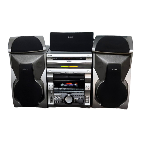
HCD-V919AV is the Amplifier, Video CD
player, Tape Deck and Tuner section in
MHC-V919AV.
This stereo system is equipped with the Dolby B-
type noise reduction system and Dolby Pro Logic
Surround decoder*.
* Manufactured under license from Dolby Labora-
tories Licensing Corporation.
DOLBY, the double-D symbol a and "PRO LOGIC"
are trademarks of Dolby Laboratories Licensing Cor-
poration.
MICROFILM
HCD-V919AV
Model Name Using Similar Mechanism
CD Mechanism Type
CD
Section
Base Unit Name
Optical Pick-up Name
Model Name Using Similar Mechanism
Tape
Deck
Tape Transport Mechanism Type
Section
SPECIFICATIONS
MINI Hi-Fi COMPONENT SYSTEM
E Model
Chinese Model
HCD-V717
CDM38L-5BD24AL
BU-5BD24AL
KSS-213D/Q-NP
HCD-V717
TCM-230AWR1/
230PWR1
– Continued on next page –
Advertisement
Table of Contents

Related Manuals for Sony HCD-V919AV


Summary of Contents for Sony HCD-V919AV
- Page 1 HCD-V919AV SERVICE MANUAL E Model Chinese Model HCD-V919AV is the Amplifier, Video CD player, Tape Deck and Tuner section in MHC-V919AV. This stereo system is equipped with the Dolby B- Model Name Using Similar Mechanism HCD-V717 type noise reduction system and Dolby Pro Logic...
-
Page 2: Table Of Contents
TABLE OF CONTENTS SERVICING NOTES ..........GENERAL ..............DISASSEMBLY ............10 TEST MODE ............. 13 MECHANICAL ADJUSTMENTS ...... 16 ELECTRICAL ADJUSTMENTS DECK Section ..............16 CD Section ..............19 VIDEO Section .............. 21 DIAGRAMS 7-1. Block Diagram – SERVO Section – ......23 7-2. -
Page 3: Servicing Notes
LINE WITH MARK ! ON THE SCHEMATIC DIAGRAMS AND IN THE PARTS LIST ARE CRITICAL TO SAFE OPERATION. REPLACE THESE COMPONENTS WITH SONY PARTS WHOSE PART NUMBERS APPEAR AS SHOWN IN THIS MANUAL OR IN SUPPLEMENTS PUB- LISHED BY SONY. - Page 4 MODEL IDENTIFICATION IC502 OF VIDEO BOARD – Back Panel – IC502 of the VIDEO board consists of the former type and new PART No. type. The following table shows the differences between the two types. Only spare parts for the new type IC502 are supplied. Units using the former IC502 will not function when replaced with the new type without performing the following procedure.
- Page 5 HOW TO OPEN THE DISC TRAY WHEN POWER SWITCH TURNS OFF 1 Remove the case. 3 pull-out the disc tray. 2 Turn the cam to the direction of arrow. NOTE FOR INSTALLATION (ROTARY ENCODER) Note: When attaching the Base unit, Insert the BU cam section A into the groove of BU cam.
-
Page 6: General
SECTION 2 GENERAL LOCATION OF CONTROLS • Front view 1/u (POWER) button DISC 1 button and indicator DISC 2 button and indicator DISC 3 button and indicator DISC SKIP/EX-CHANGE button § button Disc tray Decoration #¢ § button (Deck B) Deck A 9, ( buttons and indicators !¡... - Page 7 #§ Display window #¶ PBC OFF indicator #• PBC indicator #§ #ª VIDEO CD indicator $º PLAY MODE, DOLBY NR, TUNER MEMORY button #¶ ^§ $¡ EDIT, DIRECTION button #• ^∞ $™ REPEAT, STEREO/MONO button #ª ^¢ $£ r REC button and indicator $º...
- Page 8 • Rear view 1 2 3 S VIDEO OUT jack SYSTEM SELECT switch VIDEO OUT jack FM antenna terminal AM antenna terminals VOLTAGE SELECTOR switch SURROUND SPEAKER, CENTER terminals SURROUND SPEAKER, REAR terminals FRONT SPEAKER terminals SUPER WOOFER jack !¢ !£...
- Page 9 This section is extracted from instruction manual. – 9 –...
-
Page 10: Disassembly
SECTION 3 DISASSEMBLY Note: Follow the disassembly procedure in the numerical order given. LOADING PANEL 4 loading panel 3 two claws 1 Turn the cam to the direction of arrow. 2 Pull-out the disc tray. FRONT PANEL 4 flat type wire (CN107) 4 flat type wire (CN106) - Page 11 6 three screws CASSETTE MECHANISM DECK (BVTP2.6 × 8) 7 mechanism deck 6 two screws (BVTP2.6 × 8) 1 two screws 4 Remove the cassette lids. (BVTT2 × 4) 8 two screws (BVTP2.6 × 8) 2 damper, oil 2 damper, oil 1 two screws (BVTT2 ×...
- Page 12 DISC TRAY Note: When installing the Disc tray, pull around the flat type wire to (Perform after removing the front panel.) pass through the claw A and claw B , as shown in the figure. 3 flat type wire (8 core) 4 two claws 2 Pull-out the disc tray.
-
Page 13: Test Mode
SECTION 4 TEST MODE [MC Cold Reset] [Change-over of MW Tuner Step between 9 kHz and • The cold reset clears all data including preset data stored in the 10 kHz] RAM to initial conditions. Execute this mode when returning •... - Page 14 [Aging Mode] Operations during aging This mode can be used for checking the operations of the CD player • Operations are performed in the following sequence during ag- and tape deck. ing. • When problems occur: Aging stops. If currently aging the tape deck, the state when <CD player>...
- Page 15 [VIDEO CD Color-bars Mode] On this mode, the data of the color-bars signal as a picture signal and the 1 kHz sine wave signal as a sound signal are output by the mechanism controller (IC502) for the video CD signal check. When measurement of the voltage and waveform on the VIDEO board, perform it in this mode.
-
Page 16: Mechanical Adjustments
SECTION 5 SECTION 6 MECHANICAL ADJUSTMENTS ELECTRICAL ADJUSTMENTS Precaution DECK SECTION 0 dB=0.775 V 1. Clean the following parts with a denatured alcohol-moistened swab: 1. Demagnetize the record/playback head with a head demagne- record/playback heads pinch rollers tizer. erase head rubber belts 2. - Page 17 3. Mode: Playback (FWD) DECK B Tape Speed Adjustment Note: Start the Tape Speed adjustment as below after setting to the test test tape mode. P-4-A100 MAIN board oscilloscope (10 kHz, –10 dB) In the test mode, the tape speed is high during pressing the CN301 [HI-DUB] button.
- Page 18 DECK B REC Bias Adjustment 4. Mode: Record Procedure: MD/VIDEO (AUDIO) IN INTRODUCTION 315 Hz, 50 mV (–23.8 dB) AF OSC When set to the test mode performed in Tape Speed Adjustment, blank tape when the tape is rewound after recording, the “REC memory mode” 600 Ω...
-
Page 19: Cd Section
RF signal waveform CD SECTION VOLT/DIV: 200 mV Notes: TIME/DIV: 500 ns 1. CD block basically constructed to operate without adjustment. There- (with the 10: 1 probe fore, check each item in order given. in use) 2. Use YEDS-18 disc (Part No.: 3-702-101-01) unless otherwise indicated. 3. - Page 20 Connection Location: [BD Board] (Side A) CN102 IC101 IC103 (FOK) (TE) TP (RF) TP (VC) (FE) – 20 –...
-
Page 21: Video Section
VIDEO SECTION Frequency Adjustment Connection: frequency counter VIDEO board TP508 (27 MHz) – Procedure: 1. Connect the frequency counter to TP508 (27 MHz) on VIDEO board. 2. Turned power switch on. [FUNCTION] 3. Press the button to select the CD. 4. -
Page 22: Diagrams
HCD-V919AV SECTION 7 DIAGRAMS 7-1. BLOCK DIAGRAM – SERVO Section – MCLK IC104 33.8MHz (Page 25) FILTER RF AMP, FOCUS/TRACKING ERROR AMP IC103 DETECTOR A+5V XTSL CTL1 CLOCK DIGITAL SIGNAL PROCESSOR GENERATOR IC101 (1/2) DATA, BCK, LRCK, C2PO DATA DATA... -
Page 23: Block Diagram - Audio/Video Cd Section
HCD-V919AV 7-2. BLOCK DIAGRAM – AUDIO/VIDEO CD Section – (Page 24) DIGITAL FILTER, D/A CONVERTER IC509 (Page 29) MPEG VIDEO/AUDIO DECODER, DIGITAL DA-DATA DATA VOUTL CD-L VIDEO SIGNAL PROCESSOR MPEG INPUT LOW-PASS AUDIO FILTER, DA-BCK LOW-PASS IC505 AUDIO INTERFACE FILER... -
Page 24: Block Diagram - Tape Deck Section
HCD-V919AV 7-3. BLOCK DIAGRAM – TAPE DECK Section – DECK PROCESS DECK A/B SELECT, PB/REC EQ AMP, DOLBY NR AMP, ALC, AMS • SIGNAL PATH IC301 : PLAYBACK (DECK A) HP101 DOLBY PASS (PLAYBACK) : PLAYBACK (DECK B) PB OUT (L) -
Page 25: Block Diagram - Main Section (1/2)
HCD-V919AV 7-4. BLOCK DIAGRAM – MAIN Section (1/2) – (Page 33) • SIGNAL PATH REC-L (Page 28) J750 RV751 : CD PLAY MIC 2 ECHO LEVEL : TAPE PLAY J101 (2/2) : RECORD DIGITAL ECHO MD OUT : TUNER (FM/AM) -
Page 26: Block Diagram – Main Section (2/2)
HCD-V919AV 7-5. BLOCK DIAGRAM – MAIN Section (2/2) – J755 PHONES L-CH POWER AMP (Page 30) IC201 (1/2) – D311 FEED BACK TM401 (Page 30) FRONT SPEAKER IMPEDANCE USE 6 – 16Ω POWER AMP R-CH IC201 (2/2) OVER LOAD DC DETECT –... -
Page 27: Block Diagram - Display/Key Control/Power Supply Section
HCD-V919AV 7-6. BLOCK DIAGRAM – DISPLAY/KEY CONTROL/POWER SUPPLY Section – POWER (Page 29) D610, 612, 620 – 628, D631 – 633, 640 – 644, B+ SWITCH LED +5.6V D651, 652, 655, 656 Q601, 602 CD-POWER (Page 29) D613 – 618,... -
Page 28: Note For Printed Wiring Boards And Schematic Diagrams
• Circuit Boards Location 7-7. NOTE FOR PRINTED WIRING BOARDS AND SCHEMATIC DIAGRAMS TRANSFORMER board Note on Schematic Diagrams: Note on Printed Wiring Boards: • X : parts extracted from the component side. • All capacitors are in µF unless otherwise noted. pF: µµF 50 WV or less are not indicated except for electrolytics •... -
Page 29: Printed Wiring Board – Bd Section
HCD-V919AV 7-8. PRINTED WIRING BOARDS – BD Section – • See page 35 for Circuit Boards Location. • Semiconductor (Page 42) Location Ref. No. Location IC101 IC102 C-10 IC103 IC104 Q101 E-12 Q102 Q103 – 37 – – 38 –... -
Page 30: Schematic Diagram - Bd Section
HCD-V919AV 7-9. SCHEMATIC DIAGRAM – BD Section – • See page 86 for Waveforms. • See page 90 and 91 for IC Block Diagrams. (Page 43) The components identified by mark ! or dotted line with mark ! are critical for safety. -
Page 31: Printed Wiring Board – Video Section
HCD-V919AV 7-10. PRINTED WIRING BOARD – VIDEO Section – • See page 35 for Circuit Boards Location. • Semiconductor • Semiconductor Location Location Ref. No. Location Ref. No. Location D301 IC501 D501 IC502 D502 IC506 IC101 Q302 IC401 Q303 IC402... -
Page 32: Schematic Diagram - Video Section (1/2)
HCD-V919AV 7-11. SCHEMATIC DIAGRAM – VIDEO Section (1/2) – • See page 91 for IC Block Diagram. (Page 39) (Page 62) (Page 45) • Voltages and waveforms are dc with respect to ground in *Note VIDEO CD play mode. When replacing IC502, refer to “IC502 of no mark : VIDEO CD play VIDEO board”... -
Page 33: Schematic Diagram - Video Section (2/2)
HCD-V919AV 7-12. SCHEMATIC DIAGRAM – VIDEO Section (2/2) – • See page 86 to 88 for Waveforms. • See page 91 for IC Block Diagram. (Page 43) – 45 – – 46 –... -
Page 34: Printed Wiring Boards - Cd Motor Section
HCD-V919AV 7-13. PRINTED WIRING BOARDS – CD MOTOR Section – • See page 35 for Circuit Boards Location. (Page 58) MAIN BOARD CN104 (Page 58) MAIN BOARD CN103 – 47 – – 48 –... -
Page 35: Schematic Diagram - Cd Motor Section
HCD-V919AV 7-14. SCHEMATIC DIAGRAM – CD MOTOR Section – • See page 92 for IC Block Diagrams. MAIN BOARD CN104 (Page 62) MAIN BOARD CN103 (Page 62) – 49 – – 50 –... -
Page 36: Printed Wiring Board - Tape Deck Section
HCD-V919AV 7-15. PRINTED WIRING BOARD – TAPE DECK Section – • See page 35 for Circuit Boards Location. (Page 57) MAIN BOARD CN106 – 51 – – 52 –... -
Page 37: Schematic Diagram - Tape Deck Section
HCD-V919AV 7-16. SCHEMATIC DIAGRAM – TAPE DECK Section – • See page 92 for IC Block Diagram. MAIN BOARD CN106 (Page 60) The components identified by mark ! or dotted line with mark ! are critical for safety. Replace only with part number specified. -
Page 38: Printed Wiring Board - Leaf Sw Section
HCD-V919AV 7-17. PRINTED WIRING BOARD – LEAF SW Section – • See page 35 for Circuit Boards Location. MAIN BOARD CN107 (Page 57) 7-18. SCHEMATIC DIAGRAM – LEAF SW Section – MAIN BOARD CN107 (Page 60) – 55 – – 56 –... -
Page 39: Printed Wiring Board – Main Section
HCD-V919AV 7-19. PRINTED WIRING BOARD – MAIN Section – • See page 35 for Circuit Boards Location. (Page 47) (Page 47) (Page 42) • Semiconductor Location Ref. No. Location D502 (Page 56) D508 D901 D931 D932 D951 D952 D953 D954... -
Page 40: Schematic Diagram - Main Section (1/4)
HCD-V919AV 7-20. SCHEMATIC DIAGRAM – MAIN Section (1/4) – (Page 56) (Page 54) (Page 61) (Page 61) (Page 65) (Page 65) (Page 61) (Page 63) (Page 63) (Page 65) • Voltages and waveforms are dc with respect to ground under no-signal (detuned) conditions. -
Page 41: Schematic Diagram - Main Section (2/4)
HCD-V919AV 7-21. SCHEMATIC DIAGRAM – MAIN Section (2/4) – • See page 88 for Waveforms. (Page 60) (Page 43) (Page 60) (Page 50) (Page 50) (Page 60) • Voltages and waveforms are dc with respect to ground under no-signal (detuned) conditions. -
Page 42: Schematic Diagram - Main Section (3/4)
HCD-V919AV 7-22. SCHEMATIC DIAGRAM – MAIN Section (3/4) – • See page 93 for IC Block Diagrams. (Page 59) (Page 59) (Page 65) (Page 65) (Page 65) (Page 62) (Page 85) • Voltages and waveforms are dc with respect to ground under no-signal (detuned) conditions. -
Page 43: Schematic Diagram - Main Section (4/4)
HCD-V919AV 7-23. SCHEMATIC DIAGRAM – MAIN Section (4/4) – (Page 61) (Page 61) (Page 61) (Page 62) (Page 60) (Page 60) (Page 60) (Page 64) (Page 64) (Page 64) (Page 69) (Page 79) (Page 79) • Voltages and waveforms are dc with respect to ground under no-signal (detuned) conditions. -
Page 44: Printed Wiring Board - Panel Section
HCD-V919AV 7-24. PRINTED WIRING BOARD – PANEL Section – • See page 35 for Circuit Boards Location. • Semiconductor Location Ref. No. Location D601 D602 D603 D620 C-10 D621 D622 D623 D624 D625 D626 D627 D628 D629 D630 D651 D652... -
Page 45: Schematic Diagram - Panel Section
HCD-V919AV • Voltages and waveforms are dc with respect to ground under no-signal (detuned) conditions. 7-25. SCHEMATIC DIAGRAM – PANEL Section – • See page 89 for Waveforms. • See page 92 for IC Block Diagrams. no mark : FM ∗... -
Page 46: Printed Wiring Boards - Display Section
HCD-V919AV 7-26. PRINTED WIRING BOARDS – DISPLAY Section – • See page 35 for Circuit Boards Location. (Page 68) (Page 67) (Page 68) – 71 – – 72 –... -
Page 47: Schematic Diagram - Display Section
HCD-V919AV 7-27. SCHEMATIC DIAGRAM – DISPLAY Section – (Page 70) (Page 69) (Page 70) • Voltages and waveforms are dc with respect to ground under no-signal (detuned) conditions. no mark : FM – 73 – – 74 –... -
Page 48: Schematic Diagram - Mic/Headphone Section
HCD-V919AV 7-28. SCHEMATIC DIAGRAM – MIC/HEADPHONE Section – 7-29. PRINTED WIRING BOARDS – MIC/HEADPHONE Section – • See page 92 for IC Block Diagrams. • See page 35 for Circuit Boards Location. (Page 78) (Page 79) (Page 77) (Page 79) •... -
Page 49: Printed Wiring Board - Power Amp Section
HCD-V919AV 7-30. PRINTED WIRING BOARD – POWER AMP Section – • See page 35 for Circuit Boards Location. • Semiconductor Location Ref. No. Location D101 D102 D103 D104 D105 D111 D112 D113 D114 D201 D251 D301 D311 D321 D331 D332... -
Page 50: Schematic Diagram - Power Amp Section
HCD-V919AV 7-31. SCHEMATIC DIAGRAM – POWER AMP Section – (Page 75) (Page 81) (Page 66) (Page 81) (Page 75) (Page 81) (Page 66) (Page 81) (Page 81) • Voltages and waveforms are dc with respect to ground The components identified by mark ! or dotted under no-signal (detuned) conditions. -
Page 51: Schematic Diagram - Transformer Section
HCD-V919AV 7-32. SCHEMATIC DIAGRAM – TRANSFORMER Section – • See page 83 for Printed Wiring Board. (POWER BOARD) • See page 83 for Printed Wiring Board. (TRANSFORMER BOARD) (Page 80) (Page 80) (Page 80) (Page 80) (Page (Page 80) • Voltages and waveforms are dc with respect to ground The components identified by mark ! or dotted under no-signal (detuned) conditions. -
Page 52: Printed Wiring Board - Transformer Section
HCD-V919AV 7-33. PRINTED WIRING BOARD – TRANSFORMER Section – • See page 35 for Circuit Boards Location. 7-34. PRINTED WIRING BOARD – SURROUND Section – • See page 35 for Circuit Boards Location. (Page 58) (Page 78) (Page 78) – 83 –... -
Page 53: Schematic Diagram - Surround Section
HCD-V919AV 7-35. SCHEMATIC DIAGRAM – SURROUND Section – (Page 63) (Page • Voltages and waveforms are dc with respect to ground The components identified by mark ! or dotted under no-signal (detuned) conditions. line with mark ! are critical for safety. - Page 54 • Waveforms – BD Board – 1 IC101 @§ (RFDC) – VIDEO Board – 6 IC101 $¶ (BCLK) 1 IC501 5 (LRCK) 200 mV/DIV, 500 ns/DIV +0.25 Vp-p –0.20 5.2 Vp-p 5 Vp-p 22.8 µ s 474 ns 2 IC101 @¶ (TE) !£...
- Page 55 !ª &∞ !§ IC505 `⁄⁄⁄ (DA-BCK), IC509 !¶ (BCK) 6 IC402 !¡ IC505 (XIN) (C-OUT) 0.5 Vp-p 4.8 Vp-p 3.4 Vp-p 8.1 MHz 472 ns @º 7 IC402 *§ !™ IC505 !¶ Q301 (Base) (XOUT) (DA-XCLK) 1.8 Vp-p 4.2 Vp-p 5.2 Vp-p 8.1 MHz 60 ns...
- Page 56 – MAIN Board – @§ IC401 3 @¡ IC509 @º (384FSO) 1 IC501 0 (X2) 5.1 Vp-p 1 Vp-p 5.5 Vp-p 5 MHz 59 ns @™ IC509 @¡ (768FSO) @¶ IC401 1 2 IC501 !£ (XT2) 4.8 Vp-p 5 Vp-p 2 Vp-p 32.768 kHz 30 ns...
- Page 57 – PANEL Board – 1 IC601 8 (X-OUT) 4 Vp-p 8 MHz 2 IC801 2 (X-OUT) 4.3 Vp-p 8 MHz 3 IC851 2 (XT) 3.6 Vp-p 4.09 MHz – 89 –...
-
Page 58: Ic Block Diagrams
• IC Block Diagrams – BD Board – IC101 CXD2545Q 61 – 51 DA16 EXCK DA12 LRCK WDCK SQSO PSSL SQCK MUTE SENS XRST DIRC ASYE SCLK DFSW ATSK AVDD ASYO DATA XLAT CLOK ASYI MIRR DFCT BIAS RFAC AVSS CLTV FILI LOCK... -
Page 59: Video Board
IC103 CXA1821M-T6 LD ON LC/PD APC LD AMP VREF RF EQ AMP RF SUMMING AMP FOCUS ERROR AMP FE BIAS TRACKING ERROR AMP VC BUFFER –VIDEO Board – IC509 PCM1727E-2/T2 384fs CLOCK MANAGER • DUAL PLL DGND PGND POWER SUPPLY SCKO1 SCKO2 NCKO... -
Page 60: Panel Board
– MOTOR (TURN) Board – – PANEL Board – IC701 M54641L IC603 BA3833F-E2 RESET 18 RESET RESET REFERENCE REFFERENCE PREF 17 f01 POWER OUT2 INPUT CURRENT AMP. AMP. CONTROL LINE 16 f02 POWER OUT1 INPUT AMP. AMP. LINE 15 f03 BIAS 13 f Bias... - Page 61 – MAIN Board – IC201 LV1041M R BPF2 L BPF2 RECT RECT LOGIC LOGIC R BPF1 RECT RECT L BPF1 LOGIC LOGIC RT IN S DC OUT C DC OUT R DC OUT LT IN L DC OUT CONTROL DC CUT V REF V REF CONTROL...
-
Page 62: Ic Pin Function Description
7-36. IC PIN FUNCTION DESCRIPTION • MAIN BOARD IC501 µPD780016AYGF-014-3BA (SYSTEM CONTROLLER) Pin No. Pin Name Function LINE-MUTE Line muting on/off control signal output terminal “L”: muting on DBFB normal/high selection signal output to the M62442FP (IC101) DBFB-H/L “L”: DBFB high, “H”: DBFB low M62442-LATCH Serial data latch pulse output to the M62442FP (IC101) KEYCON-LATCH... - Page 63 Pin No. Pin Name Function COM-CLK Serial data transfer clock signal output terminal Not used (open) Power on/off control signal output for the CD and video CD section CD-POWER “H”: power on, “L”: standby CD-DATA Serial data output terminal Not used (open) CD-CLK Serial data transfer clock signal output terminal Not used (open) PL-CLK...
- Page 64 Pin No. Pin Name Function ENC3 ENC2 Detection signal input from the disc tray address detect rotary encoder (S811) ENC1 Detection signal input from the disc tray open/close detect switch (S801) OUT-OPEN “L”: open, “H”: close High/normal speed selection signal output of the capstan motor (M1) CAP-M-H/L “L”: high speed, “H”: normal speed B-TRG...
- Page 65 • VIDEO BOARD IC502 (CD MECHANISM CONTROLLER) Former type M30620MC-302FP New type M30620MC-305FP Pin No. Pin Name Function SENSE Internal status (SENSE) signal input from the CXD2545Q (IC101) SENSE CLK Sense serial data reading clock signal output to the CXD2545Q (IC101) DSP DATA Serial data output to the CXD2545Q (IC101) DSP LATCH...
- Page 66 Pin No. Pin Name Function Not used (open) BUS XHOLD Hold signal input terminal Not used (fixed at “H”) 42, 43 Not used (open) SHIMUKE Destination setting terminal “L”: Chinese, “H”: English Vertical synchronized signal input from the MPEG video/audio decoder (IC505) “L” active BUS XWRL Not used (open) LO.BOOST...
- Page 67 • VIDEO BOARD IC505 CL680T-D1 (MPEG VIDEO/AUDIO DECODER, VIDEO SIGNAL PROCESSOR) Pin No. Pin Name Function Not used (open) — Ground terminal CD-BCK CD decode bit clock signal (2.8224 MHz) input from the CXD2545Q (IC101) CD-DATA CD decode data input from the CXD2545Q (IC101) CD-LRCK CD decode L/R sampling clock signal (44.1 kHz) input from the CXD2545Q (IC101) CD-C2PO...
- Page 68 Pin No. Pin Name Function RREF Fix the video signal output level control VREF Reference voltage (+1.235V) output terminal AVDD-DAC — Power supply terminal (+3.3V) (for D/A converter) C-OUT Chrominance video signal output terminal AGND-DAC — Ground terminal (for D/A converter) GCK (pin `⁄‚fi) selection terminal “L”: external clock, “H”: internal clock (fixed at “H”) CLK-SEL0 DA-XCLK (pin *§) selection (1) terminal Fixed at “H”...
- Page 69 Pin No. Pin Name Function VDD3 — Power supply terminal (+3.3V) HSEL Command selection signal input from the CD mechanism controller (IC502) CDG-SDATA Not used (fixed at “L”) CDG-VFSY Not used (fixed at “L”) CDG-S0S1 Not used (fixed at “L”) 125 to 128 Not used (open) –...
- Page 70 • PANEL BOARD IC601 TMP87CM74AF-6731 (FLUORESCENT INDICATOR TUBE DRIVE, LED DRIVE, KEY CONTROL) Pin No. Pin Name Function LED3 LED drive signal output terminal (for decoration LED) LED4 LED drive signal output terminal (for decoration LED) LED5 LED drive signal output terminal (DISC 3) LED6 LED drive signal output terminal (DISC 2) LED7...
- Page 71 Pin No. Pin Name Function Spectrum analyzer drive signal input from the spectrum analyzer band-pass filter (IC603) SPEANA-1 (for low frequency) Spectrum analyzer drive signal input from the spectrum analyzer band-pass filter (IC603) SPEANA-2 (for low and middle frequency) Spectrum analyzer drive signal input from the spectrum analyzer band-pass filter (IC603) SPEANA-3 (for middle and high frequency) Spectrum analyzer drive signal input from the spectrum analyzer band-pass filter (IC603)
- Page 72 • PANEL BOARD IC801 TMP87CH48DF-4825 (CSV CONTROL, LED DRIVE, KEY CONTROL) Pin No. Pin Name Function — Ground terminal X-OUT System clock output terminal (8 MHz) X-IN System clock input terminal (8 MHz) System reset signal input from the reset signal generator (IC951) “L”: reset RESET For several hundreds msec.
- Page 73 Pin No. Pin Name Function 41 to 56 Not used (open) 57 to 60 — Ground terminal BPM LED-B LED drive signal output terminal (AUTO BPM) “L”: LED on BPM-LED-A LED drive signal output terminal (AUTO BPM) “L”: LED on BOMBER-LED LED drive signal output terminal (BEAT JAM) “L”: LED on ON/OFF-LED...
-
Page 74: Exploded Views
SECTION 8 EXPLODED VIEWS NOTE: • -XX and -X mean standardized parts, so they • Items marked “*” are not stocked since they The components identified by mark ! or dotted line with mark may have some difference from the original are seldom required for routine service. - Page 75 (2) CHASSIS SECTION not supplied not supplied (SP,MY) (IA) (SP,MY) (IA,TH,CH) T501 not supplied The components identified by mark ! or dotted line with mark ! are critical for safety. Replace only with part number specified. Ref. No. Part No. Description Remark Ref.
- Page 76 4-951-620-01 SCREW (2.6X8), +BVTP 4-996-811-01 KNOB (VOL) * 124 1-668-271-11 HEADPHONE BOARD X-4949-983-1 PANEL ASSY, FRONT 4-986-893-51 KNOB (MICROPHONE) 4-962-708-21 EMBLEM (4-A), SONY * 126 A-4414-041-A MIC BOARD, COMPLETE 4-988-663-01 FOOT (FELT) X-4949-941-1 LID (L) ASSY, CASSETTE * 113 A-4414-044-A CONT-PANEL BOARD, COMPLETE...
- Page 77 (4) CD MECHANISM DECK SECTION-1 (CDM38L-5BD24AL) M701 Ref. No. Part No. Description Remark Ref. No. Part No. Description Remark 4-981-789-11 BRACKET (2), YOKE 4-977-941-01 BEARING (WORM) 4-977-945-01 TRAY (TURN) * 209 1-658-576-11 SENSOR BOARD X-4946-665-1 SHAFT ASSY, WORM 4-934-376-01 SHAFT (ROLLER) 4-977-943-01 BELT (TURN) (1.2) 4-981-187-01 COLLAR (WORM) 4-977-956-01 WHEEL, WORM...
- Page 78 (5) CD MECHANISM DECK SECTION-2 (CDM38L-5BD24AL) supplied M801 BU-5BD24AL S811 Ref. No. Part No. Description Remark Ref. No. Part No. Description Remark 4-981-789-11 BRACKET (2), YOKE * 262 1-658-578-11 MOTOR (SLIDE) BOARD 4-977-954-01 PULLEY (SL) 4-982-447-01 SPRING (BU), COMPRESSION 4-977-953-01 GEAR (SL-A) 4-951-620-41 SCREW (2.6), +BVTP 4-977-955-01 GEAR (SL-B) * 265...
- Page 79 (6) BASE UNIT SECTION (BU-5BD24AL) M101 M102 The components identified by mark ! or dotted line with mark ! are critical for safety. Replace only with part number specified. Ref. No. Part No. Description Remark Ref. No. Part No. Description Remark ! 301 8-820-020-02 OPTICAL PICK-UP KSS-213D/Q-NP...
- Page 80 (7) TAPE MECHANISM DECK SECTION-1 TCM-230AWR1 TCM-230PWR1 * NOTE: Two types of parts which are not interchangeable are available for the Head deck (A) ASSY and Head deck (B) ASSY. When replacing the parts, refer to the following figure, and use the appropriate part Parts with “P”...
- Page 81 (8) TAPE MECHANISM DECK SECTION-2 TCM-230AWR1 TCM-230PWR1 * NOTE: Two types of parts which are not interchangeable are available for the mechanical block assembly. When replacing the parts, refer to the following figure, and use the appropriate part. Parts with “P” mark: 230PWR1 Parts without “P”...
-
Page 82: Electrical Parts List
SECTION 9 AUDIO ELECTRICAL PARTS LIST NOTE: • Due to standardization, replacements in the • Items marked “*” are not stocked since they The components identified by mark ! or dotted line with mark parts list may be different from the parts speci- are seldom required for routine service. - Page 83 AUDIO Ref. No. Part No. Description Remark Ref. No. Part No. Description Remark R612 1-249-409-11 CARBON 1/4W < CONNECTOR > ! R621 1-212-851-00 FUSIBLE 1/4W F ! R622 1-212-851-00 FUSIBLE 1/4W F CN101 1-770-706-11 CONNECTOR, FFC/FPC 23P R623 1-249-432-11 CARBON 1/4W CN102 1-770-425-11 CONNECTOR, FFC/FPC 16P...
- Page 84 CD SWITCH CONNECTOR CONT-PANEL Ref. No. Part No. Description Remark Ref. No. Part No. Description Remark R175 1-216-025-00 RES,CHIP 1/10W < TRANSISTOR > R176 1-216-073-00 METAL CHIP 1/10W R177 1-216-073-00 METAL CHIP 1/10W Q701 8-729-900-80 TRANSISTOR DTC114ES R178 1-216-073-00 METAL CHIP 1/10W <...
- Page 85 CONT-PANEL DECORATION HEADPHONE LEAF SW Ref. No. Part No. Description Remark Ref. No. Part No. Description Remark R670 1-216-037-00 METAL CHIP 1/10W Q857 8-729-027-60 TRANSISTOR DTC144TKA-T146 R671 1-216-031-00 METAL CHIP 1/10W R811 1-216-029-00 METAL CHIP 1/10W < RESISTOR > R812 1-216-029-00 METAL CHIP 1/10W R706...
- Page 86 LEAF SW MAIN Ref. No. Part No. Description Remark Ref. No. Part No. Description Remark R1004 1-247-834-11 CARBON 1.3K 1/4W C161 1-137-195-11 FILM 0.56uF R1005 1-247-818-11 CARBON 1/4W C162 1-163-986-00 CERAMIC CHIP 0.027uF R1006 1-247-864-11 CARBON 1/4W C163 1-136-167-00 FILM 0.15uF R1007 1-247-856-00 CARBON...
- Page 87 MAIN Ref. No. Part No. Description Remark Ref. No. Part No. Description Remark C234 1-104-664-11 ELECT 47uF C358 1-126-964-11 ELECT 10uF C235 1-126-961-11 ELECT 2.2uF C359 1-136-173-00 FILM 0.47uF C236 1-126-961-11 ELECT 2.2uF C371 1-163-009-11 CERAMIC CHIP 0.001uF C372 1-163-009-11 CERAMIC CHIP 0.001uF C237 1-136-165-00 FILM...
- Page 88 MAIN Ref. No. Part No. Description Remark Ref. No. Part No. Description Remark < CONNECTOR > < JACK > * CN101 1-568-832-11 SOCKET, CONNECTOR 13P J101 1-774-411-11 JACK, PIN 6P (VIDE0 (AUDIO) IN, MD IN/OUT) CN102 1-784-600-11 SOCKET, CONNECTOR (NON ZIF)15P J191 1-774-785-11 JACK, PIN 1P (SUPER WOOFER) (EXCEPT TH)
- Page 89 MAIN Ref. No. Part No. Description Remark Ref. No. Part No. Description Remark Q932 8-729-900-36 TRANSISTOR DTC124ES R171 1-216-073-00 METAL CHIP 1/10W Q933 8-729-040-20 TRANSISTOR RT1P137L-TP R172 1-216-295-00 SHORT Q934 8-729-900-63 TRANSISTOR DTA124ES R173 1-216-057-00 METAL CHIP 2.2K 1/10W Q935 8-729-141-83 TRANSISTOR 2SB1094-LK Q936 8-729-900-36 TRANSISTOR DTC124ES...
- Page 90 MAIN Ref. No. Part No. Description Remark Ref. No. Part No. Description Remark R328 1-216-094-00 RES, CHIP 1/10W R565 1-216-025-00 RES, CHIP 1/10W R329 1-216-049-11 RES, CHIP 1/10W R566 1-216-025-00 RES, CHIP 1/10W R330 1-216-065-00 RES, CHIP 4.7K 1/10W R331 1-216-065-00 RES, CHIP 4.7K 1/10W...
- Page 91 MOTOR (SLIDE) MOTOR (TURN) Ref. No. Part No. Description Remark Ref. No. Part No. Description Remark A-4414-041-A MIC BOARD, COMPLETE R752 1-216-097-00 RES, CHIP 100K 1/10W R753 1-216-049-11 RES, CHIP 1/10W ******************* R754 1-216-089-00 RES, CHIP 1/10W < CAPACITOR > R755 1-216-073-00 METAL CHIP 1/10W...
- Page 92 MOTOR (TURN) PANEL Ref. No. Part No. Description Remark Ref. No. Part No. Description Remark < CONNECTOR > C807 1-163-017-00 CERAMIC CHIP 0.0047uF 5% C808 1-163-017-00 CERAMIC CHIP 0.0047uF 5% CN703 1-750-413-11 CONNECTOR, FFC/FPC 8P C809 1-104-664-11 ELECT 47uF CN704 1-506-469-11 PIN, CONNECTOR 4P C851 1-163-038-00 CERAMIC CHIP...
- Page 93 PANEL Ref. No. Part No. Description Remark Ref. No. Part No. Description Remark JR912 1-216-295-00 SHORT R619 1-216-089-00 RES, CHIP 1/10W JR913 1-216-296-00 SHORT R621 1-216-075-00 METAL CHIP 1/10W JR914 1-216-296-00 SHORT R622 1-216-039-00 METAL CHIP 1/10W JR915 1-216-296-00 SHORT R623 1-216-041-00 METAL CHIP 1/10W...
- Page 94 PANEL POWER AMP Ref. No. Part No. Description Remark Ref. No. Part No. Description Remark R802 1-216-025-00 RES, CHIP 1/10W C104 1-164-159-21 CERAMIC 0.1uF R803 1-216-025-00 RES, CHIP 1/10W C105 1-126-943-11 ELECT 2200uF R804 1-216-025-00 RES, CHIP 1/10W C106 1-162-294-31 CERAMIC 0.001uF R805 1-216-075-00 METAL CHIP...
- Page 95 POWER AMP Ref. No. Part No. Description Remark Ref. No. Part No. Description Remark C414 1-161-494-00 CERAMIC 0.022uF Q321 8-729-119-78 TRANSISTOR 2SC403SP-51 C415 1-161-494-00 CERAMIC 0.022uF Q322 8-729-900-36 TRANSISTOR DTC124ES Q401 8-729-040-20 TRANSISTOR RT1P137L-TP < CONNECTOR > Q402 8-729-900-80 TRANSISTOR DTC114ES CN201 1-778-981-11 CONNECTOR, BOARD TO BOARD 13P Q404...
- Page 96 POWER AMP SENSOR SURROUND Ref. No. Part No. Description Remark Ref. No. Part No. Description Remark R308 1-247-903-00 CARBON 1/4W R310 1-247-903-00 CARBON 1/4W < TERMINAL > R311 1-249-441-11 CARBON 100K 1/4W TM401 1-537-842-11 TERMINAL BOARD (FRONT SPEAKER) R312 1-249-419-11 CARBON 1.5K 1/4W TM402...
- Page 97 SURROUND TRANSFORMER VIDEO Ref. No. Part No. Description Remark Ref. No. Part No. Description Remark < EARTH TERMINAL > FH508 1-533-233-21 HOLDER, FUSE FH509 1-533-233-21 HOLDER, FUSE * EP601 1-537-738-21 TERMINAL, EARTH (CH) * EP602 1-537-738-21 TERMINAL, EARTH FH510 1-533-233-21 HOLDER, FUSE <...
- Page 98 VIDEO Ref. No. Part No. Description Remark Ref. No. Part No. Description Remark C412 1-165-319-11 CERAMIC CHIP 0.1uF < DIODE > C413 1-124-778-00 ELECT CHIP 22uF 6.3V C452 1-165-319-11 CERAMIC CHIP 0.1uF D301 8-719-054-23 DIODE RB706D-40-T146 C501 1-163-251-11 CERAMIC CHIP 100PF D501 8-719-422-12 DIODE MA8039...
- Page 99 VIDEO Ref. No. Part No. Description Remark Ref. No. Part No. Description Remark Q302 8-729-024-91 TRANSISTOR 2SC2712-GL-TE85L Q303 8-729-024-91 TRANSISTOR 2SC2712-GL-TE85L R411 1-216-073-00 METAL CHIP 1/10W Q304 8-729-024-91 TRANSISTOR 2SC2712-GL-TE85L R412 1-216-073-00 METAL CHIP 1/10W Q306 8-729-027-60 TRANSISTOR DTC144TKA-T146 R413 1-216-025-00 RES,CHIP 1/10W (FORMER TYPE) (*NOTE)
- Page 100 HCD-V919AV VIDEO Ref. No. Part No. Description Remark Ref. No. Part No. Description Remark ! 59 1-558-943-41 CORD, POWER (IA, TH) R550 1-216-025-00 RES,CHIP 1/10W ! 59 1-575-651-21 CORD, POWER (SP, MY) R551 1-216-025-00 RES,CHIP 1/10W ! 59 1-782-510-11 CORD, POWER (CH)
Need help?
Do you have a question about the HCD-V919AV and is the answer not in the manual?
Questions and answers