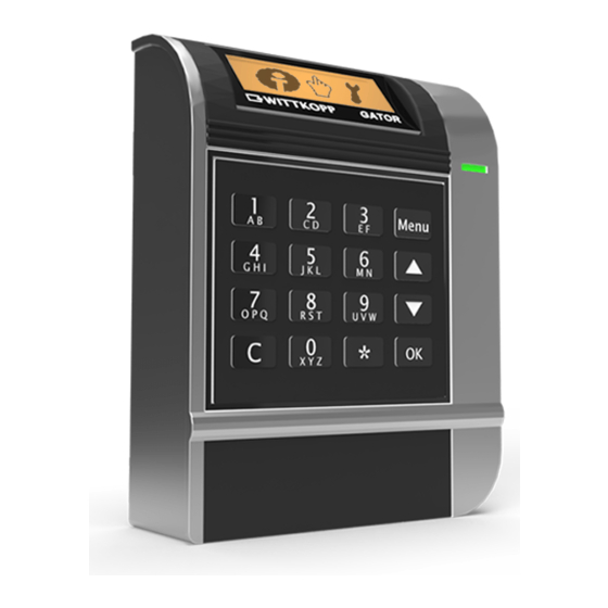
• By opening the lock cover warranty of the manufacturer will be void. • Take care that the input unit or the lock and the cables should not be damaged. 2 System overview GATOR F GATOR DF GATOR R GATOR DR...
Installation instructions Gator 3 Installation input unit Gator RO 3.1 Input unit Gator RO 3.1.1 Dimensions Gator RO 3.2 Installation overview 3.2.1 Input unit Gator RO Fixing ring for input unit Connection axis for turnable input unit Cylinder screws M4 x 10 Connection cable Input unit Türlochbohrung...
Page 4
Installation instructions Gator 3.4 Axis length calculation input unit Gator RO (turnable) 3.4.1 In connection with Gator 2000 3.4.2 In connection with boltwork Achse Achse in gegen gegen ve Secure the axis against shifting in axial direction. Connection axis: Connection axis: Debur the ends Debur the ends L = A + 43 mm (tolerance -4 mm)
Page 5
Installation instructions Gator 3.5.3 Input unit Gator RO (fixed) Drill-hole Ø 3,4 mm in the safe door to fix the input unit • Fit input unit of approx. 20° (see 3.4.2), adjusting to the locked lock/boltwork and insert grub screw M3 x 6 or arrest pin. 3.5.4 Cable guidance Gator RO (turnable) 3.5.5 Plug position Gator RO Audit...
Installation instructions Gator 4 Installation input unit Gator FL 4.1 Input unit Gator FL 4.1.2 Input unit Gator FL 4.1.3 Dimensions Gator FL (fixing on the inside) (fixing on the front) Emergency power supply 4.2 Mounting Ø 92 4.2.1 Drill pattern Gator FL Opening for cable: Drill-hole min.
Installation instructions Gator 5 Installation input unit Gator FS 5.1 Input unit Gator FS 5.1.1 Dimensions Gator FS Ø 95 5.2 Mounting 5.2.1 Drill pattern Gator FS Fixing position for screws M5 Opening for cable: Drill-hole min. Ø 8 mm/max. Ø 11,4 mm for connection cable has to be drilled into the safe door •...
Installation instructions Gator 6 Installation input unit Gator F/DF/R/DR 6.1 Input unit Gator F/DF 6.1.1 Input unit Gator R/DR iButton-reader iButton-reader (optional) (optional) 6.1.2 Dimensions Gator F/DF 6.1.3 Dimensions Gator R/DR Kabeldurchlass/ 6.2 Axis length calculation input unit Gator R/DR 6.2.1 In Verbindung mit Gator 2000...
Page 9
Installation instructions Gator 6.3 Mounting 6.3.1 Drill pattern Gator F/DF/R/DR Fixing position for screws M4 Gator F/DF: Opening for cable: Drill-hole min. Ø 8 mm/max. Ø 11,4 mm for connection cable Gator R/DR: Hole center congruent with middle axis of nut of the electronic lock.
Page 10
• Fig. 2: Fix the safety screw M4 x 16 from the side – optional. • Fig. 3: Gator F/DF: Insert cover cap at the bottom of the input unit. • Fig. 4: Gator R/DR: Insert turning knob and cover cap at the bottom of the input unit.
Page 11
Installation instructions Gator 6.4 Power supply display DIP switch 6.4.1 Power supply via batteries 6.4.2 Power supply via adapter Factory mode • Slide DIP switch at the back of the battery compartment • Slide DIP switch at the back of the battery compartment into illustrated position.
Before mounting the lock the input unit has to be installed (see chapter 3 to 6). Wittkopp electronic locks of the Gator series have got standard fixing points and can be mounted in all 4 directions (right-hand, left-hand, up, down) •...
Page 13
Installation instructions Gator 7.3.2 Dimensions lock Gator 3010 - long connection with mechanical emergency lock Gator 3010 66,5 13,5 Hub/stroke 12 Installation example Area around the 58,3 unlocking lever must be protected especially. 66,5 Mechanical emergency lock 7.4 Dimensions lock Gator 5000/6000/8000/9000 7.4.1 Bolt stroke Attention: Bolt stroke only has to be adjust when lock bolt is completely moved into lo-...
Page 14
Installation instructions Gator 66,5 17,3 7.5.2 Bolt load Gator 2000/3000/3010/5000/6000/8000/9000 • The maximum and constantly bolt load against Ausschlussrichtung?????? may not exceed the following limits: Gator 2000 2,5N Gator 3000 2,5N Gator 5000, 6000, 8000, 9000 30 N 7.6 Plug positions 7.6.1 Gator 2000 7.6.2 Gator 3000/3010 nput unit/...
• Pairing of the address of the redundancy locks is mandatory according to table. • The monitoring of the redundancy is only available with redundant laid bus cables and the input units Gator F/DF/R/DR . • The monitoring of the redundancy is not active - activate configuration in Software GatorSelect and transmit via ibutton.
Installation instructions Gator 9 External power supply • The Gator-System can externaly power supplied by Gator PowerAdapt or GatorSignal plus. • Refer to the corresponding note 6.4 Power supply display for the input units Gator DF/DR. • By energization via adapter it is recommended to remove the batteries. •...
Page 17
• When there are more than 3 locks per system, we recommend to use further more external power supplies. This would need to be verified individually. • Redundancy systems are only available with the input units Gator F/DF/R/DR. Rel. 1.2...
Page 18
This would need to be verified individually. • Redundancy systems are only available with the input units Gator F/DF/R/DR. • Plug in a connection cable for the redundancy between the left and the right electronic (Plug position B - B).
Installation instructions Gator 11 Functional test (when the door is open) Attention: for Gator 5000/6000/8000/9000 danger of collisions! - see below • Connect the power supply: connect the battery 9V block with the battery clip in the input unit or switch on the external power supply.
Need help?
Do you have a question about the GATOR F and is the answer not in the manual?
Questions and answers