Table of Contents
Advertisement
SW
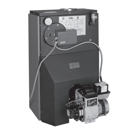
OIL FIRED DIRECT EXHAUST
CAST IRON BOILER
INSTALLATION, OPERATION &
MAINTENANCE MANUAL
Utica Boilers
2210 Dwyer Avenue, Utica NY 13504-4729
Phone: (315) 797-1310 • Fax: (866) 432-7329
e-mail: info@ecrinternational.com
An ISO 9001-2008 Certified Company
P/N# 27515401, Rev. A [03/2011]
web site: www.ecrinternational.com
Advertisement
Table of Contents

Subscribe to Our Youtube Channel
Related Manuals for UTICA BOILERS SW3


Summary of Contents for UTICA BOILERS SW3
- Page 1 OIL FIRED DIRECT EXHAUST CAST IRON BOILER INSTALLATION, OPERATION & MAINTENANCE MANUAL Utica Boilers 2210 Dwyer Avenue, Utica NY 13504-4729 Phone: (315) 797-1310 • Fax: (866) 432-7329 e-mail: info@ecrinternational.com An ISO 9001-2008 Certified Company P/N# 27515401, Rev. A [03/2011] web site: www.ecrinternational.com...
-
Page 2: Table Of Contents
tABLE OF CONtENtS Safety Symbols ........................... 3 Installation ..........................4 Connecting Supply And Return Piping ..................... 5 Recommended Piping For Boilers Equipped With A P3 Or T4 Tankless Heater ........9 Options Utilizing 3/4" Tapping ......................10 Oil Tank And Piping ........................11 Electrical Wiring .........................12 Thermostat Installation .......................13 Normal Sequence Of Operation .....................14... -
Page 3: Safety Symbols
Utica Boilers Installation, Operation and Maintenance manual. DANGER Installing or venting a boiler or any other gas... -
Page 4: Installation
INStALLAtION Minimum clearances to combustible construction are: WARNING TOP ..........0.0 IN. Improper installation, adjustment, alteration, service or maintenance could result in FRONT ........24.0 IN.* FLUE CONNECTOR ......2.0 IN. personal injury or loss of life. REAR ..........0.0 IN. LEFT SIDE ........ -
Page 5: Connecting Supply And Return Piping
CONNECtINg SuppLy ANd REtuRN pIpINg NOTICE Circulators in following illustrations are mounted on system supply side, mounting on system return side is also acceptable practice. Figure 1 - Typical Installation Using Circulators Figure 2 - Typical Installation Using Zone Valves... - Page 6 CONNECtINg SuppLy ANd REtuRN pIpINg Typical installation using circulators shown in Figure • Method used to protect systems using radiant panels and material they are encased in from high temperature supply water from boiler. See Figure Typical installation using zone valves shown in Figure •...
- Page 7 CONNECtINg SuppLy ANd REtuRN pIpINg Figure 4 Figure 5...
- Page 8 CONNECtINg SuppLy ANd REtuRN pIpINg Connect supply and return piping as suggested in Maintain minimum clearance of one inch to hot Figure 6, when boiler is used in connection with water pipes. refrigerated systems: In air handling units where they may be exposed to Chilled medium must be in parallel with the boiler.
-
Page 9: Recommended Piping For Boilers Equipped With A P3 Or T4 Tankless Heater
RECOmmENdEd pIpINg FOR BOILERS EquIppEd WIth A p3 OR t4 tANkLESS hEAtER DANGER Burn, scald hazard. Water temperatures exceeding 125º F will cause severe burns instantly or death by scalding. • An automatic mixing valve must be installed on the outlet of the domestic coil. -
Page 10: Options Utilizing 3/4" Tapping
OptIONS utILIzINg 3/4" tAppINg Figure 8 - Optional Location For Air Vent Figure 9 - Optional Location For Expansion Tank (Non-Diaphragm Type) -
Page 11: Oil Tank And Piping
OIL tANk ANd pIpINg Install Oil tank and piping in accordance with the • Do not run overhead fuel lines from tank to oil burner. National Board of Fire Underwriters and in absence of such • Fuel pump connections and by-pass should be made regulations in accordance with authority having jurisdiction. -
Page 12: Electrical Wiring
ELECtRICAL WIRINg Electrical wiring must conform with National Electrical Component Coding Code ANSI/NFPA No. 70 in United States and CSA C22.1 TH-1 Thermostat (millivolt) Canadian Electrical Code in Canada and/or the local TH-2 Thermostat (24 Volt) authority having jurisdiction. TH-3 Thermostat (Line Voltage) •... -
Page 13: Thermostat Installation
ELECtRICAL WIRINg Figure 13 - Wiring Diagram For Oil Fired Boilers With A Circulator Zoned System And A Tankless Heater thERmOStAt INStALLAtION Check thermostat operation by raising and lowering Install thermostat on inside wall about four feet above floor. thermostat as required to start and stop burner. Instructions for final adjustment of thermostat Never install thermostat on outside wall. -
Page 14: Normal Sequence Of Operation
NORmAL SEquENCE OF OpERAtION • Thermostat will activate, completing circuit to aquastat. • When thermostat is satisfied power is interrupted to boiler mounted aquastat and burner will run in post • Circulator motor starts and power is switched to purge mode for 2 minutes. limit. -
Page 15: Instructions To Obtain Proper Operation Of The Boiler-Burner Unit
INStRuCtIONS tO OBtAIN pROpER OpERAtION OF thE BOILER-BuRNER uNIt Table below is provided as guideline for initial start-up. Final adjustments MUST be made using combustion instruments as previously mentioned. REILLO SETTINGS Boiler Burner Turb. Pump Nozzle Head Damp Setting Pressure Furnished 4.00 150 PSI... -
Page 16: Preventive Maintenance
pREvENtIvE mAINtENANCE Preventive Maintenance of oil fired boiler reduces op- Periodic Inspection and tightening of tankless heater/ erating costs. Boiler and vent pipe should be inspected for cover plate bolts will reduce risk of leaks. See Figure 17. accumulation of soot or scale deposits periodically but at least once every year before start of each heating season. -
Page 17: Service Check List
SERvICE ChECk LISt Inspect Chimney and Flue pipe Pump Pressure/Vacuum Inspect and Clean Appliance Line Voltage/Motor Amps Smoke Test Inspect Oil Line - Size/Leaks Inspect Electrical Connections Draft Over-fire/In Flue or O Install New Filter Flue Gas Temperature Room Make-up Air Electrode setting Proper Light-Off (Hot &... -
Page 18: Sw Series Replacement Parts
SW SERIES REpLACEmENt pARtS Figure 16 - Heat Exchanger ITEM # PART # DESCRIPTION 10051701 REAR SECTION 3 Section 100-1-8.01 #60 PUSH NIPPLE 4 Section FULLY ASSEMBLED HEAT EXCHANGERS 5 Section PART # DESCRIPTION 3 Section 4 Section 3 SECT. WITH 10051101 CENTER SECTION 10023701... - Page 19 SW SERIES REpLACEmENt pARtS Figure 17 - COIL ITEM # PART # DESCRIPTION GA-001.00 GAUGE THERALTIMETER, WATER 2551401 GASKET - SILICON/DURO 70 37519501 HARNESS CIRCULATOR HW08001 BOLT 5/16" X 3/4" 1010001 CONTROL L8148A (FOR BOILERS WITHOUT A TANKLESS COIL) AQ-010.00 CONTROL L8124A (FOR BOILERS WITH A TANKLESS COIL) AQ-020.01 WELL...
- Page 20 SW SERIES REpLACEmENt pARtS Figure 18 - Swing Door And Mounting Door Components ITEM # PART # DESCRIPTION 2552901 MOUNTING DOOR INSULATION & PLUG HW-005.01 SCREW 1/4-20X1/2 SELF TAPPING 10011701 OBSERVATION DOOR 25511101 OBSERVATION DOOR GASKET HW06801 1/4X1.3/4 DRIVE LOCK PIN 10011501 SWING DOOR HW06701...
- Page 21 SW SERIES REpLACEmENt pARtS Figure 19 - Jackets ITEM # PART # DESCRIPTION 21521802 SIDE PANEL 3 SECTION 21521803 SIDE PANEL 4 SECTION 21521804 SIDE PANEL 5 SECTION 21522401 TOP FRONT PANEL C/O 21522402 TOP FRONT PANEL TANKLESSS COIL (SHOWN) 21521901 LOWER COWL 21521501...
- Page 22 SW SERIES REpLACEmENt pARtS Figure 20 - Hardware ITEM # PART # DESCRIPTION HW-005.01 SCREW 1/4-20X1/2 SELF TAP 24521301 FLUE COLLECTOR ASSY (3 SECT) 24521302 FLUE COLLECTOR ASSY (4 SECT) 24521303 FLUE COLLECTOR ASSY (5 SECT) HW06701 STUD 5/16"-18 X 2.3/8" 2252501 SUPPORT JACKET BRACKET HW06901...
- Page 23 SW SERIES REpLACEmENt pARtS Figure 21 - Termination Kit Assembly ITEM # PART # DESCRIPTION 1580004 TERMINATION 4" FLEX-L CFTSW4-UT A) TERMINAL ADAPTER CFAT44 TERM. KIT 4" FLEX-L CFK104-UT B) 10' x 4' VENT KIT CFV104/6 1580005 INCLUDES A,B,C C) APPLIANCE ADAPTER CFAA44P...
- Page 24 SW SERIES REpLACEmENt pARtS BURNER COMPONENTS ITEM # PART # DESCRIPTION BN08701 BURNER OIL UT1601 AFII 100 (SW3) BN08702 BURNER OIL UT1602 AFII 100 (SW4) 1050012 BURNER OIL UT1603 AFII 150 (SW5) BN08001 BURNER OIL FLANGE GASKET #3616 30A055901 GASKET OB MT FLG #3416 CD-001.01...
- Page 25 SW SERIES REpLACEmENt pARtS RATINGS AND DATA (2)* D.O.E. (3)* I=B=R HEATING I=B=R NET PUMP BOILER OIL BURNER INPUT CAPACITY RATINGS PRESSURE A.F.U.E. MODEL WATER NUMBER G.P.H. MBH* RATING 68.7 1.00 1.25 NOTE: For altitudes above 2,000 ft. ratings may be reduced at the rate of 4% for every 1,000 ft. above sea level. STANDARD EQUIPMENT: Crated Boiler, Flush Jacket, Oil Burner, Target Wall/Liner, Circulator-1.1/4", ASME Relief Valve, Theralitimeter Gauge, Drain Cock, Wiring Harness, Burner Electrical Disconnect, Plastic Cover, Supply Tapping-2", Return Tapping-1.1/4", High Limit and Circulator Control, Primary Control.
-
Page 26: Dimensions
dImENSIONS LENGTH OF FLUSH FRONT OF CASTING BOILER JACKET TO CENTER LINE OF DIAMETER OF FLUE FLUE OUTLET OUTLET 17.7/8" 11.1/4" 4" 21.1/2" 12.5/8" 4" 25.1/8" 14.1/4" 4" NOTES: 1. Add suffix "T" to denote boiler with tankless heater. 2. I=B=R burner capacity is based on an oil heating value of 140,000 Btu/gal. and with 13% CO 3. - Page 27 SW SERIES OIL FIREd dIRECt ExhAuSt CASt IRON BOILER...
- Page 28 OIL FIRED DIRECT EXHAUST CAST IRON BOILER...
Need help?
Do you have a question about the SW3 and is the answer not in the manual?
Questions and answers