Table of Contents
Advertisement
Quick Links
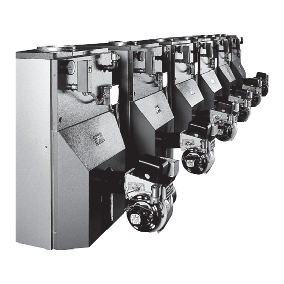
SFM CONSTELLATION SERIES
MODULAR OIL FIRED CAST IRON BOILERS
INSTALLATION, OPERATION &
MAINTENANCE MANUAL
Utica Boilers
2210 Dwyer Avenue, Utica NY 13504-4729
Phone: (315) 797-1310 • Fax: (866) 432-7329
e-mail: info@ecrinternational.com
27513401
P/N
, Rev. B [03/2011]
web site: www.ecrinternational.com
An ISO 9001-2008 Certified Company
Advertisement
Table of Contents

Related Manuals for UTICA BOILERS SFM CONSTELLATION Series


Summary of Contents for UTICA BOILERS SFM CONSTELLATION Series
- Page 1 SFM CONSTELLATION SERIES MODULAR OIL FIRED CAST IRON BOILERS INSTALLATION, OPERATION & MAINTENANCE MANUAL Utica Boilers 2210 Dwyer Avenue, Utica NY 13504-4729 Phone: (315) 797-1310 • Fax: (866) 432-7329 e-mail: info@ecrinternational.com 27513401 , Rev. B [03/2011] web site: www.ecrinternational.com An ISO 9001-2008 Certified Company...
-
Page 2: Table Of Contents
SFM SERIES MODULAR OIL FIRED CAST IRON BOILERS InstallatIon Manual and operatIng InstructIons TABLE OF CONTENTS CAUTION Safety Symbols ........2 Indicates a hazardous situation which, if not Dimensions ..........3 avoided, may result in minor or moderate Boiler Ratings & Capacities ....... 4 injury. -
Page 3: Dimensions
DIMENSIONS Model # code SERIES MODULAR DESIGN NO. OF PACKED BOILERS SECTIONS PER BOILER G.P.H. INPUT EACH FOR BOILER TYPE OF UNIT MultIple BoIler dIMensIonal data mODEL NO. SFM6225W * 29 ¼” 13 ⅝” 8” ——— SFM7275W * 32 ⅞” 13 ⅝”... -
Page 4: Boiler Ratings & Capacities
BOILER RATINGS, CAPACITIES & DIMENSIONS TOTAL FiRiNG BOiLER BOiLER pUmp iNpUT mODEL NO. NO. OF NOZZLE mODEL NO. RATE OUTpUT OUTpUT WATER WEiGHT pRESSURE m.B.H. OF mODULES mODULES FURNiSHED G.p.H. m.B.H. m.B.H. VOLUmE LBS. p.S.i 2.25 SFM6225W 19.5 2.00 45B SFH6225W 2.75 267.1... -
Page 5: Introduction
INTRODUCTION All installations must conform to the requirements FOR iNSTALLATiON ON NON-COmBUSTiBLE of the authority having jurisdiction. Such applicable FLOORS ONLY. The boiler must not be installed on requirements take precedence over the general carpeting or vinyl flooring. Minimum clearances to instructions of this manual. -
Page 6: Connecting Supply & Return Piping
CONNECTING SUPPLY AND RETURN PIPING Figure 1 - mODULAR BOiLER HOOK-Up RECOmmENDED pARALLEL pipiNG The recommended method of connecting the supply and return piping can be seen in Figure #1 below. (For detailed piping recommendations refer to the engineering manual) FRONT OF BOILER BRANCH MAIN... -
Page 7: Primary Secondary Piping
PRIMARY SECONDARY PIPING Figure 2 - pRimARY SECONDARY pipiNG An alternate method of connecting the supply and return piping can be seen in figure #2 below. (Refer to the engineering manual for detailed piping recommendations.) 12" PRIMARY LOOP AIR ELIMINATOR & EXPANSION TANK BRANCH... -
Page 8: Ventilation & Combustion Air
VENTILATION & COMBUSTION AIR WARNING Air openings to combustion area must not be obstructed. Follow the chart below to obtain and maintain adequate combustion air. COmBUSTiON AiR REQUiREmENTS (miNimUm OpENiNG iN SQUARE iNCHES) UNCONFiNED AREA CONFiNED AREA OUTSiDE iNSiDE OUTSiDE COmBUSTiON AiR COmBUSTiON AiR COmBUSTiON AiR... - Page 9 VENTILATION & COMBUSTION AIR 3. When air for combustion and room ventilation is 4. When the boiler is installed in a confined space from inside buildings, the confined space shall and all air is provided from the outdoors, the be provided with two permanent openings, one confined space shall be provided with two starting 12 inches from the top and one 12 inches permanent openings, one commencing within...
-
Page 10: Venting System Inspection & Installation
VENTILATION & COMBUSTION AIR Figure 4 - COmBUSTiON AiR SUppLiEDFROm iNSiDE THE BUiLDiNG APPROVED FITTINGS TYPICAL INSTALLATION SINGLE PIPE OIL SYSTEM WITH 2 OR MORE UNITS SWING JOINTS REFER TO NATIONAL BOARD OF FIRE UNDERWRITERS VENT PIPE FILLER PIPE OIL GAUGE MINIMUM SHUT OFF VALVE CLOSE... - Page 11 VENTING SYSTEM INSPECTION & INSTALLATION An unlined chimney will have leaks that will cause CHimNEY OR VENT SiZES poor chimney performance (NO DRAFT), and could DiA. OF CHimNEY result in poor positive pressure in the combustion FLUE CHimNEY SiZE mODEL NO. OUTLET chamber.
-
Page 12: Oil Tank Installation & Piping
OIL TANK AND PIPING Oil tank and piping should be installed in accordance Fuel pump connections and by-pass should be with the National Board of Fire Underwriters and local made according to instructions attached to the regulations. Oil storage tank, vent, fill pipe and caps fuel pump. -
Page 13: Thermostat Installation
OIL TANK AND PIPING Figure 8 - COmBUSTiON AiR SUppLiED FROm iNSiDE THE BUiLDiNG TYPICAL INSTALLATION BURRIED TANK OIL SYSTEM WITH 2 OR MORE UNITS APPROVED FITTINGS APPROVED DAY TANK OR AUX. TANK WITH BOOST PUMP MANIFOLD .5" FILL PIPE SWING JOINTS SUCTION... -
Page 14: Operating Instructions
OPERATING INSTRUCTIONS The venting system should be inspected at the start CAUTION of each heating season. Check the vent pipe from the boiler to the chimney for signs of deterioration by Do not set fire visually. rust or sagging joints. Repair if necessary. Instruments are the only reliable method to Remove the vent pipe at the base of the chimney or determine proper air adjustments. - Page 15 OPERATING INSTRUCTIONS model Static Air Band Air Shutter Head Low Firing Cone Disc Setting Setting Setting Rate Baffle SFM4150 2¾ ––––– SFM5175 F-12 ––––– SFM5200 F-12 ––––– SFM6225 ––––– ––––– SFM7275 ––––– ––––– Information in above table uses Beckett model AFG burner for model numbers SFM4150-5200 and Beckett model SMG for models 6225 and 7275.
- Page 16 OPERATING INSTRUCTIONS Using a flue brush, brush the soot and scale into the CAUTION combustion space where it can be removed through the swing door opening. Use caution when vacuuming in the chamber area. Damage to chamber could result. It is recommended to replace the nozzle at the start of each heating season.
-
Page 17: Control System
CONTROL SYSTEMS ELECTRiCAL WiRiNG should conform with the latest edition of National Electrical Code ANSI/NFPA No. 70 and/or local authority having jurisdiction. A separate electrical circuit should be run from the entry box with a fused disconnect switch in this circuit. Refer to component coding and wiring code for the following control systems and wiring diagrams. - Page 18 CONTROL SYSTEMS Figure 11 - ARGO AmB4 mODULE WiRiNG...
-
Page 19: Service Check List
SERVICE CHECK LIST AND RECORD CHART Inspect Chimney and Flue pipe Pump Pressure/Vacuum Inspect and Clean Appliance Line Voltage/Motor Amps Inspect Oil Line - Size/Leaks Smoke Test Inspect Electrical Connections Draft-Overfire/In Flue Install New Fliter or O Room Make-up Air Flue Gas Temperature Electrode setting Proper Light-Off (Hot &... -
Page 20: Heat Exchanger
SFM SERIES REPLACEMENT PARTS Figure 12 - HEAT EXCHANGER FULLY ASSEmBLED HEAT EXCHANGERS 10023402 4 SECTION 10023403 5 SECTION 10023404 6 SECTION 10023405 7 SECTION iTEm pART # DESCRipTiON iTEm pART # DESCRipTiON 10051702 REAR SECTION #60 PUSH NIPPLE HW-025.01 TIE ROD ½... - Page 21 SFM SERIES REPLACEMENT PARTS Figure 13 - SWiNG DOOR AND mOUNTiNG DOOR COmpONENTS iTEm pART # DESCRipTiON 2552901 MOUNTING DOOR INSULATION & PLUG HW-005.01 SCREW ¼ -20 X ½ SELF TAPPING 10011701 OBSERVATION DOOR 25511101 OBS. DOOR GASKET HW06801 ¼ X 1¾ DRIVE LOCK PIN 10011501 SWING DOOR HW06701...
-
Page 22: Swing Door & Mounting Door Components .21 Jacket
SFM SERIES REPLACEMENT PARTS Figure 14 - JACKET ITEM PART # DESCRIPTION 21521803 SIDE PANEL 4 SECTION 21521804 SIDE PANEL 5 SECTION 21521805 SIDE PANEL 6 SECTION 21521806 SIDE PANEL 7 SECTION 21522401 TOP FRONT PANEL C/O 21521901 LOWER COWL 21521501 REAR PANEL 215-1-... -
Page 23: Hardware
SFM SERIES REPLACEMENT PARTS Figure 15 - HARDWARE iTEm pART # DESCRipTiON HW-005.01 SCREW ¼ -20 X ½ SELF TAP 2452902 FLUE COLLECTOR ASSY (4 SECT) 2452903 FLUE COLLECTOR ASSY (5 SECT) 2452907 FLUE COLLECTOR ASSY (6 SECT) 2452908 FLUE COLLECTOR ASSY (7 SECT) HW06701 STUD ⁄... -
Page 24: Controls & Hardware
SFM SERIES REPLACEMENT PARTS Figure 16 - CONTROLS & HARDWARE TOP FRONT PANEL (SEE PREVIOUSE PAGE) TO BURNER iTEm # pART # DESCRipTiON AQ-020.01 WELL ¾” X 3” AQ-008.00 CONTROL L4006A-1827 HW LIMIT GA-001.00 GAUGE - THERALTIMETER VR-001.01 RELIEF VALVE - 30# ¾” PF-002.04 PIPE FITTING - 90°... - Page 26 NOTES...
- Page 28 UTiCA BOiLERS 2210 Dwyer Avenue, Utica NY 13504-4729 Phone: (315) 797-1310 • Fax: (866) 432-7329 e-mail: info@ecrinternational.com web site: www.ecrinternational.com...
Need help?
Do you have a question about the SFM CONSTELLATION Series and is the answer not in the manual?
Questions and answers