UTICA BOILERS SFH-3085 Installation, Operation & Maintenance Manual
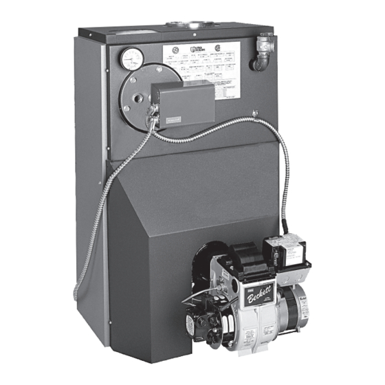
Starfire iv series 4 water oil fired cast iron boiler
Hide thumbs
Also See for SFH-3085:
- Installation, operation & maintenance manual (24 pages) ,
- Installation, operation & maintenance manual (28 pages)
Advertisement
Table of Contents
Models
SFH-3085
SFH-3100
SFH-4100
SFH-4125
SFH-4145
SFH-5160
SFH-5185
SFH-6175
SFH-6210
An ISO 9001-2008 Certified Company
STARFIRE IV SERIES 4
CAST IRON BOILER
INSTALLATION, OPERATION &
MAINTENANCE MANUAL
Tested For 75 psi
ASME
Working Pressure
WATER
OIL FIRED
ECR International, Inc.
2201 Dwyer Avenue, Utica NY 13501
web site: www.ecrinternational.com
240009735
P/N
Manufactured by:
, Rev. F [12/2014]
Advertisement
Table of Contents

Subscribe to Our Youtube Channel
Related Manuals for UTICA BOILERS SFH-3085


Summary of Contents for UTICA BOILERS SFH-3085
- Page 1 STARFIRE IV SERIES 4 WATER OIL FIRED CAST IRON BOILER Models SFH-3085 INSTALLATION, OPERATION & SFH-3100 MAINTENANCE MANUAL SFH-4100 SFH-4125 SFH-4145 SFH-5160 SFH-5185 SFH-6175 SFH-6210 Tested For 75 psi ASME Manufactured by: Working Pressure ECR International, Inc. 2201 Dwyer Avenue, Utica NY 13501 web site: www.ecrinternational.com...
-
Page 2: Table Of Contents
TABLE OF CONTENTS Dimensions ........................3 Boiler Ratings & Capacities.................... 4 Introduction ........................5 Ventilation & Combustion Air ..................6 Connecting Supply And Return Piping ................9 System Piping ......................13 Venting System Inspection & Installation..............16 Oil Tank And Piping ..................... 17 Electrical Wiring ...................... -
Page 3: Dimensions
DIMENSIONS DIMENSIONAL DATA FRONT OF DEPTH DIA. BOILER CASING SECTION TO CENTER LINE FLUSH FLUE JACKET OUTLET FLUE OUTLET 17 ⅞" 11 ¼" 6" 21 ½" 12 ⅝" 6" 25 ⅛" 14 ¼" 7" 29¼ 15 ¹⁵/ ” 8”... -
Page 4: Boiler Ratings & Capacities
BOILER RATINGS & CAPACITIES BOILER RATINGS OIL BURNER HEATING CHIMNEY BOILER RATINGS A.F.U.E. INPUT CAPACITY MODEL WATER NUMBER *Mbh *Mbh *Mbh SFH-3085W SFH-3085WT 0.85 85.0% 8X8X15 SFH-3100W SFH-3100WT 1.00 84.0% 8X8X15 SFH-4100W SFH-4100WT 1.00 86.0% 8X8X15 SFH-4125W SFH-4125WT 1.25 85.0% 8X8X15 SFH-4145W SFH-4145WT... -
Page 5: Introduction
INTRODUCTION • Allow 24 inches in the front and top for servicing and WARNING cleaning, or removing tankless water heating coil. Improper installation, adjustment, alteration, service • When installed in utility room, door should be wide or maintenance could result in death or serious enough to allow largest boiler part to enter, or to permit injury. -
Page 6: Ventilation & Combustion Air
VENTILATION & COMBUSTION AIR WARNING Asphyxiation, fire hazard. Do not obstruct air openings to combustion area. Follow instructions below, to maintain adequate combustion air. COMBUSTION AIR REQUIREMENTS (MINIMUM OPENING IN SQUARE INCHES) *UNCONFINED AREA **CONFINED AREA OUTSIDE INSIDE OUTSIDE COMBUSTION AIR COMBUSTION AIR COMBUSTION AIR INPUT... - Page 7 VENTILATION & COMBUSTION AIR When air for combustion and room ventilation is from B. When communicating with the outdoors by means inside buildings, confined space shall be provided with of vertical ducts, each opening shall have a two permanent openings, one starting 12 inches from minimum free area 1 square inch per 4,000 Btu per the top and one 12 inches from the bottom of the hour of total input rating of all appliances in the...
- Page 8 VENTILATION & COMBUSTION AIR Figure #2 Figure #3 Figure #4...
-
Page 9: Connecting Supply And Return Piping
CONNECTING SUPPLY AND RETURN PIPING Connect supply and return piping as suggested in Hot water boilers installed above radiation level must Figure #5, below. When boiler is used in connection be provided with low water device either as part of with refrigerated systems: boiler or at time of boiler installation. - Page 10 CONNECTING SUPPLY AND RETURN PIPING A. This method is used to protect boilers from C. This method is used to protect boilers from condensate forming due to low temperature return condensate forming as well as protecting heating water. Generally noticed in large converted gravity system from high water temperature.
- Page 11 CONNECTING SUPPLY AND RETURN PIPING Figure #7 - Mixing Valve Piping Figure #8 - Primary Secondary Piping With Bypass...
- Page 12 CONNECTING SUPPLY AND RETURN PIPING Typical indirect water heater installation using circulators is shown in Figure #9. Typical indirect water heater installation using zone valves is shown in Figure #10. Figure #9 - Indirect Water Heater Piping with Circulator DRAIN VALVE Figure #10 - Indirect Water Heater Piping with Zone Valve DRAIN VALVE...
-
Page 13: System Piping
SYSTEM PIPING WARNING Burn or Scald Hazard. Discharge line shall be installed to relief valve outlet connection to avoid burns, scalding, or water damage due to discharge of steam and/or hot water during operation. Discharge line shall: • Connect to safety valve outlet. Piped down to safe point of disposal. Check local codes for maximum distance from floor or allowable safe point of discharge. - Page 14 CONNECTING SUPPLY AND RETURN PIPING Figure #12 - Recommended Piping For Boilers Equipped With T3 Or T4 Tankless Heater DANGER Water temperatures exceeding 125°F will cause severe burns instantly or death by scalding. • Automatic mixing valve must be installed on outlet of domestic coil.
- Page 15 CONNECTING SUPPLY AND RETURN PIPING OPTIONS UTILIZING 3/4” TAPPING Figure #13 - Optional Location For Air Vent Figure #14 - Optional Location For Expansion Tank (Non-Diaphragm Type)
-
Page 16: Venting System Inspection & Installation
VENTING SYSTEM INSPECTION & INSTALLATION INSPECT CHIMNEY to verify it is constructed according Figure #15 to latest revision of the NFPA 211. Local codes may differ from this code and should be checked. Where there is a conflict, local code will prevail. •... -
Page 17: Oil Tank And Piping
OIL TANK AND PIPING • Install burner per instructions provided with burner-in- • Do not run overhead fuel lines from tank to oil burner. a-box kit. • Fuel pump connections and by-pass should be made • Install oil tank and piping in accordance with the according to instructions attached to fuel pump. -
Page 18: Electrical Wiring
ELECTRICAL WIRING Sequence Of Operations WARNING On call for heat, thermostat will actuate, completing Electrical shock hazard. Turn OFF electrical power supply circuit to limit. In turn, circulator and ignition systems are at service panel before making electrical connections. activated and ignition will begin. Failure to do so could result in death or serious injury. - Page 19 ELECTRICAL WIRING Figure #18 - Wiring Diagram Beckett AFG without Tankless Heater Figure #19 Wiring Diagram Beckett AFG wth Tankless Heater...
- Page 20 ELECTRICAL WIRING Figure #20 Wiring Diagram Riello 40F5 without Tankless Heater Figure #21 Wiring Diagram Riello 40F5 with Tankless Heater...
- Page 21 ELECTRICAL WIRING Figure #22 Wiring Diagram Riello 40F10 without Tankless Heater Figure #23 Wiring Diagram Riello 40F10 with Tankless Heater...
- Page 22 ELECTRICAL WIRING Figure #24 Wiring Diagram Carlin EZ-1/2 without Tankless Heater Figure #25 Wiring Diagram Carlin EZ-1/2 with Tankless Heater...
-
Page 23: Operating Instructions
OPERATING INSTRUCTIONS Operating Instructions Do not set fire visually. Instruments are only reliable method to determine proper air adjustments. Inspect venting system at start of each heating season. Improperly adjusted burner causes soot and high fuel bills Check vent pipe from boiler to chimney for signs because of incomplete combustion of fuel oil. - Page 24 OPERATING INSTRUCTIONS Preventive Maintenance - of oil fired boiler reduces Close oil valve. See Figures #16 & #17. operating costs. Boiler and vent pipe should be inspected Disconnect oil line from burner. for accumulation of soot or scale deposits periodically Do not try to swing door with oil line attached.
- Page 25 OPERATING INSTRUCTIONS TABLE 1 - BECKETT AFG SETTINGS PUMP BOILER HEAD HEAD STATIC NOZZLE PRESSURE MODEL TYPE SETTING PLATE BAND SHUTTER [PSI] SFH-3085W(T) 3⅜ 0.75-60°B SFH-3100W(T) 3⅜ 0.85-60°B SFH-4100W(T) 2¾ 0.85-60°B SFH-4125W(T) 2¾ 1.10-60°B SFH-4145W(T) 2¾ 1.25-60°B SFH-5160W(T) 2¾ 1.35-70°B SFH-5185W(T) 2¾...
- Page 26 OPERATING INSTRUCTIONS Figure #26 SAFETY RELIEF VALVE Instructions For Closing Burner Swing Door Swing burner and door to right until insulation is slightly compressed and stud is exposed. Attach nut to stud and tighten until built in stop contacts the mounting door. Replace oil line to burner.
- Page 27 SERVICE RECORD...
- Page 28 • This boiler is part of a modular or multiple boiler system having a total input of 300,000 BTU/hr or greater. • This boiler is equipped with a tankless coil. UTICA BOILERS 2201 Dwyer Avenue Utica NY 13501 web site: www.ecrinternational.com...
Need help?
Do you have a question about the SFH-3085 and is the answer not in the manual?
Questions and answers